

90 Part I: AutoCAD 101
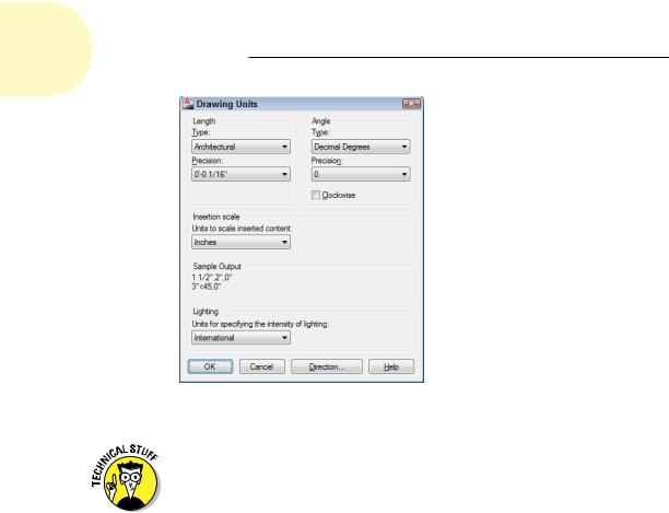
Figure 4-1: The Drawing Units dialog box.
When you use dash-dot linetypes (Chapter 6) and hatching (Chapter 15) in a drawing, it matters to AutoCAD whether the drawing uses an imperial (inches, feet, miles, and so on) or metric (millimeters, meters, kilometers,
and so on) system of measure. The MEASUREMENT system variable controls whether the linetype and hatch patterns that AutoCAD lists for you to choose from are scaled with inches or millimeters in mind as the plotting units.
MEASUREMENT=0 means inches (that is, an imperial-units drawing), whereas MEASUREMENT=1 means millimeters (that is, a metric-units drawing). If you start from an appropriate template drawing (as described in the section “A Template for Success,” later in this chapter), the MEASUREMENT system variable will be set correctly, and you won’t ever have to think about it. (For an explanation of system variables and how to set them, see Chapter 26.)
Weighing up your scales
The next decision you should make before setting up a new drawing is choosing the scale at which you’ll eventually plot the drawing. This decision gives you the drawing scale and drawing scale factor — two ways of expressing the same relationship between the objects in the real world and the objects plotted on paper.
“Okay,” you’re saying, “I understand that I need to print my drawings at a scale acceptable to the discipline I work in. But if I’m drawing stuff full size, why do I need to worry about the scale factor?” Grab yourself a nice mug of cocoa and settle down ’round the fire, because I’m going to tell you. By now you know (because I’ve told you so) that you draw real things full size, but
www.it-ebooks.info
Chapter 4: Setup for Success |
91 |
drawings contain other things that are not real, such as text, dimensions, hatch patterns, title blocks, dash-dot linetypes, and so forth. And those nonreal things need to be legible on your plotted drawing.
Say, for example, you want to draw a plan of your garage. You need it to fit on an 11-x-17-inch sheet of paper, and you want to add a title like (if you’re really original like me) “My Garage.” Typically, text annotations are 3⁄32" or 1⁄8" high.
Now, if you draw your 6"-wide wall full size, put a 1⁄8"-high title beside it, and then print the drawing at a scale of, say, 1:24 (that’s 1 drawing inch equals 24 real inches, usually expressed as 1⁄2" = 1'-0"), the 6" wall itself will measure 1⁄4" on the sheet, and the note will be an illegible little speck beside it. You fix it with the help of the drawing scale factor; the “Drawing scale versus drawing scale factor” sidebar explains how you arrive at the scale factor, and Table 4-1, in the following section, presents a list of acceptable standard scales with their corresponding scale factors for both imperial and metric systems of measure.
Thinking annotatively
A few years back, AutoCAD introduced a new way of setting some types of annotation objects to the appropriate plotted size. Annotative objects possess a special property so that when you change the annotation scale of a layout’s viewport or of the model tab, all the annotative objects — including text, dimensions, dash-dot linetypes, hatch patterns, and symbol blocks — change automatically to their correct size for the chosen scale. We take a closer look at annotative objects in Chapter 13, but in the meantime, it’s still worthwhile getting familiar with using drawing scale factors because they’re useful in a few other ways and because millions of drawings exist that were created this way.
Drawing scale versus drawing scale factor
CAD users employ two different ways of talking about a drawing’s intended plot scale: drawing scale and drawing scale factor.
Drawing scale is the traditional way of describing a scale — traditional because it existed long before CAD came to be. Drawing scales are expressed with an equal sign or colon — for example, 1⁄8" = 1'–0", 1:20, or 2:1. You can translate the equal sign or colon as “corresponds to.” In all cases, the measurement to the left of the equal sign or colon indicates a paper measurement, and the number to the right indicates a real-world measurement. In other words, the imperial drawing scale 1⁄8" = 1'–0" means that
1⁄8" on the plotted drawing corresponds to 1'–0" in the CAD drawing in the real world, assuming that the plot was made at the proper scale. A metric drawing scale is usually expressed without units, as a simple ratio. Thus, a scale of 1:20 means 1 unit on the plotted drawing corresponds to 20 units in the real world. In architectural and engineering drawings, the numbers usually refer to millimeters.
Drawing scale factor is a single number that represents a multiplier, such as 96, 20, or 0.5. The drawing scale factor for a drawing is the conversion factor between a measurement on the plot and a measurement in the real world.
www.it-ebooks.info
92 Part I: AutoCAD 101
You shouldn’t just invent some arbitrary scale based on what looks okay on whatever size paper you happen to have handy. Most industries work with a small set of approved drawing scales that are related to one another by factors of 2 or 10. If you use other scales, at best you’ll be branded a clueless newbie — and at worst you’ll have to redo all your drawings at an accepted scale.
Table 4-1 lists some common architectural drawing scales, using both imperial and metric systems of measure. The table also lists the drawing scale factor corresponding to each drawing scale and the common uses for each scale. If you work in industries other than those listed here, ask drafters or co-workers what the common drawing scales are and for what kinds of drawings they’re used.
Table 4-1 |
Common Architectural Drawing Scales |
|
Drawing Scale |
Drawing Scale Factor |
Common Uses |
1⁄16" = 1'–0" |
192 |
Large-building plans |
1⁄8" = 1'–0" |
96 |
Medium-sized building plans |
1⁄4" = 1'–0" |
48 |
House plans |
1⁄2" = 1'–0" |
24 |
Small-building plans |
1" = 1'–0" |
12 |
Details |
|
|
|
1:200 |
200 |
Large building plans |
1:100 |
100 |
Medium-sized building plans |
|
|
|
1:50 |
50 |
House plans |
|
|
|
1:20 |
20 |
Small building plans |
|
|
|
1:10 |
10 |
Details |
After you choose a drawing scale, engrave the corresponding drawing scale factor on your desk, write it on your hand (don’t mix those two up, okay?), and put it on a sticky note on your monitor. You need to know the drawing scale factor for many drawing tasks, as well as for some plotting. You should be able to recite the drawing scale factor of any drawing you’re working on in AutoCAD without even thinking about it.
Even if you’re going to use the Plot dialog box’s Fit to Paper option (rather than a specific scale factor) to plot the drawing, you still need to choose a scale to make the nonreal things (such as text, dash-dot linetypes, hatch patterns, and so on) appear at a useful size. Choose a scale that’s in the neighborhood of the Fit to Paper plotting factor, which AutoCAD displays in the Plot Scale area of the Plot dialog box. For example, if you determine that you need to squeeze your drawing down about 90 times to fit on the desired sheet size, choose a drawing scale of 1⁄8" = 1'–0" (drawing scale factor = 96) if
www.it-ebooks.info
Chapter 4: Setup for Success |
93 |
you’re using architectural units or 1:100 (drawing scale factor = 100) for other kinds of units.
Thinking about paper
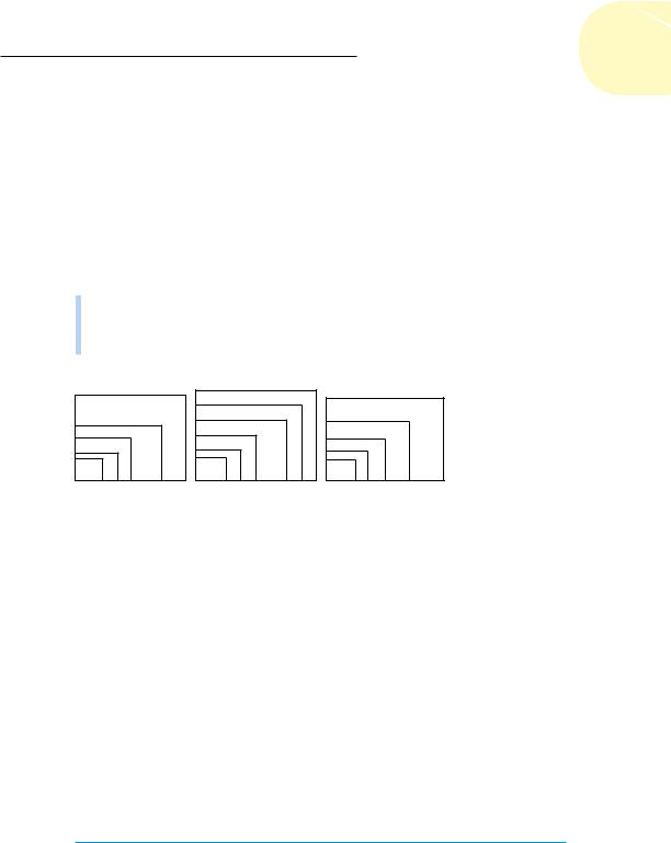
With knowledge of your industry’s common drawing scales, you can choose a provisional scale based on what you’re depicting. But you won’t know for sure whether that scale works until you compare it with the size of the paper that you want to use for plotting your drawing. Here again, most industries use a small range of standard sheet sizes. Three common sets of sizes exist, as shown in Figure 4-2 and Table 4-2:
ANSI (American National Standards Institute)
Architectural
ISO (International Organization for Standardization)
|
|
E |
|
LARGE E |
|
A0 |
|
|
|
E |
|
||
|
|
|
|
|
|
|
|
D |
|
|
D |
|
A1 |
|
|
|
C |
|
|
|
|
C |
|
|
|
A2 |
|
A |
B |
|
A |
B |
A4 |
A3 |
|
|
|
|
|||
|
ANSI sizes |
|
Architectural sizes |
|
ISO sizes |
|
Figure 4-2: Relationships among standard paper sizes.
Table 4-2 |
Common Plot Sheet Sizes |
|
Sheet Size |
Dimensions |
Comment |
|
|
|
ANSI E |
34 x 44" |
|
|
|
|
ANSI D |
22 x 34" |
E sheet folded in half |
|
|
|
ANSI C |
17 x 22" |
D sheet folded in half |
ANSI B |
11 x 17" |
C sheet folded in half |
ANSI A |
81⁄2 x 11" |
B sheet folded in half = letter size |
Architectural Large E |
36 x 48" |
|
|
|
|
Architectural E |
30 x 42" |
|
|
|
|
Architectural D |
24 x 36" |
Large E sheet folded in half |
|
|
|
Architectural C |
18 x 24" |
D sheet folded in half |
Architectural B |
12 x 18" |
C sheet folded in half |
(continued)
www.it-ebooks.info

94 Part I: AutoCAD 101
Table 4-2 (continued)
Sheet Size |
Dimensions |
Comment |
|
|
|
Architectural A |
9 x 12" |
B sheet folded in half |
|
|
|
ISO A0 |
841 x 1189 mm |
|
ISO A1 |
594 x 841 mm |
A0 sheet folded in half |
ISO A2 |
420 x 594 mm |
A1 sheet folded in half |
|
|
|
ISO A3 |
297 x 420 mm |
A2 sheet folded in half |
|
|
|
ISO A4 |
210 x 297 mm |
A3 sheet folded in half |
You select a particular set of sheet sizes based on the common practices in your industry. You then narrow down your choice based on the area required by what you’re going to draw. For example, most imperial-units architectural plans are plotted on Architectural or ANSI D- or E-size sheets, and most metric architectural plans go on ISO A1 or A0 sheets.
If you know the desired sheet size and drawing scale factor, you can calculate the available drawing area easily. Simply multiply each of the sheet’s dimensions by the drawing scale factor. For example, if you choose an 11-x-17-
inch sheet and a drawing scale factor of 96 (corresponding to a plot scale of 1⁄8" = 1'–0"), you multiply 17 times 96, and 11 times 96, to get an available drawing area of 1,632 x 1,056 inches (or 136 x 88 feet). If your sheet size is in inches but your drawing scale is in millimeters, you need to multiply by an additional 25.4 to convert from inches to millimeters. For example, with an 11-x-17-inch sheet and a scale of 1:200 (drawing scale factor = 200), you multiply 17 times 200 times 25.4, and 11 times 200 times 25.4, to get 86,360 x 55,880mm or 86.36 x 55.88mm — not quite big enough for a football field (American or European football).
Conversely, if you know the sheet size that you’re going to use and the realworld size of what you’re going to draw, and you want to find out the largest plot scale you can use, you have to divide, not multiply. Divide the needed real-world drawing area’s length and width by the sheet’s dimensions. Take the larger number — either the length result or the width result — and round up to the nearest real drawing scale factor (that is, one that’s commonly used in your industry). For example, suppose you want to draw a 60-x-40-foot (or 720-x-480-inch) floor plan and print it on 11-x-17-inch paper. You divide 720 by 17, and 480 by 11, to get 42.35 and 43.64, respectively. The larger number, 43.64, corresponds in this example to the short dimension of the house and the paper. The nearest larger common architectural drawing scale factor is 48 (corresponding to 1⁄4" = 1'–0"), which leaves a little room for the plotting margin and title block.
www.it-ebooks.info
Chapter 4: Setup for Success |
95 |
The Cheat Sheet at this book’s companion website (www.dummies.com/ cheatsheet/autocad2013) includes two tables that list the available drawing areas for a range of sheet sizes and drawing scales. Those tables can help you decide on an appropriate paper size and drawing scale; revert to the calculation method for situations that the tables don’t cover. If you don’t keep a favorite old calculator on your physical desktop, don’t despair: AutoCAD 2013 has one lurking on the Ribbon. You’ll find it on the Home tab’s Utilities panel. (Hint: It looks like a calculator.) You speed demons can toggle QuickCalc off and on with the Ctrl+8 key combo!
When you select a sheet size and drawing scale, always leave some extra room, for the following three reasons:
Margin allowance: Most plotters and printers can’t print all the way to the edge of the sheet — they require a small margin. For example, my trusty old Hewlett-Packard LaserJet 4050 has a printable area of about 8.0 x 10.7 inches on an 8.5-x-11-inch ANSI A-size (letter-size) sheet. (You can find this information in the Plot dialog box, as described in Chapter 16.) If you’re a stickler for precision, you can use the printable area instead of the physical sheet area in the calculations described earlier in this section.
Annotations: Most drawings require some annotations — text, dimensions, grid bubbles, and so on — outside the objects you’re drawing, plus a title block surrounding the objects and annotations. If you don’t leave some room for the annotations and title block, you’ll end up having to cram things together too much or change to a different sheet size. Either way, you’ll be slowed down later in the project, when you can least afford it.
Multiple views: Many objects require multiple orthographic views, and details at other scales.
Some industries deal with the sheet-is-too-small/drawing-scale-is-too-large problem by breaking up drawings onto multiple plotted sheets. You might consider doing the same.
Don’t be afraid to start with real paper. Experienced drafters often make a quick, throwaway pencil-and-paper sketch indicating the dimensions of the sheet of paper they intend to plot on, a sketch of the title block, and a very rough, schematic sketch of the thing they’re going to draw. By sketching on paper first, you’ll often catch scale or sheet-size problems before you set up a drawing, when repairs take only a few minutes — not after you’ve created the drawing, when fixing the problem can take hours.
www.it-ebooks.info