

- •About the Authors
- •Dedication
- •Authors’ Acknowledgments
- •Table of Contents
- •Introduction
- •What’s Not (And What Is) in This Book
- •Mac attack!
- •Who Do We Think You Are?
- •How This Book Is Organized
- •Part I: AutoCAD 101
- •Part II: Let There Be Lines
- •Part III: If Drawings Could Talk
- •Part IV: Advancing with AutoCAD
- •Part V: On a 3D Spree
- •Part VI: The Part of Tens
- •But wait . . . there’s more!
- •Icons Used in This Book
- •A Few Conventions — Just in Case
- •Commanding from the keyboard
- •Tying things up with the Ribbon
- •Where to Go from Here
- •Why AutoCAD?
- •The Importance of Being DWG
- •Seeing the LT
- •Checking System Requirements
- •Suddenly, It’s 2013!
- •AutoCAD Does Windows (And Office)
- •And They’re Off: AutoCAD’s Opening Screens
- •Running with Ribbons
- •Getting with the Program
- •Looking for Mr. Status Bar
- •Let your fingers do the talking: The command window
- •The key(board) to AutoCAD success
- •Keeping tabs on palettes
- •Down the main stretch: The drawing area
- •Fun with F1
- •A Simple Setup
- •Drawing a (Base) Plate
- •Drawing rectangles on the right layers
- •Circling your plate
- •Nuts to you
- •Getting a Closer Look with Zoom and Pan
- •Modifying to Make It Merrier
- •Hip-hip-array!
- •Stretching out
- •Crossing your hatches
- •Following the Plot
- •A Setup Roadmap
- •Choosing your units
- •Weighing up your scales
- •Thinking annotatively
- •Thinking about paper
- •Defending your border
- •A Template for Success
- •Making the Most of Model Space
- •Setting your units
- •Making the drawing area snap-py (and grid-dy)
- •Setting linetype and dimension scales
- •Entering drawing properties
- •Making Templates Your Own
- •Setting Up a Layout in Paper Space
- •Will that be tabs or buttons?
- •View layouts Quick(View)ly
- •Creating a layout
- •Copying and changing layouts
- •Lost in paper space
- •Spaced out
- •A view(port) for drawing in
- •About Paper Space Layouts and Plotting
- •Managing Your Properties
- •Layer one on me!
- •Accumulating properties
- •Creating new layers
- •Manipulating layers
- •Using Named Objects
- •Using AutoCAD DesignCenter
- •Copying layers between drawings
- •Controlling Your Precision
- •Keyboard capers: Coordinate input
- •Understanding AutoCAD’s coordinate systems
- •Grab an object and make it snappy
- •Other Practical Precision Procedures
- •Introducing the AutoCAD Drawing Commands
- •The Straight and Narrow: Lines, Polylines, and Polygons
- •Toeing the line
- •Connecting the lines with polyline
- •Squaring off with rectangles
- •Choosing your sides with polygon
- •(Throwing) Curves
- •Going full circle
- •Arc-y-ology
- •Solar ellipses
- •Splines: The sketchy, sinuous curves
- •Donuts: The circles with a difference
- •Revision clouds on the horizon
- •Scoring Points
- •Commanding and Selecting
- •Command-first editing
- •Selection-first editing
- •Direct object manipulation
- •Choosing an editing style
- •Grab It
- •One-by-one selection
- •Selection boxes left and right
- •Perfecting Selecting
- •AutoCAD Groupies
- •Object Selection: Now You See It . . .
- •Get a Grip
- •About grips
- •A gripping example
- •Move it!
- •Copy, or a kinder, gentler Move
- •A warm-up stretch
- •Your AutoCAD Toolkit
- •The Big Three: Move, Copy, and Stretch
- •Base points and displacements
- •Move
- •Copy
- •Copy between drawings
- •Stretch
- •More Manipulations
- •Mirror
- •Rotate
- •Scale
- •Array
- •Offset
- •Slicing, Dicing, and Splicing
- •Trim and Extend
- •Break
- •Fillet and Chamfer and Blend
- •Join
- •When Editing Goes Bad
- •Zoom and Pan with Glass and Hand
- •The wheel deal
- •Navigating your drawing
- •Controlling your cube
- •Time to zoom
- •A View by Any Other Name . . .
- •Looking Around in Layout Land
- •Degenerating and Regenerating
- •Getting Ready to Write
- •Simply stylish text
- •Taking your text to new heights
- •One line or two?
- •Your text will be justified
- •Using the Same Old Line
- •Turning On Your Annotative Objects
- •Saying More in Multiline Text
- •Making it with Mtext
- •It slices; it dices . . .
- •Doing a number on your Mtext lists
- •Line up in columns — now!
- •Modifying Mtext
- •Gather Round the Tables
- •Tables have style, too
- •Creating and editing tables
- •Take Me to Your Leader
- •Electing a leader
- •Multi options for multileaders
- •How Do You Measure Up?
- •A Field Guide to Dimensions
- •The lazy drafter jumps over to the quick dimension commands
- •Dimension associativity
- •Where, oh where, do my dimensions go?
- •The Latest Styles in Dimensioning
- •Creating and managing dimension styles
- •Let’s get stylish!
- •Adjusting style settings
- •Size Matters
- •Details at other scales
- •Editing Dimensions
- •Editing dimension geometry
- •Editing dimension text
- •Controlling and editing dimension associativity
- •Batten Down the Hatches!
- •Don’t Count Your Hatches. . .
- •Size Matters!
- •We can do this the hard way. . .
- •. . . or we can do this the easy way
- •Annotative versus non-annotative
- •Pushing the Boundary (Of) Hatch
- •Your hatching has no style!
- •Hatch from scratch
- •Editing Hatch Objects
- •You Say Printing, We Say Plotting
- •The Plot Quickens
- •Plotting success in 16 steps
- •Get with the system
- •Configure it out
- •Preview one, two
- •Instead of fit, scale it
- •Plotting the Layout of the Land
- •Plotting Lineweights and Colors
- •Plotting with style
- •Plotting through thick and thin
- •Plotting in color
- •It’s a (Page) Setup!
- •Continuing the Plot Dialog
- •The Plot Sickens
- •Rocking with Blocks
- •Creating Block Definitions
- •Inserting Blocks
- •Attributes: Fill-in-the-Blank Blocks
- •Creating attribute definitions
- •Defining blocks that contain attribute definitions
- •Inserting blocks that contain attribute definitions
- •Edit attribute values
- •Extracting data
- •Exploding Blocks
- •Purging Unused Block Definitions
- •Arraying Associatively
- •Comparing the old and new ARRAY commands
- •Hip, hip, array!
- •Associatively editing
- •Going External
- •Becoming attached to your xrefs
- •Layer-palooza
- •Creating and editing an external reference file
- •Forging an xref path
- •Managing xrefs
- •Blocks, Xrefs, and Drawing Organization
- •Mastering the Raster
- •Attaching a raster image
- •Maintaining your image
- •Theme and Variations: Dynamic Blocks
- •Lights! Parameters!! Actions!!!
- •Manipulating dynamic blocks
- •Maintaining Design Intent
- •Defining terms
- •Forget about drawing with precision!
- •Constrain yourself
- •Understanding Geometric Constraints
- •Applying a little more constraint
- •AutoConstrain yourself!
- •Understanding Dimensional Constraints
- •Practice a little constraint
- •Making your drawing even smarter
- •Using the Parameters Manager
- •Dimensions or constraints — have it both ways!
- •The Internet and AutoCAD: An Overview
- •You send me
- •Send it with eTransmit
- •Rapid eTransmit
- •Bad reception?
- •Help from the Reference Manager
- •Design Web Format — Not Just for the Web
- •All about DWF and DWFx
- •Autodesk Design Review 2013
- •The Drawing Protection Racket
- •Autodesk Weather Forecast: Increasing Cloud
- •Working Solidly in the Cloud
- •Free AutoCAD!
- •Going once, going twice, going 123D
- •Your head planted firmly in the cloud
- •The pros
- •The cons
- •Cloudy with a shower of DWGs
- •AutoCAD 2013 cloud connectivity
- •Tomorrow’s Forecast
- •Understanding 3D Digital Models
- •Tools of the Trade
- •Warp speed ahead
- •Entering the third dimension
- •Untying the Ribbon and opening some palettes
- •Modeling from Above
- •Using 3D coordinate input
- •Using point filters
- •Object snaps and object snap tracking
- •Changing Planes
- •Displaying the UCS icon
- •Adjusting the UCS
- •Navigating the 3D Waters
- •Orbit à go-go
- •Taking a spin around the cube
- •Grabbing the SteeringWheels
- •Visualizing 3D Objects
- •Getting Your 3D Bearings
- •Creating a better 3D template
- •Seeing the world from new viewpoints
- •From Drawing to Modeling in 3D
- •Drawing basic 3D objects
- •Gaining a solid foundation
- •Drawing solid primitives
- •Adding the Third Dimension to 2D Objects
- •Creating 3D objects from 2D drawings
- •Modifying 3D Objects
- •Selecting subobjects
- •Working with gizmos
- •More 3D variants of 2D commands
- •Editing solids
- •Get the 2D Out of Here!
- •A different point of view
- •But wait! There’s more!
- •But wait! There’s less!
- •Do You See What I See?
- •Visualizing the Digital World
- •Adding Lighting
- •Default lighting
- •User-defined lights
- •Sunlight
- •Creating and Applying Materials
- •Defining a Background
- •Rendering a 3D Model
- •Autodesk Feedback Community
- •Autodesk Discussion Groups
- •Autodesk’s Own Bloggers
- •Autodesk University
- •The Autodesk Channel on YouTube
- •The World Wide (CAD) Web
- •Your Local ATC
- •Your Local User Group
- •AUGI
- •Books
- •Price
- •3D Abilities
- •Customization Options
- •Network Licensing
- •Express Tools
- •Parametrics
- •Standards Checking
- •Data Extraction
- •MLINE versus DLINE
- •Profiles
- •Reference Manager
- •And The Good News Is . . .
- •APERTURE
- •DIMASSOC
- •MENUBAR
- •MIRRTEXT
- •OSNAPZ
- •PICKBOX
- •REMEMBERFOLDERS
- •ROLLOVERTIPS
- •TOOLTIPS
- •VISRETAIN
- •And the Bonus Round
- •Index
Chapter 19: Call the Parametrics! 425
Forget about drawing with precision!
“Are you serious? All through this book you continually nag about the need for drawing with precision!”
We’re sure that you’re familiar with (or at least have come across) computer acronyms and abbreviations, such as RAM, ROM, DVD, USB — and, of course, CAD. Okay, here’s a new one we coined for a magazine article a few years back: NAD. It has been our observation that the vast majority of design projects start life as a sketch on a coffee shop napkin: hence, NAD or Napkin-
Aided Design.
A big strength of CAD is that drawings can (and should) be very precise and so you can make use of information within them, such as areas. A big weakness of CAD is that you are forced to be very precise, even early in the design process when things are likely to change. Yes, commands like MOVE and STRETCH make editing relatively simple, but “relatively” is a relative term. “Easy to use” is easy to say.
With parametrics, you can start out with a NAD sketch that shows the general idea of our design. Remember our parametric motto: “Close enough is good enough” (by the way, this also applies to horseshoes, hand grenades, and dancing). Then apply geometric and dimensional constraints and formulas to control the behavior of the drawing, and fine-tune the values until you get your final design.
Constrain yourself
You can apply dimensional or geometric constraints to new geometry as you create it, or you can assign constraints to existing geometry in old drawings. You can even convert existing associative dimensions to dynamic dimensional constraints. The following sections describe the available constraints in each of the two categories. We start with geometric constraints because we’ve found that it’s usually best to pin objects down (pun intended) before applying dimensional constraints so that the drawing objects will behave in a predictable manner when dimension values are changed.
Understanding Geometric Constraints
Adding geometric constraints to object geometry is quite simple because it’s much like using normal object snaps. In fact, in several cases, AutoCAD’s
geometric constraints have equivalent object snaps. There are tangent, parallel, concentric (center), and perpendicular object snaps and tangent, parallel, concentric, and perpendicular geometric constraints. The difference between
www.it-ebooks.info
426 Part IV: Advancing with AutoCAD
these relations as object snaps and as geometric constraints is that constraints are persistent.
For example, in the example earlier in this chapter, you can see how the line always stays tangent to the circle, no matter what. The objects remember how to get along with their siblings. Now if we could just figure out a way to make that work with our kids.
Twelve geometric constraints are at your disposal that you can apply to your drawing objects, and the easiest way to apply them is by clicking buttons on the Geometric panel of the Ribbon’s Parametric tab. Table 19-1 presents a list of the geometric constraints and explains what they do.
Table 19-1 |
|
Geometric Constraints |
Button Icon |
Constraint |
Description |
|
Name |
|
|
Coincident |
Forces two or more points, such as endpoints |
|
|
or midpoints, to coincide; can also constrain a |
|
|
point to lie anywhere on an object |
|
|
|
|
Collinear |
Forces two or more lines to lie along an infi- |
|
|
nitely long projection of the first line selected |
|
|
|
|
Concentric |
Forces the centers of two or more arcs, |
|
|
circles, ellipses, or arc segments of polylines |
|
|
to share the same center point |
|
|
|
|
Fix |
Locks the location of an object or a point on an |
|
|
object to a specific location in the drawing |
|
|
|
|
Parallel |
Forces two lines to be parallel; the second line |
|
|
selected becomes parallel to the first line |
|
|
|
|
Perpendicular |
Forces two lines to be perpendicular to one |
|
|
another |
|
|
|
|
Horizontal |
Forces a line or two points to be horizontal |
|
|
relative to the current coordinate system |
|
|
|
www.it-ebooks.info
|
|
|
|
Chapter 19: Call the Parametrics! 427 |
|
|
|
|
|
||
|
|
|
|
|
|
|
Button Icon |
Constraint |
Description |
||
|
|
Name |
|
|
|
|
|
Vertical |
Forces a line or two points to be vertical rela- |
||
|
|
|
tive to the current coordinate system |
||
|
|
|
|
|
|
|
|
Tangent |
Forces an object to be tangent to a selected |
||
|
|
|
arc or circle |
||
|
|
|
|
|
|
|
|
Smooth |
Joins a selected spline object with another |
||
|
|
|
spline, line, arc, or polyline while maintaining |
||
|
|
|
curvature (also known as G2) continuity |
||
|
|
|
|
|
|
|
|
Symmetric |
Forces two objects, or two points on objects to |
||
|
|
|
be symmetrical about an imaginary line, and is |
||
|
|
|
like a persistent Mirror command |
||
|
|
|
|
|
|
|
|
Equal |
Forces two lines or linear polyline segments to |
||
|
|
|
be the same length; forces two arcs or circles |
||
|
|
|
to have the same radius |
||
|
|
|
|
|
|
Text objects can also be geometrically constrained. You can apply horizontal or vertical constraints to text, and you can make text parallel, perpendicular, or collinear with lines. Anyone who’s had to label utility lines on civil engineering drawings in earlier releases so that the text aligns with the linework (who . . . moi??) will be very happy with this feature!
Applying a little more constraint
If you’re using the full version of AutoCAD (not AutoCAD LT), you can constrain drawing objects geometrically by clicking buttons on the Geometric panel of the Parametric tab. In the following steps, we show you how to get started with geometric constraints.
This procedure may seem a little tedious, but we want you to become familiar with the basic properties of each type of constraint. Later, we show you a couple of shortcuts that greatly speed things up.
You can find the files we use in this sequence of steps at this book’s companion website. Go to www.dummies.com/go/autocad2013fd and download afd19.zip. The drawing named afd19c.dwg contains the unconstrained geometry, and drawing afd19d.dwg contains the end product.
www.it-ebooks.info
428 Part IV: Advancing with AutoCAD
1.Start a new drawing. Make the Ribbon’s Parametric tab current and turn off Snap, Ortho, Polar, Osnap, and Otrack at the status bar.
For real drafting, you probably want to use these precision aids, but for this example, you get a better sense of parametrics with a really imprecise drawing.
2.Draw some linework by using the PLINE command and then add a couple of circles.
Draw something similar to Figure 19-2 if you want to follow closely.
Figure 19-2: Random shapes that badly need constraining.
Every drawing is going to be tackled differently, so think ahead and figure out the most efficient way to apply the constraints you need so that your design intent is maintained. In this example, you want to end up with two concentric circles in the middle of a square.
As we mention earlier, you’ll find it a lot easier to apply constraints if at least one point on the geometry is fixed in space. In many cases, one of the first constraints you should think about applying is Fix, the one that constrains a point to one location in the drawing area. This has nothing to do with tomcats.
In this example, you’re going to lock one of the endpoints of the polyline into position.
www.it-ebooks.info
Chapter 19: Call the Parametrics! 429
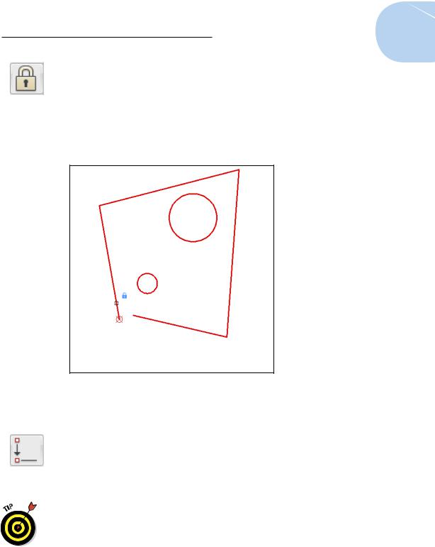
3.Click Fix in the Geometric panel and then click a point you want to fix in space.
A blue padlock icon is displayed beside the pickbox, and the red pick point marker appears when you’re over a point you can constrain (see Figure 19-3). In this example, we click one of the endpoints on the polyline. A padlock icon appears in the constraint bar, indicating that the endpoint of the polyline segment is fixed in place.
Figure 19-3: Locking down an object in drawing space.
With at least one point on the geometry fixed in place, you can start constraining the geometry by closing the gap in the linework.
4.Click Coincident in the Parametric tab’s Geometric panel.
You use a coincident constraint to make two points coincide. A blue coincident icon appears near the pickbox, and as you move your crosshairs over an object, a marker appears over relevant points — in the case of lines or polyline segments, at the endpoints and midpoint.
Use appropriate drawing commands based on your design intent. We use a polyline in this example because the ends of the segments are already coincident-constrained by being part of a single polyline object. If you had drawn this shape with lines, you’d have to apply individual coincident constraints to each corner.
www.it-ebooks.info
430 Part IV: Advancing with AutoCAD
5.Click an endpoint on the first polyline segment that you want to connect and then click an endpoint on the second segment.
The endpoint of the second polyline segment jumps to the endpoint of the first line, and a small blue square — the marker for coincident
constraints — appears at the intersection. (If you don’t see the little blue square, click Show All in the Geometric panel.)
6.Apply some orthographic parameters so that the linework starts to look a little more like a rectangle. Click Horizontal in the Parametric tab’s Geometric panel and then click a line or polyline segment that you want to be aligned with the drawing’s X axis.
In this example, we picked the bottom segment of the polyline. The segment realigns itself horizontally from the endpoint nearest to where you picked the line (unless a Fix constraint is added first), and a horizontal constraint marker — a constraint bar — appears near the object. A single item is still called the constraint bar because if you add additional constraints to the object, they get added to the existing one, like a toolbar.
7.Click Vertical to align a line or polyline segment with the drawing’s Y axis.
In this example, we pick the left vertical-ish polyline segment. The segment realigns itself at 90 degrees to the horizontal segment, and a constraint bar showing a vertical constraint appears. With one horizontally and one vertically constrained line segment, you’re halfway to a geometrically precise rectangle!
8.Because rectangles have parallel and perpendicular sides, next you apply those constraints to your linework. Click Parallel in the
Parametric tab’s Geometric panel, click the vertically constrained line segment, and then click the line segment opposite.
Because there’s already a vertical constraint applied to one segment, it doesn’t matter which line you pick first. If neither line had an existing constraint, the second line you picked would become parallel to the first line.
Always keep your design intent in mind as you think about which constraints to apply and when to apply them. As a general rule, start with the most important and drill down to the least important. And, as we remind you earlier in the chapter, applying a fix constraint early in the game can prevent your geometry rearranging itself in ways you don’t expect.
To make the final side of the almost-rectangle orthogonal with the other three, you could use another parallel constraint and click the bottom line. However, you don’t want to wear out our Parallel button, so use Perpendicular on the final segment.
www.it-ebooks.info
Chapter 19: Call the Parametrics! 431
9.Click Perpendicular on the Geometric panel, click either vertical side, and then click the non-orthogonal side.
Again, because three of the four sides are already constrained to horizontal and vertical, it doesn’t matter which segment you pick first.
“Perpendicular” means “at right angles to.” It isn’t restricted to “a vertical line going upward from one end of a horizontal line.” A line at an angle to the X axis can still be perpendicular to another.
Some constraints work on one object (horizontal, vertical), while others work on two objects (parallel, tangent, perpendicular). If you roll the cursor over a two-object constraint, its soul mate lights up.
To delete a constraint, move the mouse pointer over the constraint marker to display the constraints bar (see Figure 19-4), right-click, and choose Delete from the menu that appears.
Figure 19-4: Constraining to orthogonal.
From four non-orthogonal, not-even-closed line segments, applying a handful of constraints yields a perfect rectangle. However, you really want a square! Here’s where the Equal constraint comes in.
www.it-ebooks.info
432 Part IV: Advancing with AutoCAD
10.Click Equal on the Geometric panel, click the bottom side, and then click either of the vertical sides.
A perfect square! Now you want to constrain those circles.
The design intent in this example is to have the circles to be concentric and to locate their centers in the exact center of the rectangle. First the easy part: Making the circles concentric.
11.Click Concentric in the Geometric panel, click one circle, and then click the other.
The two circles are concentrically constrained (try saying that ten times in a hurry!), and a new constraint bar appears in their vicinity. Try moving one circle by clicking it and then watch the other tag along.
As we suggest, concentric was the easy constraint. We’d love to be able to use the Mid Between 2 Points object snap and just click two diagonally opposite corners to locate the circles dead center in the rectangle. However, because you can constrain only objects or points on objects, you have to add some construction geometry in order to maintain the design intent.
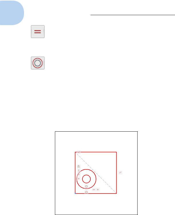
12.Draw a line between diagonally opposite corners by using Endpoint object snaps, and then apply coincident constraints between the endpoints of this line and the corners of the rectangle (see Figure 19-5).
Figure 19-5: Adding some construction geometry.
www.it-ebooks.info
Chapter 19: Call the Parametrics! 433
Draw construction geometry on a separate layer and set that layer to NoPlot in the Layer Properties Manager. If you don’t want to even see
it — let alone, not plot it — you can turn off your construction geometry layer or even freeze it — and the geometric constraints will still work.
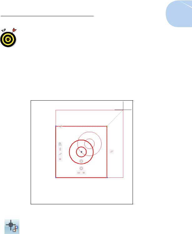
13.Click Coincident in the Geometric panel. Click either circle so that the parametric marker appears in the center, move the pickbox over the construction line, and click when the parametric marker is over the midpoint of the line.
You’re done! You can test your design intent by using the STRETCH command on the corner of the rectangle that doesn’t display a little square, blue coincident icon. As you drag the corner, you should see the two circles moving, too, always maintaining their position in the middle of the rectangle (see Figure 19-6).
Figure 19-6: Full-on geometric constraints.
Parametrics was a new feature in AutoCAD 2010, and it got a considerable enhancement in AutoCAD 2011 with the addition of inferred constraints. A status bar button (to the left of the Snap button) toggles Infer Constraints mode off and on. When Infer Constraints mode is enabled, you don’t have to specifically apply many of the geometric constraints.
www.it-ebooks.info