


Chapter 3: A Lap around the CAD Track 57
The step-by-step procedures in this chapter, unlike those in most chapters of this book, form a sequence. You must do the steps in order. Figuring out how to use AutoCAD is a little like figuring out how to drive, except that with AutoCAD, you’re free to stop in the middle of the street and take a break.
If you find that object selection or editing functions work differently from how we describe them in this chapter, you (or someone else) probably changed the configuration settings on the Option dialog box’s Selection tab. Chapter 10 describes these settings and how to restore the AutoCAD defaults.
A Simple Setup
In this chapter, we walk you through creating, editing, viewing, and plotting a new drawing — refer to Figure 3-1 if you want to get an idea of what the finished product looks like. You can follow these steps using either imperial l or metric units; we show metric values in brackets after the imperial ones, like this: Type 1.5 [38] and press Enter.
You can find the files we use in this sequence of steps at this book’s companion website. Go to www.dummies.com/go/autocad2013fd and download afd03.zip. The Zip file contains imperial and metric versions of the base plate exercise at various stages — the Read Me file on the downloads tab has a detailed description of the files.
Pay attention to AutoCAD’s feedback. Glance at the messages AutoCAD sends after each step via the command window at the bottom of the screen or the Dynamic Input tooltip near the crosshairs so that you begin to get familiar with the names of commands and their options. (If you don’t see any messages next to the crosshairs as you use the program, click the Dynamic Input button on the status bar — if your status bar displays button icons rather than text labels, click the button with the tooltip that reads “Dynamic Input.”) As we describe in Chapter 4, drawing setup sometimes isn’t a simple task in AutoCAD. Nonetheless, drawing setup is an important part of the job, and
if you don’t get in the habit of doing it right, you run into endless problems later on — especially when you try to plot. (See Chapter 16 for the lowdown on plotting your drawings.)
In this first set of steps, you create a new drawing from a template, change some settings to establish a 1:10 scale (that is, 1 inch or 1 millimeter on the drawing is equivalent to 10 inches or 10 millimeters on the real object), and save the drawing:
1.Start AutoCAD by double-clicking its shortcut on the Windows desktop.
If you don’t have an AutoCAD shortcut on your desktop, choose Start [All] Programs Autodesk AutoCAD 2013 AutoCAD 2013. (The last two will be AutoCAD LT 2013, if that’s your version.)
www.it-ebooks.info
58 Part I: AutoCAD 101
The workspaces in AutoCAD 2013 look very similar to one another. To make sure that you’re in the same workspace that we are, look at the Workspace label at the left side of the AutoCAD window’s title bar (if you’re running at a very low screen resolution, you may have to click the little arrow at the right of the Quick Access Toolbar). If it doesn’t say Drafting & Annotation, click the little black arrow on the button and then select Drafting & Annotation from the menu.
2.Click the Application button — that’s the big red A at the top left of the screen — to display the Application Menu. Then click New, or hover the mouse pointer over New and select Drawing.
(Don’t click the New button on the Quick Access Toolbar — use the menu. We explain why in Chapter 4, but just humor us for now.) The Select Template dialog box appears with a list of drawing templates (DWT files), which you can use as the starting point for new drawings. Templates in AutoCAD are like templates in Word and other programs. Chapter 4 describes how to create and use drawing templates.
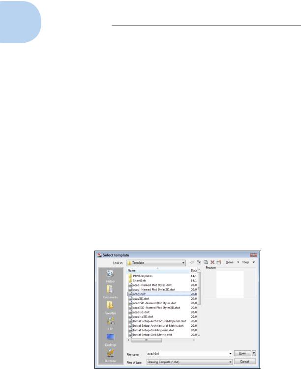
3.Select acad.dwt [acadiso.dwt], shown in Figure 3-2, and click Open. (For AutoCAD LT, select acadlt.dwt [acadltiso.dwt].)
AutoCAD creates a new, blank drawing that uses the settings in acad. dwt or acadiso.dwt. The acad.dwt template (acadlt.dwt in AutoCAD LT) is AutoCAD’s default, plain-Jane template for drawings in imperial units (units expressed in inches and/or feet). The acadiso.dwt (acadltiso.dwt in AutoCAD LT) template is the corresponding version for drawings created in metric units. Chapter 4 contains additional information about these and other templates.
Figure 3-2: Starting a new drawing from a template.
www.it-ebooks.info

Chapter 3: A Lap around the CAD Track 59
4.Click all the buttons on the left half of the status bar except Dynamic Input until they look dimmed (they’ll be gray instead of light blue). If your status bar displays button icons rather than text labels, click the button with the Dynamic Input tooltip.
Some of these settings can make selecting points difficult. It’s best to start with them all turned off and then toggle them on and off as needed. We tell you which ones to use in the steps that follow.
If your status-bar buttons show icons instead of text, right-click any button and click Use Icons to deselect the option and display text labels. You can leave them that way or right-click and select Use Icons again to toggle the icon display back on.
5.Type LIMITS and press Enter.
Drawing limits define your working area. AutoCAD prompts you to reset the model space limits. For now, ignore the Dynamic Input tooltip next to the crosshairs and look at the command window. The command line reads
Specify lower left corner or [ON/OFF] <0.0000,0.0000>:
6. Press Enter to keep 0,0 as the lower-left-corner value.
AutoCAD prompts for the upper-right corner. The command line reads
Specify upper right corner <12.0000,9.0000> or[<420.0000,297.0000>]if you started from the acadaiso.dwt template.:
7.Type 100,50 or [2750,1250] (no spaces) and press Enter.
AutoCAD echoes the values you enter at the command line.
100 x 50 corresponds to 10 inches by 5 inches (a little smaller than an 8.5-x-11-inch piece of paper turned on its long side) times a drawing scale factor of 10 (because you’re eventually going to plot at 1:10 scale). If you’re a metric maven, 2750 x 1250 corresponds to 275mm by 125mm (slightly smaller than an ISO A4 sheet turned lengthways) times a drawing scale factor of 10 (because you, too, will eventually plot at 1:10 scale). See Chapter 4 for more information about drawing scales.
To be honest, setting limits isn’t very important in AutoCAD anymore — modern computers can process much more data than they could in the 1980s when AutoCAD first appeared — but it does make it easier to plot a drawing from model space as you do in this chapter.
8.Right-click the Snap Mode button on the status bar and choose
Settings. If your status bar displays button icons rather than text labels, right-click the button with the Snap Mode tooltip.
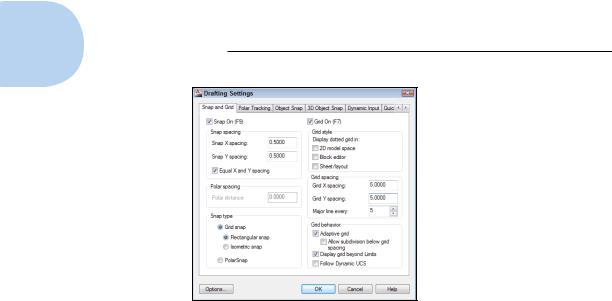
The Snap and Grid tab of the Drafting Settings dialog box appears, as shown in Figure 3-3. (Note that AutoCAD LT lacks some options that are present in the full version of AutoCAD.)
www.it-ebooks.info
60 Part I: AutoCAD 101
Figure 3-3: Snap and Grid settings.
9.Change the values in the dialog box so it looks like Figure 3-3:
•Snap On: Selected
Snap constrains your crosshairs to moving in an invisible grid of equally spaced points (0.5 [10] units apart in this case).
•Grid On: Selected
Grid displays a visible grid of little dots or grid lines on the screen (5 [100] units apart in this case), which you can use as reference points. The grid doesn’t appear on printed drawings.
•Snap X Spacing: 0.5 [10]
•Snap Y Spacing: 0.5 [10]
•Grid X Spacing: 5 [100]
•Grid Y Spacing: 5 [100]
10.Click OK.
You see a network of grid lines, 5 [100] units apart, in the drawing area. If you move your mouse pointer around and watch the coordinate display area at the left side of the status bar, you notice that the values still change in very small increments just as they did before. We have more on this in a moment.
11.Click the tiny down arrow below the Zoom button (the one with the magnifying glass) on the Navigation bar (at the right edge of the drawing area in Figure 3-1), and then choose Zoom All from the menu.
AutoCAD zooms out so that the entire area defined by the limits is visible.
www.it-ebooks.info