

Chapter 3: A Lap around the CAD Track 61
12.Click the Save button on the Quick Access Toolbar or press Ctrl+S.
Because you haven’t saved the drawing yet, AutoCAD opens the Save Drawing As dialog box.
13.Navigate to a suitable folder by choosing from the Save In drop-down list and/or double-clicking folders in the list of folders below it.
Remember where you save the file so you can go back to it later.
14.Type a name in the File Name text box and click Save. For example, type Detail or My Plate is Base.
Depending on your Windows Explorer settings, you may or may not see the .dwg extension in the File Name text box. In any case, you don’t need to type it. AutoCAD adds it for you.
AutoCAD saves the new DWG file to the folder you specified in Step 13.
Whew — that was more work than digging a post-hole — and all just to set up a simple drawing! Chapter 4 goes into more detail about drawing setup and describes why all these gyrations are necessary, and how to avoid doing them more than once by defining your own template files.
Drawing a (Base) Plate
With a properly set up drawing, you’re ready to draw some objects. In this example, you use the RECTANG command to draw a steel base plate and column, the CIRCLE command to draw an anchor bolt, and the POLYGON command to draw a hexagonal nut. (Both the RECTANG and POLYGON commands create polylines — objects that contain a series of straight-line segments and/or arc segments.) We describe these drawing commands in more detail in Chapters 8 and 9.
AutoCAD, like most CAD programs, uses layers as an organizing principle for all the objects that you draw. Chapter 6 describes layers and other object properties in detail. In this example, you create separate layers for the base plate, column, anchor bolts, and nuts. This might seem like layer madness, but when you’re doing complex drawings, you need to use a lot of layers just to keep things organized.
Drawing rectangles on the right layers
The following steps demonstrate how to create and use layers, as well as how to draw rectangles. You also see how to apply fillets to objects and offset them. (Chapter 6 describes layers in detail, and Chapter 8 covers the RECTANG command. Chapter 11 explains the FILLET and OFFSET commands.)
www.it-ebooks.info
62 Part I: AutoCAD 101
Start by creating a Column layer and a Plate layer and then drawing a rectangular column on the Column layer and a square base plate on the Plate layer:
1.Make sure that you complete the drawing set up in the previous section of this chapter and have the drawing open in AutoCAD.
2.Click the Home tab on the Ribbon.
You’ll find the most frequently used commands for 2D drafting tasks on the Ribbon’s Home tab. (For a refresher on the contents of the other tabs, refer to the “Unraveling the Ribbon” section in Chapter 2.) Unless we direct you otherwise, look on the Home tab for the panels and buttons we specify in the following steps.
3.On the Layers panel, click the Layer Properties button.
The Layer Properties button is at the upper-left corner of the Layers panel. The LAYER command starts, and AutoCAD displays the Layer Properties Manager palette.
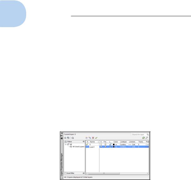
4.Click the New Layer button.
AutoCAD adds a new layer to the list and gives it the default name Layer1 (see Figure 3-4).
Figure 3-4: Creating a new layer.
5.Type a more suitable name for the layer on which you’ll draw the column and press Enter.
For this example, type Column.
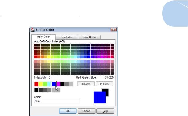
6.Click the color swatch or name (white) in the Column layer row.
The Select Color dialog box appears (see Figure 3-5).
www.it-ebooks.info
Chapter 3: A Lap around the CAD Track 63
Figure 3-5: Blue is the color — select it from the standard color tiles.
7.Click color 5 (blue) in the single, separate row to the left of the ByLayer and ByBlock buttons, and then click OK.
The Select Color dialog box closes, and AutoCAD changes the color of the Column layer to blue.
8.With the Layer Properties Manager still open, repeat Steps 4 through 7 to create a new layer named Plate and set its color to 4 (cyan, or light blue).
9.With layer Plate still highlighted, click the Set Current button (the green check mark).
Plate becomes the current layer, and everything you draw is placed on that layer until you set a different layer current.
10.Click Close (the “X” at the top-left corner of the palette in Figure 3-4) to close the Layer Properties Manager palette.
The Layer drop-down list on the Home tab’s Layers panel displays Plate as the current layer. Now you can draw a rectangular plate on the Plate layer.
You probably already know that the RECTANG command will draw a rectangular plate for you, but for the next step, pretend that you don’t.
www.it-ebooks.info

64 Part I: AutoCAD 101
If you want to cheat a bit, you can start from this point with drawing afd03a-i.dwg [afd03a-m.dwg] available in the afd03.zip download at www.dummies.com/go/autocad2013fd. Download it to a suitable location and then click the Application button and then Open. Browse to the file.
11.Start typing RECT . . .
As you type, AutoCAD guesses what you might be looking for. When you type enough letters, the command you’re probably looking for appears at or near the top of the list that appears.
12.When “Rectangle” appears in the list, simply click it. In our case, it happens to be the first item in the list, so we can press Enter or the spacebar instead of clicking it.
The RECTANG command starts, and AutoCAD prompts you to specify the first corner point. The command line shows
Specify first corner point or [Chamfer/Elevation/ Fillet/Thickness/Width]:
13.Click in the drawing area at the point 32,7 [800,175].
By watching the coordinate display on the Dynamic Input tooltip, you can see the coordinates of the current crosshairs location. Because Snap Mode is set to 0.5 [10] units, you can land right on the point 32,7 [800,175]. Picking the first corner in this location gives you enough room to work.
In previous releases, the cursor jumps to the snap spacing whenever Snap mode is active, but this can cause other inconveniences. In AutoCAD 2013, it jumps to the snap interval only when a command is active that is asking for a point or a distance.
AutoCAD prompts at the command line
Specify other corner point or [Area/Dimensions/Rotation]:
14.Type 36,36 [900,900] (without any spaces) and press Enter.
Make sure that the Dynamic Input button is on for this step. If it’s not, AutoCAD treats an input of 36,36 as absolute coordinates — that is, 36 units above and 36 units to the right of the origin. When Dynamic Input is on, an input of 36,36 is treated as 36 units above and 36 units to the right of the last point — in other words, as relative to the last point. See Chapter 7 for more information about typing absolute and relative coordinates.
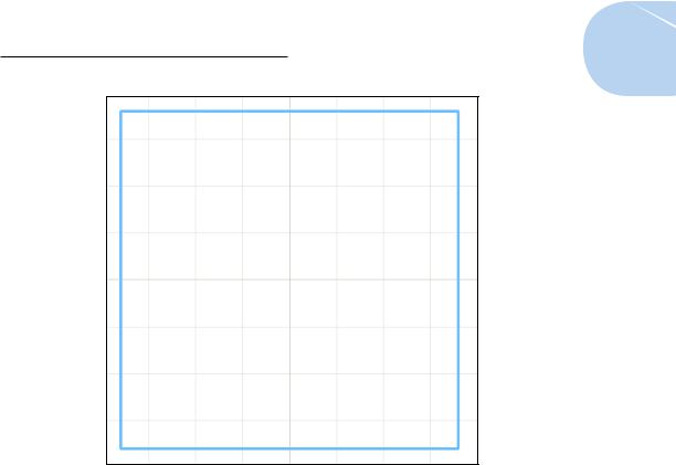
AutoCAD draws the 36 x 36 [900 x 900] rectangle, as shown in Figure 3-6. It’s on the Plate layer and inherits that layer’s cyan color.
You draw the column next, but first you have to change layers.
www.it-ebooks.info
Chapter 3: A Lap around the CAD Track 65
Figure 3-6: Your (base) plate is empty.
15.On the Layers panel of the Home tab, click the Layer drop-down list to display the list of layers. Click Column to set it as the current layer.
Using the Layer drop-down list saves you from having to open the Layer Properties Manager, select the layer, and click the Set Current button. Becoming an AutoCAD master is all about efficiency!
16.Right-click in an empty area of the screen to display the shortcut menu. Choose Repeat RECTANG to draw another rectangle.
In the next steps, you create a hollow steel column.
17.At the Specify First Corner Point prompt, type 44,16 [1100,400] and press Enter. Be sure to keep your cursor in the drawing area during this step and the next one.
18.At the Specify Other Corner Point prompt, type 12,18 [300,450] and press Enter.
A second rectangle is drawn in the middle of the base plate.
Next, you round the corners of the column with the FILLET command and then use OFFSET to give it some thickness.
19.On the Home tab’s Modify panel, click the Fillet button.
www.it-ebooks.info

66 Part I: AutoCAD 101
The FILLET command starts, and AutoCAD prompts you to select the first object. Look at the command line to see the options for this command. In the next step, you specify a 2-inch [50mm] radius fillet to all four corners.
20.Type R and press Enter to set a new fillet radius. Type 2 [50] and press Enter.
AutoCAD again prompts you to select the first object. You could pick each of the lines at each corner that need to be filleted (that’s eight picks), but because the column is a continuous polyline, in this case a more efficient method is to use the FILLET command’s Polyline option to fillet all four corners in one fell swoop.
21.Type P to choose the Polyline option, and then press Enter.
AutoCAD prompts you to select a 2D polyline. As you move your mouse pointer over the rectangle, AutoCAD shows you a preview of what the fillet will look like.
22.Select the rectangle you drew in Steps 16 to 18.
All four corners of the column are rounded with a 2-inch [50mm] radius fillet.
Next, offset the polyline to create a 3⁄4-inch [19mm] thick steel column.
23.On the Modify panel, click the Offset button.
24. At the Specify Offset Distance prompt, type .75 [19] and press Enter.
Make sure that your Object Snap status bar button is toggled off for the next step, or AutoCAD may offset your object back on top of itself.
25.At the Select Object to Offset prompt, click the rounded rectangle. At the Specify Point on Side to Offset prompt, click anywhere inside the rounded rectangle. Press Enter to complete the command.
AutoCAD offsets the selected object toward the inside of the rounded rectangle (see Figure 3-7).
26.Click the Dynamic Input button on the status bar so the button looks dimmed.
Now that you’ve given Dynamic Input a test drive, turn it off for the rest of this chapter. You know how to turn it off and on, and if you like it, by all means, turn it on again for the remainder of the book. Personally, we think that it gets in the way too much to be truly useful, so we rarely use it.
27.Press Ctrl+S to save the drawing.
AutoCAD saves the drawing and renames the previously saved version drawingname.bak — for example, My Plate is Base.bak. .bak is AutoCAD’s extension for a backup file. When (not “if”) things get out of hand, you can always rename the .bak file to .dwg to go back to the earlier version.
www.it-ebooks.info