

- •About the Authors
- •Dedication
- •Authors’ Acknowledgments
- •Table of Contents
- •Introduction
- •What’s Not (And What Is) in This Book
- •Mac attack!
- •Who Do We Think You Are?
- •How This Book Is Organized
- •Part I: AutoCAD 101
- •Part II: Let There Be Lines
- •Part III: If Drawings Could Talk
- •Part IV: Advancing with AutoCAD
- •Part V: On a 3D Spree
- •Part VI: The Part of Tens
- •But wait . . . there’s more!
- •Icons Used in This Book
- •A Few Conventions — Just in Case
- •Commanding from the keyboard
- •Tying things up with the Ribbon
- •Where to Go from Here
- •Why AutoCAD?
- •The Importance of Being DWG
- •Seeing the LT
- •Checking System Requirements
- •Suddenly, It’s 2013!
- •AutoCAD Does Windows (And Office)
- •And They’re Off: AutoCAD’s Opening Screens
- •Running with Ribbons
- •Getting with the Program
- •Looking for Mr. Status Bar
- •Let your fingers do the talking: The command window
- •The key(board) to AutoCAD success
- •Keeping tabs on palettes
- •Down the main stretch: The drawing area
- •Fun with F1
- •A Simple Setup
- •Drawing a (Base) Plate
- •Drawing rectangles on the right layers
- •Circling your plate
- •Nuts to you
- •Getting a Closer Look with Zoom and Pan
- •Modifying to Make It Merrier
- •Hip-hip-array!
- •Stretching out
- •Crossing your hatches
- •Following the Plot
- •A Setup Roadmap
- •Choosing your units
- •Weighing up your scales
- •Thinking annotatively
- •Thinking about paper
- •Defending your border
- •A Template for Success
- •Making the Most of Model Space
- •Setting your units
- •Making the drawing area snap-py (and grid-dy)
- •Setting linetype and dimension scales
- •Entering drawing properties
- •Making Templates Your Own
- •Setting Up a Layout in Paper Space
- •Will that be tabs or buttons?
- •View layouts Quick(View)ly
- •Creating a layout
- •Copying and changing layouts
- •Lost in paper space
- •Spaced out
- •A view(port) for drawing in
- •About Paper Space Layouts and Plotting
- •Managing Your Properties
- •Layer one on me!
- •Accumulating properties
- •Creating new layers
- •Manipulating layers
- •Using Named Objects
- •Using AutoCAD DesignCenter
- •Copying layers between drawings
- •Controlling Your Precision
- •Keyboard capers: Coordinate input
- •Understanding AutoCAD’s coordinate systems
- •Grab an object and make it snappy
- •Other Practical Precision Procedures
- •Introducing the AutoCAD Drawing Commands
- •The Straight and Narrow: Lines, Polylines, and Polygons
- •Toeing the line
- •Connecting the lines with polyline
- •Squaring off with rectangles
- •Choosing your sides with polygon
- •(Throwing) Curves
- •Going full circle
- •Arc-y-ology
- •Solar ellipses
- •Splines: The sketchy, sinuous curves
- •Donuts: The circles with a difference
- •Revision clouds on the horizon
- •Scoring Points
- •Commanding and Selecting
- •Command-first editing
- •Selection-first editing
- •Direct object manipulation
- •Choosing an editing style
- •Grab It
- •One-by-one selection
- •Selection boxes left and right
- •Perfecting Selecting
- •AutoCAD Groupies
- •Object Selection: Now You See It . . .
- •Get a Grip
- •About grips
- •A gripping example
- •Move it!
- •Copy, or a kinder, gentler Move
- •A warm-up stretch
- •Your AutoCAD Toolkit
- •The Big Three: Move, Copy, and Stretch
- •Base points and displacements
- •Move
- •Copy
- •Copy between drawings
- •Stretch
- •More Manipulations
- •Mirror
- •Rotate
- •Scale
- •Array
- •Offset
- •Slicing, Dicing, and Splicing
- •Trim and Extend
- •Break
- •Fillet and Chamfer and Blend
- •Join
- •When Editing Goes Bad
- •Zoom and Pan with Glass and Hand
- •The wheel deal
- •Navigating your drawing
- •Controlling your cube
- •Time to zoom
- •A View by Any Other Name . . .
- •Looking Around in Layout Land
- •Degenerating and Regenerating
- •Getting Ready to Write
- •Simply stylish text
- •Taking your text to new heights
- •One line or two?
- •Your text will be justified
- •Using the Same Old Line
- •Turning On Your Annotative Objects
- •Saying More in Multiline Text
- •Making it with Mtext
- •It slices; it dices . . .
- •Doing a number on your Mtext lists
- •Line up in columns — now!
- •Modifying Mtext
- •Gather Round the Tables
- •Tables have style, too
- •Creating and editing tables
- •Take Me to Your Leader
- •Electing a leader
- •Multi options for multileaders
- •How Do You Measure Up?
- •A Field Guide to Dimensions
- •The lazy drafter jumps over to the quick dimension commands
- •Dimension associativity
- •Where, oh where, do my dimensions go?
- •The Latest Styles in Dimensioning
- •Creating and managing dimension styles
- •Let’s get stylish!
- •Adjusting style settings
- •Size Matters
- •Details at other scales
- •Editing Dimensions
- •Editing dimension geometry
- •Editing dimension text
- •Controlling and editing dimension associativity
- •Batten Down the Hatches!
- •Don’t Count Your Hatches. . .
- •Size Matters!
- •We can do this the hard way. . .
- •. . . or we can do this the easy way
- •Annotative versus non-annotative
- •Pushing the Boundary (Of) Hatch
- •Your hatching has no style!
- •Hatch from scratch
- •Editing Hatch Objects
- •You Say Printing, We Say Plotting
- •The Plot Quickens
- •Plotting success in 16 steps
- •Get with the system
- •Configure it out
- •Preview one, two
- •Instead of fit, scale it
- •Plotting the Layout of the Land
- •Plotting Lineweights and Colors
- •Plotting with style
- •Plotting through thick and thin
- •Plotting in color
- •It’s a (Page) Setup!
- •Continuing the Plot Dialog
- •The Plot Sickens
- •Rocking with Blocks
- •Creating Block Definitions
- •Inserting Blocks
- •Attributes: Fill-in-the-Blank Blocks
- •Creating attribute definitions
- •Defining blocks that contain attribute definitions
- •Inserting blocks that contain attribute definitions
- •Edit attribute values
- •Extracting data
- •Exploding Blocks
- •Purging Unused Block Definitions
- •Arraying Associatively
- •Comparing the old and new ARRAY commands
- •Hip, hip, array!
- •Associatively editing
- •Going External
- •Becoming attached to your xrefs
- •Layer-palooza
- •Creating and editing an external reference file
- •Forging an xref path
- •Managing xrefs
- •Blocks, Xrefs, and Drawing Organization
- •Mastering the Raster
- •Attaching a raster image
- •Maintaining your image
- •Theme and Variations: Dynamic Blocks
- •Lights! Parameters!! Actions!!!
- •Manipulating dynamic blocks
- •Maintaining Design Intent
- •Defining terms
- •Forget about drawing with precision!
- •Constrain yourself
- •Understanding Geometric Constraints
- •Applying a little more constraint
- •AutoConstrain yourself!
- •Understanding Dimensional Constraints
- •Practice a little constraint
- •Making your drawing even smarter
- •Using the Parameters Manager
- •Dimensions or constraints — have it both ways!
- •The Internet and AutoCAD: An Overview
- •You send me
- •Send it with eTransmit
- •Rapid eTransmit
- •Bad reception?
- •Help from the Reference Manager
- •Design Web Format — Not Just for the Web
- •All about DWF and DWFx
- •Autodesk Design Review 2013
- •The Drawing Protection Racket
- •Autodesk Weather Forecast: Increasing Cloud
- •Working Solidly in the Cloud
- •Free AutoCAD!
- •Going once, going twice, going 123D
- •Your head planted firmly in the cloud
- •The pros
- •The cons
- •Cloudy with a shower of DWGs
- •AutoCAD 2013 cloud connectivity
- •Tomorrow’s Forecast
- •Understanding 3D Digital Models
- •Tools of the Trade
- •Warp speed ahead
- •Entering the third dimension
- •Untying the Ribbon and opening some palettes
- •Modeling from Above
- •Using 3D coordinate input
- •Using point filters
- •Object snaps and object snap tracking
- •Changing Planes
- •Displaying the UCS icon
- •Adjusting the UCS
- •Navigating the 3D Waters
- •Orbit à go-go
- •Taking a spin around the cube
- •Grabbing the SteeringWheels
- •Visualizing 3D Objects
- •Getting Your 3D Bearings
- •Creating a better 3D template
- •Seeing the world from new viewpoints
- •From Drawing to Modeling in 3D
- •Drawing basic 3D objects
- •Gaining a solid foundation
- •Drawing solid primitives
- •Adding the Third Dimension to 2D Objects
- •Creating 3D objects from 2D drawings
- •Modifying 3D Objects
- •Selecting subobjects
- •Working with gizmos
- •More 3D variants of 2D commands
- •Editing solids
- •Get the 2D Out of Here!
- •A different point of view
- •But wait! There’s more!
- •But wait! There’s less!
- •Do You See What I See?
- •Visualizing the Digital World
- •Adding Lighting
- •Default lighting
- •User-defined lights
- •Sunlight
- •Creating and Applying Materials
- •Defining a Background
- •Rendering a 3D Model
- •Autodesk Feedback Community
- •Autodesk Discussion Groups
- •Autodesk’s Own Bloggers
- •Autodesk University
- •The Autodesk Channel on YouTube
- •The World Wide (CAD) Web
- •Your Local ATC
- •Your Local User Group
- •AUGI
- •Books
- •Price
- •3D Abilities
- •Customization Options
- •Network Licensing
- •Express Tools
- •Parametrics
- •Standards Checking
- •Data Extraction
- •MLINE versus DLINE
- •Profiles
- •Reference Manager
- •And The Good News Is . . .
- •APERTURE
- •DIMASSOC
- •MENUBAR
- •MIRRTEXT
- •OSNAPZ
- •PICKBOX
- •REMEMBERFOLDERS
- •ROLLOVERTIPS
- •TOOLTIPS
- •VISRETAIN
- •And the Bonus Round
- •Index
Chapter 17: The ABCs of Blocks 375
•If you select the Convert to Block radio button (the default) in Step 5, AutoCAD creates a block reference pointing to the new block definition. The objects look the same onscreen, but they are now an instance of the block rather than the original, separate objects. Most of the time, this is your best choice.
•If you select the Retain radio button, the objects remain in place but aren’t converted into a block reference. They remain individual objects with no connection to the new block definition.
•If you select the Delete radio button, the objects disappear, but the block definition still gets created.
When you define a block, you can include a special kind of variable text object called an attribute definition. When you insert a block that contains one or more attribute definitions, AutoCAD prompts you to fill in values for the text fields. Attributes are useful for things like variable title block information (sheet number, sheet title, and so on), electric motor nameplate information, and symbols that contain different codes or callouts. We describe how to create and use attribute definitions later in this chapter.
Keep your common symbol drawings in one or more specific folders that you set aside just for that purpose. You may want to use one of the following techniques to develop a library of symbols that you use frequently:
Create a separate DWG file for each block.
Store a bunch of symbols as block definitions in one drawing and use DesignCenter to import block definitions from this drawing when you need them.
If you have a block definition in one drawing that you would like to use in other drawings, use the WBLOCK (WriteBlock) command to extract and write a copy of it out to disk as a new DWG file and then insert it into other drawings as required.
Inserting Blocks
AutoCAD provides a number of ways to insert a block or a whole drawing file, but the most commonly used and most flexible is the Insert dialog box. Here’s the procedure for inserting a block:
1. Set an appropriate layer current, as described in Chapter 6.
Insert each block on a layer that has something to do with the block’s geometry or purpose:
www.it-ebooks.info
376 Part IV: Advancing with AutoCAD
•If all the objects in the block definition reside on one layer, it’s usually best to insert the block on that layer.
•If the block geometry spans several layers, choose one of them to insert the block on.
If any of the block definition’s geometry was created on Layer 0, that geometry will inherit the color, linetype, and other object properties of the layer on which you insert the block. It’s like the chameleon changing color to match its surroundings or a politician changing his position to match the day’s opinion polls.
2.On the Ribbon’s Home tab, click the Insert button on the Block panel.
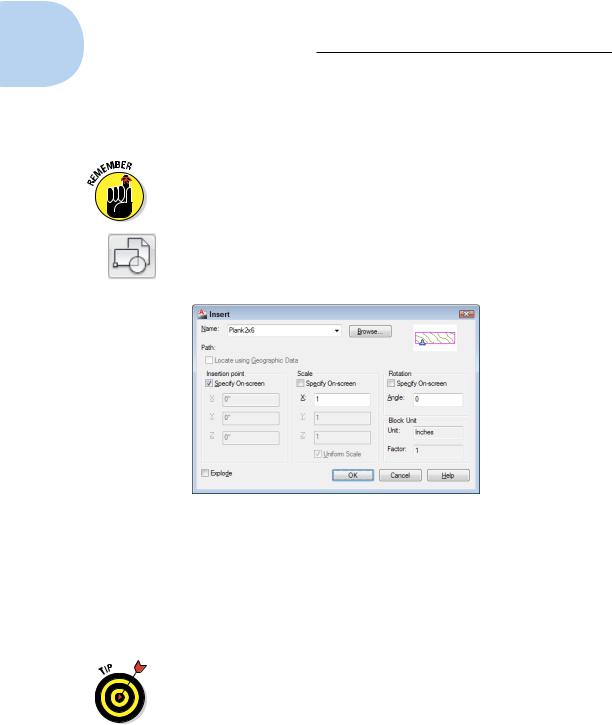
The Insert dialog box appears, as shown in Figure 17-3.
Figure 17-3: The Insert dialog box.
3.Enter the block definition name (or external filename) by using one of the following methods:
•Use the Name drop-down list to select from a list of block definitions in the current drawing.
•Click the Browse button to select an external DWG file and have AutoCAD create a block definition from it.
You can browse to any existing drawing and insert it into the current drawing. This creates a new block definition within the host drawing. The new definition doesn’t retain any connection at all to the inserted drawing.
You can use an external drawing to replace a block definition in your current drawing. If you click Browse and choose a file whose name matches the name of a block definition that’s already in your drawing,
www.it-ebooks.info
Chapter 17: The ABCs of Blocks 377
AutoCAD asks you to confirm the update and, if you agree, updates the block definition in your drawing with the current contents of the external file. This process is block redefinition, and AutoCAD automatically updates all block references that point to the block definition.
4. Enter the insertion point, scale, and rotation angle of the block.
You can either select the Specify On-Screen check box in each area to specify the parameters onscreen at the command prompt; or type the values you want in the text boxes in the Insertion Point, Scale, and Rotation areas.
Select the Uniform Scale check box to constrain the X, Y, and Z scal- ing parameters to the same value (which is what you want in almost all cases).
5.If you want AutoCAD to create a copy of the individual objects in the block instead of a block reference that points to the block definition, select the Explode check box and click OK.
6.If you selected the Specify On-Screen check box for the insertion point, scale, or rotation angle, answer the prompts on the command line to specify these parameters.
After you insert a block, all the objects displayed in the block reference behave as a single object. When you select any object in the block reference, AutoCAD highlights all the objects in it.
Another way to insert a block is to drag a DWG file from Windows Explorer and drop it anywhere in the current drawing window. AutoCAD then prompts you to choose an insertion point and optionally change the default scale factor and rotation angle. Similarly, you can drag a block definition from the Blocks section of the DesignCenter palette and drop it into the current drawing window. (Chapter 6 describes DesignCenter.)
You can now import Inventor part (.IPT) and assembly (.IAM) models directly into AutoCAD 2013. Inventor is AutoCAD’s 3D parametric and associative sibling, intended primarily for mechanical design. Imported Inventor files come across as dumb 3D solids that lose their parametrics and associativity, but they can be modified and edited like any other AutoCAD 3D solid. We cover AutoCAD’s 2D parametrics in Chapter 19, and introduce you to 3D modeling in Chapters 21 through 23.
AutoCAD provides one additional way of inserting blocks: the Tool Palettes window, which we describe in Chapter 2. As is true of using a tool palette for hatching (Chapter 15), you first must create and configure appropriate tools. The easiest method is right-clicking a drawing in DesignCenter and choosing Create Tool Palette. A new tabbed page is added to the Tool Palettes window,
www.it-ebooks.info
378 Part IV: Advancing with AutoCAD
containing all the block definitions from the drawing that you right-clicked. Simply click and drag a tool to insert its corresponding block into a drawing.
Dragging blocks from a tool palette doesn’t give you the chance to specify a different insertion scale, nor can you use all AutoCAD’s precision tools to
specify the insertion point precisely — you may need to move the block into place after inserting it. We recommend that you first master the other block insertion methods described in this chapter — especially using the Insert dialog box and DesignCenter palette. Then if you find yourself inserting the same blocks frequently, consider creating a tool palette containing them. Check out “Add Content with DesignCenter” in the AutoCAD online help system for more information.
Although the preceding paragraph refers to the Tool Palettes window, palettes in AutoCAD are not like regular windows or dialog boxes. They are modeless, which means that they can stay open while you carry on with other tasks outside them. The official programmer-ese term for palettes is enhanced secondary window, or ESW for short. (We think we’re sticking with
palettes.)
Be careful when you insert one drawing into another. If the host (or parent) drawing and the inserted (or child) drawing have different definitions for layers that share the same name, the objects in the inserted drawing take on the layer characteristics of the host drawing. For example, if you insert a drawing with lines on a layer called Walls that’s blue and dashed into a drawing with a layer called Walls that’s red and continuous, the inserted lines on the Wall layer will turn red and continuous after they’re inserted. The same
rules apply to linetypes, text styles, dimension styles, table styles, multileader styles, and block definitions that are nested inside the drawing you’re inserting. As you probably remember from when you were little . . . parents rule!
If you need to modify a block definition after you’ve inserted one or more instances of it, use the Block Editor (BEDIT command); choose Block Editor on the Home tab’s Block panel. Look up BEDIT in the AutoCAD online help system.
Locate Using Geographic Data is an option in AutoCAD’s Insert dialog box. Geographic data refers to locating drawing geometry with reference to specific locations on planet Earth (so far) defined in one of a number of recognized global coordinate systems. This feature promises to be very big in the civil engineering community, or possibly for very large architectural projects, where a ground-based coordinate system is in place. If it sounds like something you need, look in the online help (and visit your local dealer or training center for further direction).
www.it-ebooks.info