

- •About the Authors
- •Dedication
- •Authors’ Acknowledgments
- •Table of Contents
- •Introduction
- •What’s Not (And What Is) in This Book
- •Mac attack!
- •Who Do We Think You Are?
- •How This Book Is Organized
- •Part I: AutoCAD 101
- •Part II: Let There Be Lines
- •Part III: If Drawings Could Talk
- •Part IV: Advancing with AutoCAD
- •Part V: On a 3D Spree
- •Part VI: The Part of Tens
- •But wait . . . there’s more!
- •Icons Used in This Book
- •A Few Conventions — Just in Case
- •Commanding from the keyboard
- •Tying things up with the Ribbon
- •Where to Go from Here
- •Why AutoCAD?
- •The Importance of Being DWG
- •Seeing the LT
- •Checking System Requirements
- •Suddenly, It’s 2013!
- •AutoCAD Does Windows (And Office)
- •And They’re Off: AutoCAD’s Opening Screens
- •Running with Ribbons
- •Getting with the Program
- •Looking for Mr. Status Bar
- •Let your fingers do the talking: The command window
- •The key(board) to AutoCAD success
- •Keeping tabs on palettes
- •Down the main stretch: The drawing area
- •Fun with F1
- •A Simple Setup
- •Drawing a (Base) Plate
- •Drawing rectangles on the right layers
- •Circling your plate
- •Nuts to you
- •Getting a Closer Look with Zoom and Pan
- •Modifying to Make It Merrier
- •Hip-hip-array!
- •Stretching out
- •Crossing your hatches
- •Following the Plot
- •A Setup Roadmap
- •Choosing your units
- •Weighing up your scales
- •Thinking annotatively
- •Thinking about paper
- •Defending your border
- •A Template for Success
- •Making the Most of Model Space
- •Setting your units
- •Making the drawing area snap-py (and grid-dy)
- •Setting linetype and dimension scales
- •Entering drawing properties
- •Making Templates Your Own
- •Setting Up a Layout in Paper Space
- •Will that be tabs or buttons?
- •View layouts Quick(View)ly
- •Creating a layout
- •Copying and changing layouts
- •Lost in paper space
- •Spaced out
- •A view(port) for drawing in
- •About Paper Space Layouts and Plotting
- •Managing Your Properties
- •Layer one on me!
- •Accumulating properties
- •Creating new layers
- •Manipulating layers
- •Using Named Objects
- •Using AutoCAD DesignCenter
- •Copying layers between drawings
- •Controlling Your Precision
- •Keyboard capers: Coordinate input
- •Understanding AutoCAD’s coordinate systems
- •Grab an object and make it snappy
- •Other Practical Precision Procedures
- •Introducing the AutoCAD Drawing Commands
- •The Straight and Narrow: Lines, Polylines, and Polygons
- •Toeing the line
- •Connecting the lines with polyline
- •Squaring off with rectangles
- •Choosing your sides with polygon
- •(Throwing) Curves
- •Going full circle
- •Arc-y-ology
- •Solar ellipses
- •Splines: The sketchy, sinuous curves
- •Donuts: The circles with a difference
- •Revision clouds on the horizon
- •Scoring Points
- •Commanding and Selecting
- •Command-first editing
- •Selection-first editing
- •Direct object manipulation
- •Choosing an editing style
- •Grab It
- •One-by-one selection
- •Selection boxes left and right
- •Perfecting Selecting
- •AutoCAD Groupies
- •Object Selection: Now You See It . . .
- •Get a Grip
- •About grips
- •A gripping example
- •Move it!
- •Copy, or a kinder, gentler Move
- •A warm-up stretch
- •Your AutoCAD Toolkit
- •The Big Three: Move, Copy, and Stretch
- •Base points and displacements
- •Move
- •Copy
- •Copy between drawings
- •Stretch
- •More Manipulations
- •Mirror
- •Rotate
- •Scale
- •Array
- •Offset
- •Slicing, Dicing, and Splicing
- •Trim and Extend
- •Break
- •Fillet and Chamfer and Blend
- •Join
- •When Editing Goes Bad
- •Zoom and Pan with Glass and Hand
- •The wheel deal
- •Navigating your drawing
- •Controlling your cube
- •Time to zoom
- •A View by Any Other Name . . .
- •Looking Around in Layout Land
- •Degenerating and Regenerating
- •Getting Ready to Write
- •Simply stylish text
- •Taking your text to new heights
- •One line or two?
- •Your text will be justified
- •Using the Same Old Line
- •Turning On Your Annotative Objects
- •Saying More in Multiline Text
- •Making it with Mtext
- •It slices; it dices . . .
- •Doing a number on your Mtext lists
- •Line up in columns — now!
- •Modifying Mtext
- •Gather Round the Tables
- •Tables have style, too
- •Creating and editing tables
- •Take Me to Your Leader
- •Electing a leader
- •Multi options for multileaders
- •How Do You Measure Up?
- •A Field Guide to Dimensions
- •The lazy drafter jumps over to the quick dimension commands
- •Dimension associativity
- •Where, oh where, do my dimensions go?
- •The Latest Styles in Dimensioning
- •Creating and managing dimension styles
- •Let’s get stylish!
- •Adjusting style settings
- •Size Matters
- •Details at other scales
- •Editing Dimensions
- •Editing dimension geometry
- •Editing dimension text
- •Controlling and editing dimension associativity
- •Batten Down the Hatches!
- •Don’t Count Your Hatches. . .
- •Size Matters!
- •We can do this the hard way. . .
- •. . . or we can do this the easy way
- •Annotative versus non-annotative
- •Pushing the Boundary (Of) Hatch
- •Your hatching has no style!
- •Hatch from scratch
- •Editing Hatch Objects
- •You Say Printing, We Say Plotting
- •The Plot Quickens
- •Plotting success in 16 steps
- •Get with the system
- •Configure it out
- •Preview one, two
- •Instead of fit, scale it
- •Plotting the Layout of the Land
- •Plotting Lineweights and Colors
- •Plotting with style
- •Plotting through thick and thin
- •Plotting in color
- •It’s a (Page) Setup!
- •Continuing the Plot Dialog
- •The Plot Sickens
- •Rocking with Blocks
- •Creating Block Definitions
- •Inserting Blocks
- •Attributes: Fill-in-the-Blank Blocks
- •Creating attribute definitions
- •Defining blocks that contain attribute definitions
- •Inserting blocks that contain attribute definitions
- •Edit attribute values
- •Extracting data
- •Exploding Blocks
- •Purging Unused Block Definitions
- •Arraying Associatively
- •Comparing the old and new ARRAY commands
- •Hip, hip, array!
- •Associatively editing
- •Going External
- •Becoming attached to your xrefs
- •Layer-palooza
- •Creating and editing an external reference file
- •Forging an xref path
- •Managing xrefs
- •Blocks, Xrefs, and Drawing Organization
- •Mastering the Raster
- •Attaching a raster image
- •Maintaining your image
- •Theme and Variations: Dynamic Blocks
- •Lights! Parameters!! Actions!!!
- •Manipulating dynamic blocks
- •Maintaining Design Intent
- •Defining terms
- •Forget about drawing with precision!
- •Constrain yourself
- •Understanding Geometric Constraints
- •Applying a little more constraint
- •AutoConstrain yourself!
- •Understanding Dimensional Constraints
- •Practice a little constraint
- •Making your drawing even smarter
- •Using the Parameters Manager
- •Dimensions or constraints — have it both ways!
- •The Internet and AutoCAD: An Overview
- •You send me
- •Send it with eTransmit
- •Rapid eTransmit
- •Bad reception?
- •Help from the Reference Manager
- •Design Web Format — Not Just for the Web
- •All about DWF and DWFx
- •Autodesk Design Review 2013
- •The Drawing Protection Racket
- •Autodesk Weather Forecast: Increasing Cloud
- •Working Solidly in the Cloud
- •Free AutoCAD!
- •Going once, going twice, going 123D
- •Your head planted firmly in the cloud
- •The pros
- •The cons
- •Cloudy with a shower of DWGs
- •AutoCAD 2013 cloud connectivity
- •Tomorrow’s Forecast
- •Understanding 3D Digital Models
- •Tools of the Trade
- •Warp speed ahead
- •Entering the third dimension
- •Untying the Ribbon and opening some palettes
- •Modeling from Above
- •Using 3D coordinate input
- •Using point filters
- •Object snaps and object snap tracking
- •Changing Planes
- •Displaying the UCS icon
- •Adjusting the UCS
- •Navigating the 3D Waters
- •Orbit à go-go
- •Taking a spin around the cube
- •Grabbing the SteeringWheels
- •Visualizing 3D Objects
- •Getting Your 3D Bearings
- •Creating a better 3D template
- •Seeing the world from new viewpoints
- •From Drawing to Modeling in 3D
- •Drawing basic 3D objects
- •Gaining a solid foundation
- •Drawing solid primitives
- •Adding the Third Dimension to 2D Objects
- •Creating 3D objects from 2D drawings
- •Modifying 3D Objects
- •Selecting subobjects
- •Working with gizmos
- •More 3D variants of 2D commands
- •Editing solids
- •Get the 2D Out of Here!
- •A different point of view
- •But wait! There’s more!
- •But wait! There’s less!
- •Do You See What I See?
- •Visualizing the Digital World
- •Adding Lighting
- •Default lighting
- •User-defined lights
- •Sunlight
- •Creating and Applying Materials
- •Defining a Background
- •Rendering a 3D Model
- •Autodesk Feedback Community
- •Autodesk Discussion Groups
- •Autodesk’s Own Bloggers
- •Autodesk University
- •The Autodesk Channel on YouTube
- •The World Wide (CAD) Web
- •Your Local ATC
- •Your Local User Group
- •AUGI
- •Books
- •Price
- •3D Abilities
- •Customization Options
- •Network Licensing
- •Express Tools
- •Parametrics
- •Standards Checking
- •Data Extraction
- •MLINE versus DLINE
- •Profiles
- •Reference Manager
- •And The Good News Is . . .
- •APERTURE
- •DIMASSOC
- •MENUBAR
- •MIRRTEXT
- •OSNAPZ
- •PICKBOX
- •REMEMBERFOLDERS
- •ROLLOVERTIPS
- •TOOLTIPS
- •VISRETAIN
- •And the Bonus Round
- •Index

Chapter 14: Entering New Dimensions 315
be correct, and 45cm would be incorrect. Check your own office standards before you incorporate this feature, which you can find on the Primary Units tab of the New/Modify Dimension Style dialog box.
Other style settings
If your work requires that you show dimensions in two different systems of measure (such as inches and millimeters), use the Alternate Units tab to turn on and control alternate units. Alternate Units display both dimensions at once.
If your work requires listing construction or manufacturing tolerances (for example, 3.5 +/–0.01), use the Tolerances tab to configure the tolerance format that you want.
AutoCAD also includes a separate TOLERANCE command that draws special symbols called geometric tolerances. If you need these symbols, you probably know it (and you have our sympathies); if you’ve never heard of them, just ignore them. Look up Geometric Tolerance dialog box in the AutoCAD help system for more information.
Size Matters
As discussed in Chapter 13, Chapter 15, and earlier in this chapter, the size of text and dimensions applied in model space has to be adjusted to suit the final plotting scale of the drawing. As we repeat several times in several chapters, by far the best way of doing this is to use annotative dimensions. To see what we mean, try this:
1.Start a new, blank imperial drawing.
Use the acad.dwt template.
2.Draw a horizontal line about 20 units long.
3.Apply a linear dimension (DimLin, or DLI) to the line.
Pretty hard to read, isn’t it?
4.Switch to the Annotative dimension style.
Find the window in the upper-right corner of the Dimension panel of the Annotate tab of the Ribbon that reads Standard. Click it and then choose Annotative from the drop-down list.
5.Change the drawing scale.
Select the 1:5 scale from the drop-down list under the Annotation Scale button in the lower-right corner of the drawing window.
www.it-ebooks.info
316 Part III: If Drawings Could Talk
6.Dimension the line again.
Ah, that’s better, and it didn’t require any esoteric calculations.
To avoid confusing results, which is what has turned most users off from using annotative annotations, make sure that the Automatically Add Scales button in the lower-right corner is turned off. We discuss this more in Chapter 13.
Details at other scales
Dimensioning details at different scales was always the hardest type of dimensioning, and still is unless you use annotative dimensions.
The hard way
We used to draw the complete object full-size, including all the fine details, zooming in as necessary. Next, we would copy those elements that made up the fine detail and then use the SCALE command to resize them to suit the detail scale. Finally, we would apply dimensions to the scaled one that had two suitable scale factors: First, we had to set the dimension scale factor to suit the overall drawing scale (say 1:2), and then we had to set the DIMLFAC (DIMension Linear FACtor) to suit the detail scale.
The problem is that we have been telling you all along to draw “full size” so that dimensions automatically measure the object to which they are applied, but now our detail is at a different scale. DIMLFAC is a fudge factor applied to dimensions that corrects the measured value, so a 1" line in a 5:1 detail will measure as 1 inch, not 5 inches. Ouch. And we haven’t even gone into all the gruesome details about how to calculate all those scale factors, and heaven help you should you need to edit the main view or the detail. Again, we mention the hard way only because a lot of existing drawings are lurking out there.
The easy way
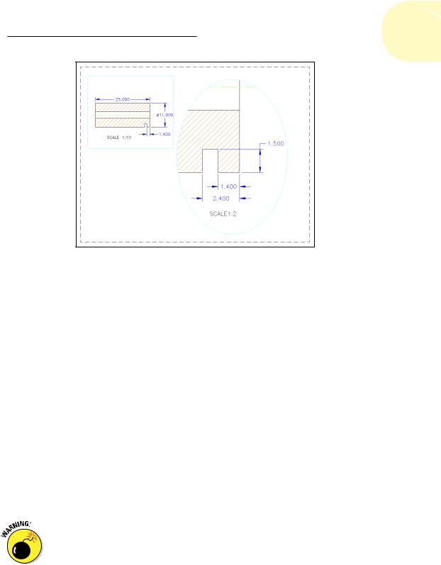
Here’s the easy way to create a multiscale drawing, such as the one in Figure 14-5.
1.Draw the object full-size in model space, including the small notch detail.
2.Select the 1:10 scale from the drop-down list under the Annotation Scale button in the lower-right corner of the AutoCAD window.
3.Apply the three dimensions that show in the Scale 1:10 view in Figure 14-5, using an annotative dimension style.
The figure shows paper space, but you’re working in model space.
www.it-ebooks.info
Chapter 14: Entering New Dimensions 317
Figure 14-5: A drawing with a detail at another scale.
4.Apply an annotative hatch, as we discuss in Chapter 15, and then draw the center line.
5.Edit the properties of the hatch pattern and the 1.400 dimension to add 1:2 scale factors, as we describe in Chapter 13.
6.Make sure that the Automatically Add Annotative Scales button is turned off, and change the Annotation Scale to 1:2.
Three existing dimensions disappear, and the hatch and the 1.400 dimension resize themselves.
7.Add the 1.500 and 2.400 dimensions.
8.Now comes the magic part. Switch to the paper space Layout 1 tab. Click the viewport boundary and then grip edit it approximately to the size and location shown.
Your model space drawing is probably not properly located, and the hatch and dimensions won’t show.
9.Click the viewport boundary again, and then click the Viewport Scale button (it probably reads something like 0.694694) and select 1:10 from the scale list.
The viewport zooms accordingly, and the hatch and 1:10 dimensions appear. If necessary, double-click in the viewport to enter model space and then pan accordingly.
Don’t zoom, or you lose the scale setting!
www.it-ebooks.info