

- •About the Authors
- •Dedication
- •Authors’ Acknowledgments
- •Table of Contents
- •Introduction
- •What’s Not (And What Is) in This Book
- •Mac attack!
- •Who Do We Think You Are?
- •How This Book Is Organized
- •Part I: AutoCAD 101
- •Part II: Let There Be Lines
- •Part III: If Drawings Could Talk
- •Part IV: Advancing with AutoCAD
- •Part V: On a 3D Spree
- •Part VI: The Part of Tens
- •But wait . . . there’s more!
- •Icons Used in This Book
- •A Few Conventions — Just in Case
- •Commanding from the keyboard
- •Tying things up with the Ribbon
- •Where to Go from Here
- •Why AutoCAD?
- •The Importance of Being DWG
- •Seeing the LT
- •Checking System Requirements
- •Suddenly, It’s 2013!
- •AutoCAD Does Windows (And Office)
- •And They’re Off: AutoCAD’s Opening Screens
- •Running with Ribbons
- •Getting with the Program
- •Looking for Mr. Status Bar
- •Let your fingers do the talking: The command window
- •The key(board) to AutoCAD success
- •Keeping tabs on palettes
- •Down the main stretch: The drawing area
- •Fun with F1
- •A Simple Setup
- •Drawing a (Base) Plate
- •Drawing rectangles on the right layers
- •Circling your plate
- •Nuts to you
- •Getting a Closer Look with Zoom and Pan
- •Modifying to Make It Merrier
- •Hip-hip-array!
- •Stretching out
- •Crossing your hatches
- •Following the Plot
- •A Setup Roadmap
- •Choosing your units
- •Weighing up your scales
- •Thinking annotatively
- •Thinking about paper
- •Defending your border
- •A Template for Success
- •Making the Most of Model Space
- •Setting your units
- •Making the drawing area snap-py (and grid-dy)
- •Setting linetype and dimension scales
- •Entering drawing properties
- •Making Templates Your Own
- •Setting Up a Layout in Paper Space
- •Will that be tabs or buttons?
- •View layouts Quick(View)ly
- •Creating a layout
- •Copying and changing layouts
- •Lost in paper space
- •Spaced out
- •A view(port) for drawing in
- •About Paper Space Layouts and Plotting
- •Managing Your Properties
- •Layer one on me!
- •Accumulating properties
- •Creating new layers
- •Manipulating layers
- •Using Named Objects
- •Using AutoCAD DesignCenter
- •Copying layers between drawings
- •Controlling Your Precision
- •Keyboard capers: Coordinate input
- •Understanding AutoCAD’s coordinate systems
- •Grab an object and make it snappy
- •Other Practical Precision Procedures
- •Introducing the AutoCAD Drawing Commands
- •The Straight and Narrow: Lines, Polylines, and Polygons
- •Toeing the line
- •Connecting the lines with polyline
- •Squaring off with rectangles
- •Choosing your sides with polygon
- •(Throwing) Curves
- •Going full circle
- •Arc-y-ology
- •Solar ellipses
- •Splines: The sketchy, sinuous curves
- •Donuts: The circles with a difference
- •Revision clouds on the horizon
- •Scoring Points
- •Commanding and Selecting
- •Command-first editing
- •Selection-first editing
- •Direct object manipulation
- •Choosing an editing style
- •Grab It
- •One-by-one selection
- •Selection boxes left and right
- •Perfecting Selecting
- •AutoCAD Groupies
- •Object Selection: Now You See It . . .
- •Get a Grip
- •About grips
- •A gripping example
- •Move it!
- •Copy, or a kinder, gentler Move
- •A warm-up stretch
- •Your AutoCAD Toolkit
- •The Big Three: Move, Copy, and Stretch
- •Base points and displacements
- •Move
- •Copy
- •Copy between drawings
- •Stretch
- •More Manipulations
- •Mirror
- •Rotate
- •Scale
- •Array
- •Offset
- •Slicing, Dicing, and Splicing
- •Trim and Extend
- •Break
- •Fillet and Chamfer and Blend
- •Join
- •When Editing Goes Bad
- •Zoom and Pan with Glass and Hand
- •The wheel deal
- •Navigating your drawing
- •Controlling your cube
- •Time to zoom
- •A View by Any Other Name . . .
- •Looking Around in Layout Land
- •Degenerating and Regenerating
- •Getting Ready to Write
- •Simply stylish text
- •Taking your text to new heights
- •One line or two?
- •Your text will be justified
- •Using the Same Old Line
- •Turning On Your Annotative Objects
- •Saying More in Multiline Text
- •Making it with Mtext
- •It slices; it dices . . .
- •Doing a number on your Mtext lists
- •Line up in columns — now!
- •Modifying Mtext
- •Gather Round the Tables
- •Tables have style, too
- •Creating and editing tables
- •Take Me to Your Leader
- •Electing a leader
- •Multi options for multileaders
- •How Do You Measure Up?
- •A Field Guide to Dimensions
- •The lazy drafter jumps over to the quick dimension commands
- •Dimension associativity
- •Where, oh where, do my dimensions go?
- •The Latest Styles in Dimensioning
- •Creating and managing dimension styles
- •Let’s get stylish!
- •Adjusting style settings
- •Size Matters
- •Details at other scales
- •Editing Dimensions
- •Editing dimension geometry
- •Editing dimension text
- •Controlling and editing dimension associativity
- •Batten Down the Hatches!
- •Don’t Count Your Hatches. . .
- •Size Matters!
- •We can do this the hard way. . .
- •. . . or we can do this the easy way
- •Annotative versus non-annotative
- •Pushing the Boundary (Of) Hatch
- •Your hatching has no style!
- •Hatch from scratch
- •Editing Hatch Objects
- •You Say Printing, We Say Plotting
- •The Plot Quickens
- •Plotting success in 16 steps
- •Get with the system
- •Configure it out
- •Preview one, two
- •Instead of fit, scale it
- •Plotting the Layout of the Land
- •Plotting Lineweights and Colors
- •Plotting with style
- •Plotting through thick and thin
- •Plotting in color
- •It’s a (Page) Setup!
- •Continuing the Plot Dialog
- •The Plot Sickens
- •Rocking with Blocks
- •Creating Block Definitions
- •Inserting Blocks
- •Attributes: Fill-in-the-Blank Blocks
- •Creating attribute definitions
- •Defining blocks that contain attribute definitions
- •Inserting blocks that contain attribute definitions
- •Edit attribute values
- •Extracting data
- •Exploding Blocks
- •Purging Unused Block Definitions
- •Arraying Associatively
- •Comparing the old and new ARRAY commands
- •Hip, hip, array!
- •Associatively editing
- •Going External
- •Becoming attached to your xrefs
- •Layer-palooza
- •Creating and editing an external reference file
- •Forging an xref path
- •Managing xrefs
- •Blocks, Xrefs, and Drawing Organization
- •Mastering the Raster
- •Attaching a raster image
- •Maintaining your image
- •Theme and Variations: Dynamic Blocks
- •Lights! Parameters!! Actions!!!
- •Manipulating dynamic blocks
- •Maintaining Design Intent
- •Defining terms
- •Forget about drawing with precision!
- •Constrain yourself
- •Understanding Geometric Constraints
- •Applying a little more constraint
- •AutoConstrain yourself!
- •Understanding Dimensional Constraints
- •Practice a little constraint
- •Making your drawing even smarter
- •Using the Parameters Manager
- •Dimensions or constraints — have it both ways!
- •The Internet and AutoCAD: An Overview
- •You send me
- •Send it with eTransmit
- •Rapid eTransmit
- •Bad reception?
- •Help from the Reference Manager
- •Design Web Format — Not Just for the Web
- •All about DWF and DWFx
- •Autodesk Design Review 2013
- •The Drawing Protection Racket
- •Autodesk Weather Forecast: Increasing Cloud
- •Working Solidly in the Cloud
- •Free AutoCAD!
- •Going once, going twice, going 123D
- •Your head planted firmly in the cloud
- •The pros
- •The cons
- •Cloudy with a shower of DWGs
- •AutoCAD 2013 cloud connectivity
- •Tomorrow’s Forecast
- •Understanding 3D Digital Models
- •Tools of the Trade
- •Warp speed ahead
- •Entering the third dimension
- •Untying the Ribbon and opening some palettes
- •Modeling from Above
- •Using 3D coordinate input
- •Using point filters
- •Object snaps and object snap tracking
- •Changing Planes
- •Displaying the UCS icon
- •Adjusting the UCS
- •Navigating the 3D Waters
- •Orbit à go-go
- •Taking a spin around the cube
- •Grabbing the SteeringWheels
- •Visualizing 3D Objects
- •Getting Your 3D Bearings
- •Creating a better 3D template
- •Seeing the world from new viewpoints
- •From Drawing to Modeling in 3D
- •Drawing basic 3D objects
- •Gaining a solid foundation
- •Drawing solid primitives
- •Adding the Third Dimension to 2D Objects
- •Creating 3D objects from 2D drawings
- •Modifying 3D Objects
- •Selecting subobjects
- •Working with gizmos
- •More 3D variants of 2D commands
- •Editing solids
- •Get the 2D Out of Here!
- •A different point of view
- •But wait! There’s more!
- •But wait! There’s less!
- •Do You See What I See?
- •Visualizing the Digital World
- •Adding Lighting
- •Default lighting
- •User-defined lights
- •Sunlight
- •Creating and Applying Materials
- •Defining a Background
- •Rendering a 3D Model
- •Autodesk Feedback Community
- •Autodesk Discussion Groups
- •Autodesk’s Own Bloggers
- •Autodesk University
- •The Autodesk Channel on YouTube
- •The World Wide (CAD) Web
- •Your Local ATC
- •Your Local User Group
- •AUGI
- •Books
- •Price
- •3D Abilities
- •Customization Options
- •Network Licensing
- •Express Tools
- •Parametrics
- •Standards Checking
- •Data Extraction
- •MLINE versus DLINE
- •Profiles
- •Reference Manager
- •And The Good News Is . . .
- •APERTURE
- •DIMASSOC
- •MENUBAR
- •MIRRTEXT
- •OSNAPZ
- •PICKBOX
- •REMEMBERFOLDERS
- •ROLLOVERTIPS
- •TOOLTIPS
- •VISRETAIN
- •And the Bonus Round
- •Index

Chapter 22: From Drawings to Models 493
Getting Your 3D Bearings
The first challenge in 3D modeling is being able to see your three-dimensional model on a two-dimensional computer screen. The normal model space view on the Model tab in the drawing area shows a single, projected 2D view of your model — the top-down, “plan” view by default.
AutoCAD provides two model space capabilities that enable you to escape this visual flatland:
With viewports, you can carve the model space drawing area into smaller rectangular areas, each of which shows a different view of the model.
With viewpoints, you can change the point in 3D space from which you look at the model. By setting a different viewpoint in each viewport, you can look at several sides of your model at the same time. It’s like looking at one of Picasso’s cubist paintings, only what you see is more orderly.
No matter how much or how little 3D modeling you’re thinking about doing, it’s well worth your while to set up a template. (We fill you in on drawing templates in Chapter 4.) If you’ve ever started a new drawing, you’re probably aware that AutoCAD already comes with a template for 3D modeling named acad3d.dwt (or acadiso3D.dwt for the metrically inclined). This is fine as far as it goes, but it only shows you a single view of your model. The next section explains how to improve on this template.
Creating a better 3D template
Model space viewports enable you to see several views of your model at one time, each from a different viewpoint. For this reason, model space viewports are especially useful when you’re creating and editing objects in 3D. As you draw and edit, the different views help ensure that you’re picking points that are located correctly in 3D space.
Chapter 5 discusses viewports in paper space, which are useful for creating layouts for use in plots and presentations in both 2D and 3D. Model space viewports, cousins of paper viewports, are less flexible but simpler, and are a great help in constructing 3D models.
Model space viewports divide the screen into separate rectangles with no gaps between them. Unlike paper space viewports, you can’t move, stretch, or overlap them. You can’t plot multiple model space viewports (that’s what paper space is for). And, unlike the situation in layouts, a layer that’s visible in one model space viewport always is visible in all of them.
www.it-ebooks.info
494 Part V: On a 3D Spree
You may hear or read references to tiled viewports, which is just another name for model space viewports. Tiled refers to the way in which model space viewports always fill the drawing area, with no gaps and no overlapping allowed. Conversely, paper space viewports are sometimes called floating viewports because you can move them around, leave gaps between them, and overlap them.
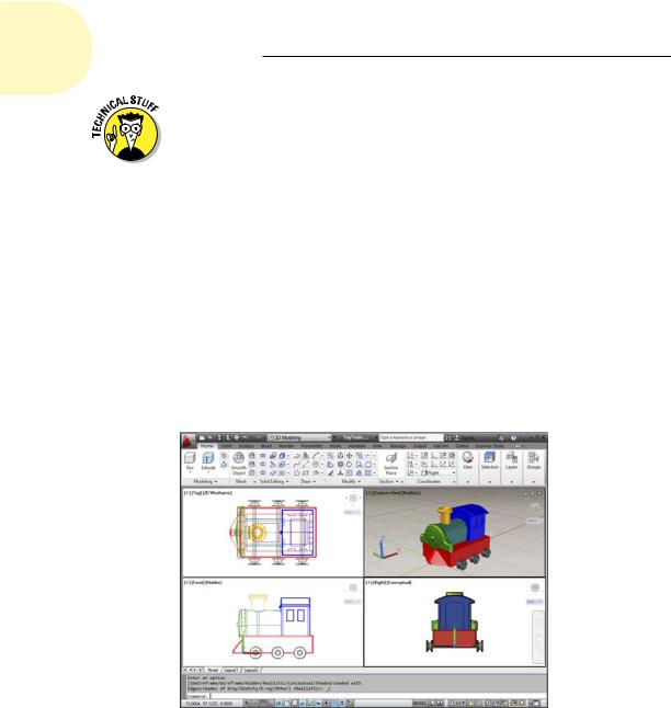
One of the best new features introduced in AutoCAD 2012 goes by the somewhat obscure title of in-canvas viewport controls. Those little text labels that you may have noticed at the top-left corner of the graphics area (see Figure 22-1, for example) are clickable controls that let you set the visual style and the view. What’s especially nifty is that double-clicking the plus or minus sign toggles the drawing area between multiple tiled viewports already configured for 3D viewing, and a single, maximized viewport. Out of
the box, double-clicking the minus (–) sign switches to four equal-sized viewports showing different views of the geometry. Figure 22-1 illustrates what we’re talking about: In this example, you see four viewports, four different viewpoints, and four different visual styles. That’s a bit extreme for everyday work, but it gives you an idea of the possibilities.
Figure 22-1: 3D viewing from every which way.
We highly recommend working with multiple viewports when you’re modeling in 3D — that way you get to see exactly what you’re doing in all three dimensions, in real time. Our preference is to work mostly in the isometric viewport, so we make that one larger than the other three. The in-canvas
www.it-ebooks.info

Chapter 22: From Drawings to Models 495
viewport toggle will switch back and forth between the last multiple viewport you set up, and a maximized viewport. In the following steps, we explain how to set up the tiled-viewport configuration you see in Figure 22-3.
1.If you’re not already in the 3D Modeling workspace, click the Workspace drop-down list on the Quick Access Toolbar and choose 3D Modeling.
You can also click the Workspace Switching button on the status bar and again, select 3D Modeling. If the Materials Browser palette opens, close it.
2.Click New on the Quick Access Toolbar to open the Select Template dialog box.
If a new blank drawing appears and you don’t see the Select Template dialog box, someone has assigned a default template to this button in the Options dialog box. In that case, click the Application button (the Big Red A) and choose New, and then choose Drawing from the submenu.
3.Choose acad.dwt (choose acadiso.dwt if metric is your preference), and click Open.
Yes, we know there are ready-made 3D templates (acad3d.dwt and acadiso3d.dwt), but trust us — it’s easier to start this setup from a 2D template.
4.From the Viewports panel on the Ribbon’s View tab, choose Named.
The Viewports dialog box appears.
5.Click the New Viewports tab to make it current; then choose Four: Left (our preference) or Four: Right from the Standard Viewports list box.
The Preview panel shows a large, squarish viewport occupying most of the work area, with three small squarish viewports stacked on the left (or right). The default 2D setup shows the visual style of all four viewports as “2D Wireframe.” (We explain visual styles in Chapter 21.)
6.From the Setup drop-down list, choose 3D.
The visual styles remain as 2D Wireframe, but the view direction (listed as “Current” in 2D Setup) is now SE Isometric in the large viewport, while the three small viewports show Top, Front, and Right orthographic views.
When modeling in 3D, it’s nearly always helpful to look at your objects in different ways at the same time. When looking at orthographic views, same as with a drafted drawing, you probably want to see all your linework. But you can get a better sense of the three dimensionality of your model by looking at it in a shaded view. With multiple viewports, you can do both at the same time.
www.it-ebooks.info
496 Part V: On a 3D Spree
7.In the Preview area, click inside the large SE Isometric viewport and then choose Conceptual from the Visual Style drop-down list.
You’re almost finished in here. Rather than go through this setup every time you want to do some modeling, give your new viewport configuration a name.
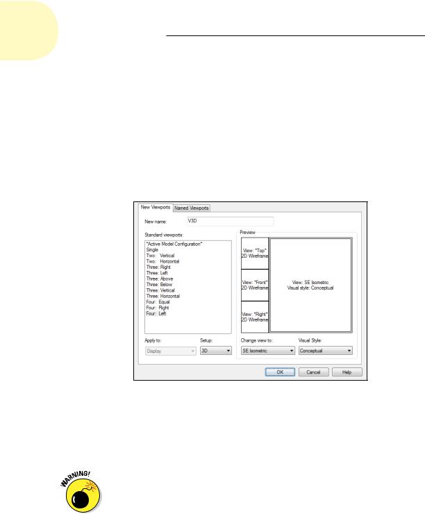
8.In the New Name box at the top of the Viewports dialog box, enter a name — V3D, for example — for the configuration.
Figure 22-2 shows the new, named viewport configuration. After you close the Viewports dialog box, you can restore this configuration at any time by clicking the Named Viewports tab, choosing V3D, and clicking OK.
Figure 22-2: Setting up a 3D work environment in the Viewports dialog box.
9.Click OK to save the viewport configuration and close the Viewports dialog box.
In Figure 22-3, we turned off the grid in the three small ortho viewports, but whether you leave it on or turn it off is a matter of personal preference.
The ViewCube’s Home button can trip you up by changing to a view you don’t expect. (We introduce the ViewCube in Chapter 21.) If you want to keep the current SE Isometric viewpoint, be sure to reset the Home view. To do this, simply right-click anywhere in the ViewCube and choose Set Current View as Home from the menu that appears. And because you’ve gone to the trouble of setting up a shaded 3D viewport, why not make it a little more realistic and turn on perspective mode at the same time?
www.it-ebooks.info
Chapter 22: From Drawings to Models 497
Figure 22-3: 2D and 3D all at the same time.
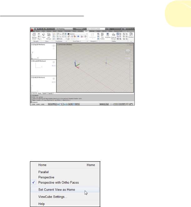
10.In the large 3D viewport, right-click the ViewCube to display its shortcut menu and then choose Perspective With Ortho Faces (see Figure 22-4).
Selecting Perspective shows your orthographic views in perspective mode, and usually you don’t want that. Selecting Perspective with Ortho Faces resets the projection mode from perspective to parallel when you switch to an orthographic view.
Figure 22-4: Changing settings in the ViewCube’s right-click menu.
11.Repeat Step 10, this time selecting Set Current View as Home.
Now you can readily return to this viewport configuration, keeping the same viewpoint in all viewports, perspective projection in the 3D viewport, and parallel projection in the orthographic viewports.
www.it-ebooks.info