

- •About the Authors
- •Dedication
- •Authors’ Acknowledgments
- •Table of Contents
- •Introduction
- •What’s Not (And What Is) in This Book
- •Mac attack!
- •Who Do We Think You Are?
- •How This Book Is Organized
- •Part I: AutoCAD 101
- •Part II: Let There Be Lines
- •Part III: If Drawings Could Talk
- •Part IV: Advancing with AutoCAD
- •Part V: On a 3D Spree
- •Part VI: The Part of Tens
- •But wait . . . there’s more!
- •Icons Used in This Book
- •A Few Conventions — Just in Case
- •Commanding from the keyboard
- •Tying things up with the Ribbon
- •Where to Go from Here
- •Why AutoCAD?
- •The Importance of Being DWG
- •Seeing the LT
- •Checking System Requirements
- •Suddenly, It’s 2013!
- •AutoCAD Does Windows (And Office)
- •And They’re Off: AutoCAD’s Opening Screens
- •Running with Ribbons
- •Getting with the Program
- •Looking for Mr. Status Bar
- •Let your fingers do the talking: The command window
- •The key(board) to AutoCAD success
- •Keeping tabs on palettes
- •Down the main stretch: The drawing area
- •Fun with F1
- •A Simple Setup
- •Drawing a (Base) Plate
- •Drawing rectangles on the right layers
- •Circling your plate
- •Nuts to you
- •Getting a Closer Look with Zoom and Pan
- •Modifying to Make It Merrier
- •Hip-hip-array!
- •Stretching out
- •Crossing your hatches
- •Following the Plot
- •A Setup Roadmap
- •Choosing your units
- •Weighing up your scales
- •Thinking annotatively
- •Thinking about paper
- •Defending your border
- •A Template for Success
- •Making the Most of Model Space
- •Setting your units
- •Making the drawing area snap-py (and grid-dy)
- •Setting linetype and dimension scales
- •Entering drawing properties
- •Making Templates Your Own
- •Setting Up a Layout in Paper Space
- •Will that be tabs or buttons?
- •View layouts Quick(View)ly
- •Creating a layout
- •Copying and changing layouts
- •Lost in paper space
- •Spaced out
- •A view(port) for drawing in
- •About Paper Space Layouts and Plotting
- •Managing Your Properties
- •Layer one on me!
- •Accumulating properties
- •Creating new layers
- •Manipulating layers
- •Using Named Objects
- •Using AutoCAD DesignCenter
- •Copying layers between drawings
- •Controlling Your Precision
- •Keyboard capers: Coordinate input
- •Understanding AutoCAD’s coordinate systems
- •Grab an object and make it snappy
- •Other Practical Precision Procedures
- •Introducing the AutoCAD Drawing Commands
- •The Straight and Narrow: Lines, Polylines, and Polygons
- •Toeing the line
- •Connecting the lines with polyline
- •Squaring off with rectangles
- •Choosing your sides with polygon
- •(Throwing) Curves
- •Going full circle
- •Arc-y-ology
- •Solar ellipses
- •Splines: The sketchy, sinuous curves
- •Donuts: The circles with a difference
- •Revision clouds on the horizon
- •Scoring Points
- •Commanding and Selecting
- •Command-first editing
- •Selection-first editing
- •Direct object manipulation
- •Choosing an editing style
- •Grab It
- •One-by-one selection
- •Selection boxes left and right
- •Perfecting Selecting
- •AutoCAD Groupies
- •Object Selection: Now You See It . . .
- •Get a Grip
- •About grips
- •A gripping example
- •Move it!
- •Copy, or a kinder, gentler Move
- •A warm-up stretch
- •Your AutoCAD Toolkit
- •The Big Three: Move, Copy, and Stretch
- •Base points and displacements
- •Move
- •Copy
- •Copy between drawings
- •Stretch
- •More Manipulations
- •Mirror
- •Rotate
- •Scale
- •Array
- •Offset
- •Slicing, Dicing, and Splicing
- •Trim and Extend
- •Break
- •Fillet and Chamfer and Blend
- •Join
- •When Editing Goes Bad
- •Zoom and Pan with Glass and Hand
- •The wheel deal
- •Navigating your drawing
- •Controlling your cube
- •Time to zoom
- •A View by Any Other Name . . .
- •Looking Around in Layout Land
- •Degenerating and Regenerating
- •Getting Ready to Write
- •Simply stylish text
- •Taking your text to new heights
- •One line or two?
- •Your text will be justified
- •Using the Same Old Line
- •Turning On Your Annotative Objects
- •Saying More in Multiline Text
- •Making it with Mtext
- •It slices; it dices . . .
- •Doing a number on your Mtext lists
- •Line up in columns — now!
- •Modifying Mtext
- •Gather Round the Tables
- •Tables have style, too
- •Creating and editing tables
- •Take Me to Your Leader
- •Electing a leader
- •Multi options for multileaders
- •How Do You Measure Up?
- •A Field Guide to Dimensions
- •The lazy drafter jumps over to the quick dimension commands
- •Dimension associativity
- •Where, oh where, do my dimensions go?
- •The Latest Styles in Dimensioning
- •Creating and managing dimension styles
- •Let’s get stylish!
- •Adjusting style settings
- •Size Matters
- •Details at other scales
- •Editing Dimensions
- •Editing dimension geometry
- •Editing dimension text
- •Controlling and editing dimension associativity
- •Batten Down the Hatches!
- •Don’t Count Your Hatches. . .
- •Size Matters!
- •We can do this the hard way. . .
- •. . . or we can do this the easy way
- •Annotative versus non-annotative
- •Pushing the Boundary (Of) Hatch
- •Your hatching has no style!
- •Hatch from scratch
- •Editing Hatch Objects
- •You Say Printing, We Say Plotting
- •The Plot Quickens
- •Plotting success in 16 steps
- •Get with the system
- •Configure it out
- •Preview one, two
- •Instead of fit, scale it
- •Plotting the Layout of the Land
- •Plotting Lineweights and Colors
- •Plotting with style
- •Plotting through thick and thin
- •Plotting in color
- •It’s a (Page) Setup!
- •Continuing the Plot Dialog
- •The Plot Sickens
- •Rocking with Blocks
- •Creating Block Definitions
- •Inserting Blocks
- •Attributes: Fill-in-the-Blank Blocks
- •Creating attribute definitions
- •Defining blocks that contain attribute definitions
- •Inserting blocks that contain attribute definitions
- •Edit attribute values
- •Extracting data
- •Exploding Blocks
- •Purging Unused Block Definitions
- •Arraying Associatively
- •Comparing the old and new ARRAY commands
- •Hip, hip, array!
- •Associatively editing
- •Going External
- •Becoming attached to your xrefs
- •Layer-palooza
- •Creating and editing an external reference file
- •Forging an xref path
- •Managing xrefs
- •Blocks, Xrefs, and Drawing Organization
- •Mastering the Raster
- •Attaching a raster image
- •Maintaining your image
- •Theme and Variations: Dynamic Blocks
- •Lights! Parameters!! Actions!!!
- •Manipulating dynamic blocks
- •Maintaining Design Intent
- •Defining terms
- •Forget about drawing with precision!
- •Constrain yourself
- •Understanding Geometric Constraints
- •Applying a little more constraint
- •AutoConstrain yourself!
- •Understanding Dimensional Constraints
- •Practice a little constraint
- •Making your drawing even smarter
- •Using the Parameters Manager
- •Dimensions or constraints — have it both ways!
- •The Internet and AutoCAD: An Overview
- •You send me
- •Send it with eTransmit
- •Rapid eTransmit
- •Bad reception?
- •Help from the Reference Manager
- •Design Web Format — Not Just for the Web
- •All about DWF and DWFx
- •Autodesk Design Review 2013
- •The Drawing Protection Racket
- •Autodesk Weather Forecast: Increasing Cloud
- •Working Solidly in the Cloud
- •Free AutoCAD!
- •Going once, going twice, going 123D
- •Your head planted firmly in the cloud
- •The pros
- •The cons
- •Cloudy with a shower of DWGs
- •AutoCAD 2013 cloud connectivity
- •Tomorrow’s Forecast
- •Understanding 3D Digital Models
- •Tools of the Trade
- •Warp speed ahead
- •Entering the third dimension
- •Untying the Ribbon and opening some palettes
- •Modeling from Above
- •Using 3D coordinate input
- •Using point filters
- •Object snaps and object snap tracking
- •Changing Planes
- •Displaying the UCS icon
- •Adjusting the UCS
- •Navigating the 3D Waters
- •Orbit à go-go
- •Taking a spin around the cube
- •Grabbing the SteeringWheels
- •Visualizing 3D Objects
- •Getting Your 3D Bearings
- •Creating a better 3D template
- •Seeing the world from new viewpoints
- •From Drawing to Modeling in 3D
- •Drawing basic 3D objects
- •Gaining a solid foundation
- •Drawing solid primitives
- •Adding the Third Dimension to 2D Objects
- •Creating 3D objects from 2D drawings
- •Modifying 3D Objects
- •Selecting subobjects
- •Working with gizmos
- •More 3D variants of 2D commands
- •Editing solids
- •Get the 2D Out of Here!
- •A different point of view
- •But wait! There’s more!
- •But wait! There’s less!
- •Do You See What I See?
- •Visualizing the Digital World
- •Adding Lighting
- •Default lighting
- •User-defined lights
- •Sunlight
- •Creating and Applying Materials
- •Defining a Background
- •Rendering a 3D Model
- •Autodesk Feedback Community
- •Autodesk Discussion Groups
- •Autodesk’s Own Bloggers
- •Autodesk University
- •The Autodesk Channel on YouTube
- •The World Wide (CAD) Web
- •Your Local ATC
- •Your Local User Group
- •AUGI
- •Books
- •Price
- •3D Abilities
- •Customization Options
- •Network Licensing
- •Express Tools
- •Parametrics
- •Standards Checking
- •Data Extraction
- •MLINE versus DLINE
- •Profiles
- •Reference Manager
- •And The Good News Is . . .
- •APERTURE
- •DIMASSOC
- •MENUBAR
- •MIRRTEXT
- •OSNAPZ
- •PICKBOX
- •REMEMBERFOLDERS
- •ROLLOVERTIPS
- •TOOLTIPS
- •VISRETAIN
- •And the Bonus Round
- •Index
Chapter 13: Text with Character 279
Saying More in Multiline Text
When you just can’t shoehorn your creative genius into one or more one-line pieces of text, AutoCAD’s multiline text object gives you room to go on and on and on. The following procedure shows you how to create multiline text with the MTEXT command.
Making it with Mtext
The first part of the MTEXT command prompts you for various points and options. Read these steps and the prompts carefully to avoid confusion.
Here’s how you use the MTEXT command:
1.Set an appropriate text style current and (optionally) turn off running object snaps, as described in Steps 1 and 2 in the “Using the Same Old Line” section, earlier in this chapter.
If you’re doing real drafting, you should also set an appropriate layer to be current.
2.On the Home tab’s Annotation panel, click the upper part of the split button labeled Text to start the MTEXT command.
The command line displays the current text style and height settings, and prompts you to select the first corner of an imaginary rectangle that will determine the word-wrapping width for the text object:
Current text style: “Standard” Text height: 0.2000
Annotative: No
Specify first corner:
3. Pick a point in the drawing.
The command line prompts you for the opposite corner of a rectangle that will determine the word-wrapping width; it also gives you the option of changing settings first:
Specify opposite corner or [Height/Justify/Line spacing/Rotation/Style/Width/Columns]:
4. Type H and press Enter to change the default text height.
The command line prompts you for a new default text height if your current text style has a height of 0.0:
Specify height <0.2000>:
5.If applicable, type an appropriate text height.
See the “Taking your text to new heights” section, earlier in this chapter, for information. If you’re adding text in model space, we highly recommend that you use annotative text.
www.it-ebooks.info
280 Part III: If Drawings Could Talk
The prompt for the opposite corner of the Mtext rectangle reappears.
The command line shows
Specify opposite corner or [Height/Justify/Line spacing/Rotation/Style/Width/Columns]:
6.If you want a different justification from the default (top left), type J, press Enter, and choose one of the other justification options.
Enter justify multiline text in the search box of the online help system if you want an explanation of the other justification options.
7.Pick another point in the drawing.
Don’t worry about the height of the rectangle that you create by choosing the second point; the width of the rectangle is all that matters. AutoCAD adjusts the height of the text rectangle to accommodate the number of lines of word-wrapped text. Don’t worry too much about the width, either; you can adjust it later.
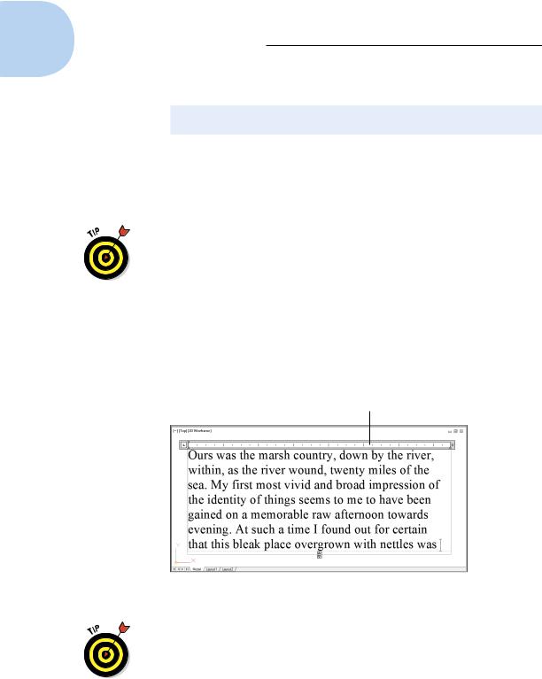
The In-Place Text Editor frameless window appears with the tab and indent ruler above it, and a previously hidden Text Editor contextual tab appears on the Ribbon, as shown in Figure 13-4. (If you don’t see the tab and indent ruler at the top of your Text Editor window, right-click inside the window and choose Editor Settings, and then Show Ruler from the right-click menu.)
Tab and indent ruler
Figure 13-4: Adding immortal multiline text.
New isn’t always better; you may prefer the classic Text Formatting toolbar over the Ribbon’s Text Editor contextual tab. If you want to give the classic version a test-drive, change the value of the system variable MTEXTTOOLBAR. The default value (2) displays the Text Editor tab only; setting it to 1 displays both the tab and the toolbar. We don’t recommend
www.it-ebooks.info
Chapter 13: Text with Character 281
setting this variable to 0 — that turns off the Text Formatting toolbar in all workspaces. For more about system variables, see Chapter 26.
When you create multiline text in either AutoCAD or AutoCAD LT, your text objects default to Dynamic Column mode. You can tell that’s what you’re going to get if the In-Place Text Editor displays a double-headed- arrow symbol in the center of the bottom border of the rectangle you define (refer to Figure 13-4). As indicated earlier, the initial selection window primarily sets the width. By default, if you enter enough text so that it fills the window, MTEXT defaults to splitting the text into two columns like a newspaper. If you don’t like this, you can dynamically stretch the text window to be wider or longer.
If you never want to use columns in the current drawing, click Columns on the Insert panel of the Text Editor tab, which only appears when you’re editing text. This sets the MTEXTCOLUMN system variable to 0. It affects only the current drawing, so if you never want columns, set this up in your template drawings. We cover templates in Chapter 4.
8.Verify the text font and height.
The text font and height should be right if you correctly performed Steps 1, 4, and 5. If not, you can change these settings in the Font dropdown list and the Text Height text box on the Text Editor tab (or the classic Text Formatting toolbar).
9.Type text into the text area of the In-Place Text Editor.
AutoCAD word-wraps multiline text automatically. If you want to force a line break at a particular location, press Enter.
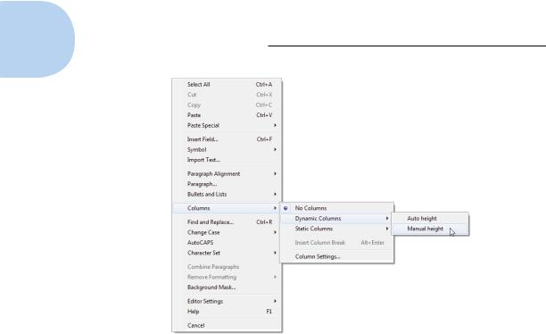
10.If you want other formatting options, select text, right-click, and make an appropriate choice from the menu (as shown in Figure 13-5).
By convention in most industries, text in drawings is always uppercase. How many times have you forgotten to press the Caps Lock key before entering drawing text? How many times have you forgotten to turn Caps Lock off again when it’s time to type your e-mail? To save yourself some agony, right-click in the In-Place Text Editor and choose AutoCAPS from the menu.
11. Click Close Text Editor (or OK in the classic Text Formatting toolbar).
The In-Place Text Editor window closes, and AutoCAD adds your text to the drawing.
You can close the text editor much more easily by simply clicking outside its window. But if you like clicking buttons instead, AutoCAD has amply provided for you.
www.it-ebooks.info
282 Part III: If Drawings Could Talk
Figure 13-5: Right-click your way to textual excellence.
12.Use annotation scales with multiline text objects.
The steps are the same for multiline text as for single-line text. Refer to the “Turning On Your Annotative Objects” section, earlier in this chapter, if you need a refresher.
As you can tell by looking at the Text Editor tab (or the Text Formatting toolbar) and multiline text right-click menu, the MTEXT command gives you plenty of other options. You can show or hide the toolbar, the ruler, or the Options buttons, and you can give the In-Place Text Editor an opaque background. Other tool buttons give you access to columns and numbered or bulleted lists (both are covered in the section “Doing a number on your Mtext lists,” later in this chapter).
Between them, the Text Editor tab (or the Text Formatting toolbar) and the right-click menu also include a Stack/Unstack feature for fractions, a Find and Replace utility, tools for changing between lowercase and uppercase, options for applying background masks and inserting fields, a special Symbol submenu, and an Import Text option for importing text from a TXT (ASCII text) file or RTF (Rich Text Format) file. We discuss background masks and fields in the next section. If you think you may have a use for any of these other features, choose Command Reference Commands M Commands MTEXT in AutoCAD’s online help browser to find out more about them.
www.it-ebooks.info