

Chapter 4: Setup for Success 103
Selecting the Display Grid Beyond Limits check box allows the grid to display over the entire drawing area, no matter how far you’re zoomed out. Clearing this check box makes AutoCAD behave the way it’s always behaved — that is, the grid is displayed only in the area defined by the drawing limits.
The Follow Dynamic UCS option (not available in AutoCAD LT) is a 3D-specific feature that changes your drawing plane as you mouse over 3D objects. We cover this feature in Chapter 22.
7. Click OK to close the Drafting Settings dialog box.
Setting linetype and dimension scales
Even though you’ve engraved the drawing scale factor on your desk and written it on your hand — not vice versa — AutoCAD doesn’t know the drawing scale until you enter it. Keeping AutoCAD in the dark is fine as long as you’re just drawing continuous lines and curves representing real-world geometry because you draw these objects at their real-world size, without worrying about plot scale.
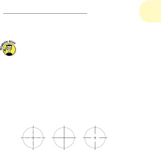
However . . . as soon as you start using noncontinuous dash-dot linetypes (line patterns that contain gaps in them), you need to tell AutoCAD how to scale the gaps in the linetypes based on the plot scale. If you forget this, the dash-dot linetype patterns can look waaaay too big or too small. Figure 4-6 shows what we mean.
Too Small... |
Too Big... |
Just Right! |
Figure 4-6: . . . and this little center line looks juuuust right!
The scale factor that controls dash-dot linetypes is found in a system variable called LTSCALE (as in LineType SCALE). You can change this setting at any time, but it’s best to set it correctly when you’re setting up the drawing.
The following sequence includes directions for typing system variable and command names. To set the linetype scale at the keyboard, follow these steps:
www.it-ebooks.info
104 Part I: AutoCAD 101
1. Type LTSCALE (or LTS) and press Enter.
AutoCAD responds with a prompt, asking you for the scale factor. The value at the end of the prompt is the current linetype scale setting, as shown in the following command line example:
Enter new linetype scale factor <1.0000>:
2.Type the value you want for the linetype scale and press Enter.
The easiest choice is to set the linetype scale to the drawing scale factor. Some people, however, find that the dashes and gaps in dashdot linetypes get a bit too long when they use the drawing scale factor. If you’re one of those people, set LTSCALE to one-half of the drawing scale factor. (Feel free to experiment with this value; some people prefer a linetype scale of three-quarters the scale factor. If you’re working in metric, try 0.75 times the scale factor instead — just ask your calculator if you don’t believe me.)
Alternatively, you can specify linetype scale in the Linetype Manager dialog box: Click the Linetype drop-down on the Properties panel of the Ribbon’s Home tab and select Other. Then in the Linetype Manager
dialog box, click the Show Details button, and type your desired linetype scale in the Global Scale Factor text box.
Besides LTSCALE, there are three other similarly named system variables you can use to control the display of dash-dot linetypes:
PSLTSCALE: Makes linetype spacing look the same in paper space viewports, regardless of the viewport scale.
CELTSCALE: Changes the effective linetype scale factor for new objects.
MSLTSCALE: Visually displays dash-dot linetypes in the model tab based on the annotative scale setting.
If any of these sound useful — and we highly recommend you enable PSLTSCALE — check them out in the online help index.
The procedure described here for setting linetype scale assumes that you’re starting a new drawing from one of the plain-jane templates (acad.dwt
or acadiso.dwt in the full version, acadlt.dwt or acadltiso.dwt in AutoCAD LT) and using the default linetype scale. Don’t change LTSCALE in existing drawings without knowing exactly why you’re doing it and what values to set them to, in case someone before you set their values for good reasons.
Entering drawing properties
We recommend one last bit of housekeeping before you’re finished with model space drawing setup: Enter summary information in the Drawing Properties dialog box, as shown in Figure 4-7. Click the Application button; in
www.it-ebooks.info