

- •About the Authors
- •Dedication
- •Authors’ Acknowledgments
- •Table of Contents
- •Introduction
- •What’s Not (And What Is) in This Book
- •Mac attack!
- •Who Do We Think You Are?
- •How This Book Is Organized
- •Part I: AutoCAD 101
- •Part II: Let There Be Lines
- •Part III: If Drawings Could Talk
- •Part IV: Advancing with AutoCAD
- •Part V: On a 3D Spree
- •Part VI: The Part of Tens
- •But wait . . . there’s more!
- •Icons Used in This Book
- •A Few Conventions — Just in Case
- •Commanding from the keyboard
- •Tying things up with the Ribbon
- •Where to Go from Here
- •Why AutoCAD?
- •The Importance of Being DWG
- •Seeing the LT
- •Checking System Requirements
- •Suddenly, It’s 2013!
- •AutoCAD Does Windows (And Office)
- •And They’re Off: AutoCAD’s Opening Screens
- •Running with Ribbons
- •Getting with the Program
- •Looking for Mr. Status Bar
- •Let your fingers do the talking: The command window
- •The key(board) to AutoCAD success
- •Keeping tabs on palettes
- •Down the main stretch: The drawing area
- •Fun with F1
- •A Simple Setup
- •Drawing a (Base) Plate
- •Drawing rectangles on the right layers
- •Circling your plate
- •Nuts to you
- •Getting a Closer Look with Zoom and Pan
- •Modifying to Make It Merrier
- •Hip-hip-array!
- •Stretching out
- •Crossing your hatches
- •Following the Plot
- •A Setup Roadmap
- •Choosing your units
- •Weighing up your scales
- •Thinking annotatively
- •Thinking about paper
- •Defending your border
- •A Template for Success
- •Making the Most of Model Space
- •Setting your units
- •Making the drawing area snap-py (and grid-dy)
- •Setting linetype and dimension scales
- •Entering drawing properties
- •Making Templates Your Own
- •Setting Up a Layout in Paper Space
- •Will that be tabs or buttons?
- •View layouts Quick(View)ly
- •Creating a layout
- •Copying and changing layouts
- •Lost in paper space
- •Spaced out
- •A view(port) for drawing in
- •About Paper Space Layouts and Plotting
- •Managing Your Properties
- •Layer one on me!
- •Accumulating properties
- •Creating new layers
- •Manipulating layers
- •Using Named Objects
- •Using AutoCAD DesignCenter
- •Copying layers between drawings
- •Controlling Your Precision
- •Keyboard capers: Coordinate input
- •Understanding AutoCAD’s coordinate systems
- •Grab an object and make it snappy
- •Other Practical Precision Procedures
- •Introducing the AutoCAD Drawing Commands
- •The Straight and Narrow: Lines, Polylines, and Polygons
- •Toeing the line
- •Connecting the lines with polyline
- •Squaring off with rectangles
- •Choosing your sides with polygon
- •(Throwing) Curves
- •Going full circle
- •Arc-y-ology
- •Solar ellipses
- •Splines: The sketchy, sinuous curves
- •Donuts: The circles with a difference
- •Revision clouds on the horizon
- •Scoring Points
- •Commanding and Selecting
- •Command-first editing
- •Selection-first editing
- •Direct object manipulation
- •Choosing an editing style
- •Grab It
- •One-by-one selection
- •Selection boxes left and right
- •Perfecting Selecting
- •AutoCAD Groupies
- •Object Selection: Now You See It . . .
- •Get a Grip
- •About grips
- •A gripping example
- •Move it!
- •Copy, or a kinder, gentler Move
- •A warm-up stretch
- •Your AutoCAD Toolkit
- •The Big Three: Move, Copy, and Stretch
- •Base points and displacements
- •Move
- •Copy
- •Copy between drawings
- •Stretch
- •More Manipulations
- •Mirror
- •Rotate
- •Scale
- •Array
- •Offset
- •Slicing, Dicing, and Splicing
- •Trim and Extend
- •Break
- •Fillet and Chamfer and Blend
- •Join
- •When Editing Goes Bad
- •Zoom and Pan with Glass and Hand
- •The wheel deal
- •Navigating your drawing
- •Controlling your cube
- •Time to zoom
- •A View by Any Other Name . . .
- •Looking Around in Layout Land
- •Degenerating and Regenerating
- •Getting Ready to Write
- •Simply stylish text
- •Taking your text to new heights
- •One line or two?
- •Your text will be justified
- •Using the Same Old Line
- •Turning On Your Annotative Objects
- •Saying More in Multiline Text
- •Making it with Mtext
- •It slices; it dices . . .
- •Doing a number on your Mtext lists
- •Line up in columns — now!
- •Modifying Mtext
- •Gather Round the Tables
- •Tables have style, too
- •Creating and editing tables
- •Take Me to Your Leader
- •Electing a leader
- •Multi options for multileaders
- •How Do You Measure Up?
- •A Field Guide to Dimensions
- •The lazy drafter jumps over to the quick dimension commands
- •Dimension associativity
- •Where, oh where, do my dimensions go?
- •The Latest Styles in Dimensioning
- •Creating and managing dimension styles
- •Let’s get stylish!
- •Adjusting style settings
- •Size Matters
- •Details at other scales
- •Editing Dimensions
- •Editing dimension geometry
- •Editing dimension text
- •Controlling and editing dimension associativity
- •Batten Down the Hatches!
- •Don’t Count Your Hatches. . .
- •Size Matters!
- •We can do this the hard way. . .
- •. . . or we can do this the easy way
- •Annotative versus non-annotative
- •Pushing the Boundary (Of) Hatch
- •Your hatching has no style!
- •Hatch from scratch
- •Editing Hatch Objects
- •You Say Printing, We Say Plotting
- •The Plot Quickens
- •Plotting success in 16 steps
- •Get with the system
- •Configure it out
- •Preview one, two
- •Instead of fit, scale it
- •Plotting the Layout of the Land
- •Plotting Lineweights and Colors
- •Plotting with style
- •Plotting through thick and thin
- •Plotting in color
- •It’s a (Page) Setup!
- •Continuing the Plot Dialog
- •The Plot Sickens
- •Rocking with Blocks
- •Creating Block Definitions
- •Inserting Blocks
- •Attributes: Fill-in-the-Blank Blocks
- •Creating attribute definitions
- •Defining blocks that contain attribute definitions
- •Inserting blocks that contain attribute definitions
- •Edit attribute values
- •Extracting data
- •Exploding Blocks
- •Purging Unused Block Definitions
- •Arraying Associatively
- •Comparing the old and new ARRAY commands
- •Hip, hip, array!
- •Associatively editing
- •Going External
- •Becoming attached to your xrefs
- •Layer-palooza
- •Creating and editing an external reference file
- •Forging an xref path
- •Managing xrefs
- •Blocks, Xrefs, and Drawing Organization
- •Mastering the Raster
- •Attaching a raster image
- •Maintaining your image
- •Theme and Variations: Dynamic Blocks
- •Lights! Parameters!! Actions!!!
- •Manipulating dynamic blocks
- •Maintaining Design Intent
- •Defining terms
- •Forget about drawing with precision!
- •Constrain yourself
- •Understanding Geometric Constraints
- •Applying a little more constraint
- •AutoConstrain yourself!
- •Understanding Dimensional Constraints
- •Practice a little constraint
- •Making your drawing even smarter
- •Using the Parameters Manager
- •Dimensions or constraints — have it both ways!
- •The Internet and AutoCAD: An Overview
- •You send me
- •Send it with eTransmit
- •Rapid eTransmit
- •Bad reception?
- •Help from the Reference Manager
- •Design Web Format — Not Just for the Web
- •All about DWF and DWFx
- •Autodesk Design Review 2013
- •The Drawing Protection Racket
- •Autodesk Weather Forecast: Increasing Cloud
- •Working Solidly in the Cloud
- •Free AutoCAD!
- •Going once, going twice, going 123D
- •Your head planted firmly in the cloud
- •The pros
- •The cons
- •Cloudy with a shower of DWGs
- •AutoCAD 2013 cloud connectivity
- •Tomorrow’s Forecast
- •Understanding 3D Digital Models
- •Tools of the Trade
- •Warp speed ahead
- •Entering the third dimension
- •Untying the Ribbon and opening some palettes
- •Modeling from Above
- •Using 3D coordinate input
- •Using point filters
- •Object snaps and object snap tracking
- •Changing Planes
- •Displaying the UCS icon
- •Adjusting the UCS
- •Navigating the 3D Waters
- •Orbit à go-go
- •Taking a spin around the cube
- •Grabbing the SteeringWheels
- •Visualizing 3D Objects
- •Getting Your 3D Bearings
- •Creating a better 3D template
- •Seeing the world from new viewpoints
- •From Drawing to Modeling in 3D
- •Drawing basic 3D objects
- •Gaining a solid foundation
- •Drawing solid primitives
- •Adding the Third Dimension to 2D Objects
- •Creating 3D objects from 2D drawings
- •Modifying 3D Objects
- •Selecting subobjects
- •Working with gizmos
- •More 3D variants of 2D commands
- •Editing solids
- •Get the 2D Out of Here!
- •A different point of view
- •But wait! There’s more!
- •But wait! There’s less!
- •Do You See What I See?
- •Visualizing the Digital World
- •Adding Lighting
- •Default lighting
- •User-defined lights
- •Sunlight
- •Creating and Applying Materials
- •Defining a Background
- •Rendering a 3D Model
- •Autodesk Feedback Community
- •Autodesk Discussion Groups
- •Autodesk’s Own Bloggers
- •Autodesk University
- •The Autodesk Channel on YouTube
- •The World Wide (CAD) Web
- •Your Local ATC
- •Your Local User Group
- •AUGI
- •Books
- •Price
- •3D Abilities
- •Customization Options
- •Network Licensing
- •Express Tools
- •Parametrics
- •Standards Checking
- •Data Extraction
- •MLINE versus DLINE
- •Profiles
- •Reference Manager
- •And The Good News Is . . .
- •APERTURE
- •DIMASSOC
- •MENUBAR
- •MIRRTEXT
- •OSNAPZ
- •PICKBOX
- •REMEMBERFOLDERS
- •ROLLOVERTIPS
- •TOOLTIPS
- •VISRETAIN
- •And the Bonus Round
- •Index
500 Part V: On a 3D Spree
Select a shaded visual style such as Realistic, Conceptual, X-Ray, or Shades of Gray, from the Visual Styles drop-down on the Visual Styles panel of the View tab. (See Chapter 21 for the low-down on visual styles.)
Render the model, as described in Chapter 23.
AutoCAD LT doesn’t include visual styles because they’re not much use in 2D drafting. A drawing saved in a visual style in the full version of AutoCAD does display that style when it’s opened in AutoCAD LT. However, there’s no way of changing it to 2D wireframe (or anything else) so you can actually work on it.
From Drawing to Modeling in 3D
This section introduces three techniques for creating 3D objects: drawing 3D lines and polylines, creating 3D objects from 2D geometry, and creating solids. (In AutoCAD LT you can use the first two techniques only.) AutoCAD is also very capable at surface modeling, offering both freeform mesh and NURBS surfaces. If you’re interested in either of these, check out the online help system; navigate to User’s Guide; then choose Work with 3D Models, and then Create 3D models. Topics include creating surfaces and meshes from scratch, and creating solids and surfaces from 2D objects.
When you draw 3D objects, just like when you draw 2D objects, put them on appropriate layers and use precision techniques to specify each point and distance. (See Chapter 5 for more information.)
Drawing basic 3D objects
The most basic forms of 3D geometry are wireframe-like objects created by picking points or entering X, Y, Z coordinates. Such objects have no surfaces, so they look the same in 2D Wireframe mode or a photorealistic rendering. They are most useful as paths for sweeps and lofts, or as edges for surface creation. Such objects include
Lines: Lines are really 2D objects; although you can specify different Z coordinates for startand endpoints so they’re not coplanar with the world coordinate system, each individual segment is based on its own 2D plane. You can, however, use lines for constructing objects in 3D space.
3D Polylines: Created with the 3DPOLY command. Similar to the 2D polylines that we describe in Chapter 8, except the vertices of 3D polylines can have different Z coordinates: 2D polylines must be planar. 3D polylines are useful as paths for sweeps or for fly-throughs. (We don’t cover walk-throughs or fly-throughs in this book.)
www.it-ebooks.info
Chapter 22: From Drawings to Models 501
Splines: Splines are free-form curves, created with the SPLINE command and we describe them in a 2D context in Chapter 9. Splines are 3D objects, and vertices can have different Z values. Splines are a better option than 3D polylines for sweeps because they can have smoother curves.
Helices: Helices can be either 2D (think of a mosquito coil, or the element on an electric range) or 3D (think of Mr. Slinky). Helices are especially useful as paths for threaded objects.
You can find the LINE, 3DPOLY, and SPLINE commands on the Draw panel of the Ribbon’s Home tab; the HELIX command is on that panel’s slideout.
The 3DPOLY command is similar to the PLINE (plain old 2D polylines) command. Both commands draw a series of connected line segments, but they have different capabilities:
The 3DPOLY command accepts 3D points for the line segments’ vertices. The PLINE command requires that all vertices be on the same plane.
3DPOLY is limited to straight line segments. PLINE can draw arc segments and create segments with uniform or tapered width.
Segments created with 3DPOLY can’t display dash-dot linetypes; 3D polyline segments always display as continuous lines.
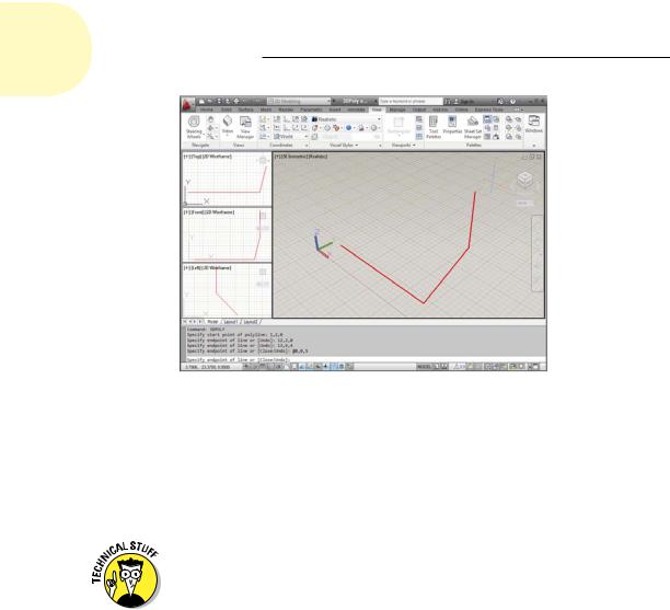
The command sequence for drawing 3D segments with the LINE or 3DPOLY command is the same as for drawing 2D segments with the LINE or PLINE command; see Chapter 8 if you need a refresher on drawing lines. The only difference is that you specify 3D coordinates instead of 2D ones. Figure 22-6 shows an example.
Creating 2D representations in this way is straightforward, although tedious, for all but the simplest objects. More important, a wireframe model becomes increasingly difficult to decipher as the complexity of the model increases.
You see a mass of lines representing the edges, and you have difficulty telling which parts of which edges are in front of others. To reduce this visual confusion, you need to graduate to surface or solid modeling commands. We introduce you to solid modeling in subsequent sections of this chapter.
www.it-ebooks.info
502 Part V: On a 3D Spree
Figure 22-6: Entering 3D coordinates to draw a 3D polyline.
Gaining a solid foundation
Solid modeling is in many ways the culmination of 3D CAD. Solids more accurately represent most real-world objects than do wireframes or surfaces. And even when representational accuracy isn’t the main issue, it’s easier to construct many kinds of models with solids.
Many special-purpose solid modeling programs use a combination of solid and surface modeling techniques for maximum flexibility in constructing and editing 3D models. These kinds of programs — and solid modeling in general — are especially popular in mechanical design.
Constructing the basic building blocks — or solid primitives — for a solid model in AutoCAD isn’t difficult. Just follow these steps:
1.Define a suitable UCS (user coordinate system).
The UCS controls the construction plane and basic 3D orientation of the solid. Read about changing planes in Chapter 21.
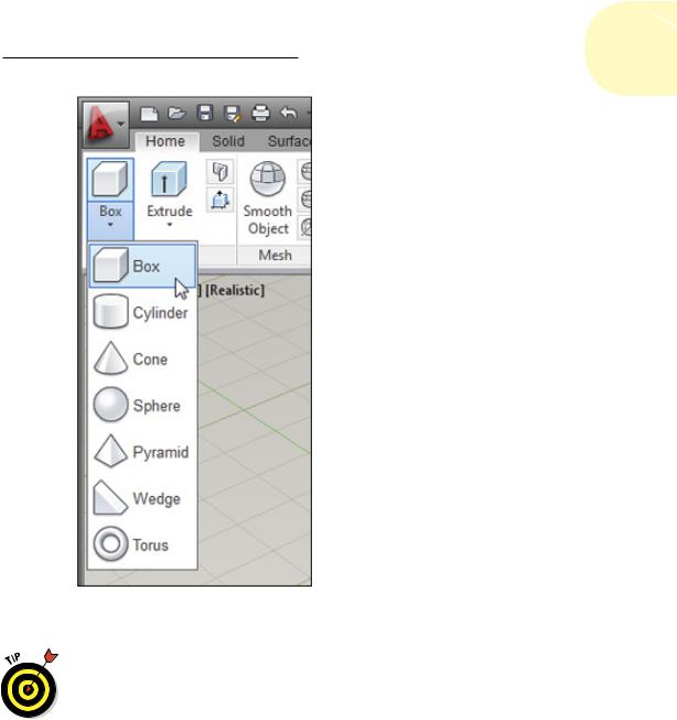
2.Click the leftmost button on the Modeling panel of the Home tab, and then choose a solid primitive from the lower half of the split button.
As shown in Figure 22-7, your choices are Box, Cylinder, Cone, Sphere, Pyramid, Wedge, and Torus.
www.it-ebooks.info
Chapter 22: From Drawings to Models 503
Figure 22-7: Everything you need for a solid foundation.
When you see a 3D object in a drawing, you can’t tell by looking whether it’s a 2D extruded object, surface mesh, or solid. If you want to find out, open the Properties palette and select the object. The drop-down list at the top of the palette shows the type of object that you selected.
Drawing solid primitives
Solids are the easiest kinds of object to work with if you’re new to 3D. The two types of 3D solid object are
www.it-ebooks.info