- •About the Authors
- •Dedication
- •Authors’ Acknowledgments
- •Table of Contents
- •Introduction
- •What’s Not (And What Is) in This Book
- •Mac attack!
- •Who Do We Think You Are?
- •How This Book Is Organized
- •Part I: AutoCAD 101
- •Part II: Let There Be Lines
- •Part III: If Drawings Could Talk
- •Part IV: Advancing with AutoCAD
- •Part V: On a 3D Spree
- •Part VI: The Part of Tens
- •But wait . . . there’s more!
- •Icons Used in This Book
- •A Few Conventions — Just in Case
- •Commanding from the keyboard
- •Tying things up with the Ribbon
- •Where to Go from Here
- •Why AutoCAD?
- •The Importance of Being DWG
- •Seeing the LT
- •Checking System Requirements
- •Suddenly, It’s 2013!
- •AutoCAD Does Windows (And Office)
- •And They’re Off: AutoCAD’s Opening Screens
- •Running with Ribbons
- •Getting with the Program
- •Looking for Mr. Status Bar
- •Let your fingers do the talking: The command window
- •The key(board) to AutoCAD success
- •Keeping tabs on palettes
- •Down the main stretch: The drawing area
- •Fun with F1
- •A Simple Setup
- •Drawing a (Base) Plate
- •Drawing rectangles on the right layers
- •Circling your plate
- •Nuts to you
- •Getting a Closer Look with Zoom and Pan
- •Modifying to Make It Merrier
- •Hip-hip-array!
- •Stretching out
- •Crossing your hatches
- •Following the Plot
- •A Setup Roadmap
- •Choosing your units
- •Weighing up your scales
- •Thinking annotatively
- •Thinking about paper
- •Defending your border
- •A Template for Success
- •Making the Most of Model Space
- •Setting your units
- •Making the drawing area snap-py (and grid-dy)
- •Setting linetype and dimension scales
- •Entering drawing properties
- •Making Templates Your Own
- •Setting Up a Layout in Paper Space
- •Will that be tabs or buttons?
- •View layouts Quick(View)ly
- •Creating a layout
- •Copying and changing layouts
- •Lost in paper space
- •Spaced out
- •A view(port) for drawing in
- •About Paper Space Layouts and Plotting
- •Managing Your Properties
- •Layer one on me!
- •Accumulating properties
- •Creating new layers
- •Manipulating layers
- •Using Named Objects
- •Using AutoCAD DesignCenter
- •Copying layers between drawings
- •Controlling Your Precision
- •Keyboard capers: Coordinate input
- •Understanding AutoCAD’s coordinate systems
- •Grab an object and make it snappy
- •Other Practical Precision Procedures
- •Introducing the AutoCAD Drawing Commands
- •The Straight and Narrow: Lines, Polylines, and Polygons
- •Toeing the line
- •Connecting the lines with polyline
- •Squaring off with rectangles
- •Choosing your sides with polygon
- •(Throwing) Curves
- •Going full circle
- •Arc-y-ology
- •Solar ellipses
- •Splines: The sketchy, sinuous curves
- •Donuts: The circles with a difference
- •Revision clouds on the horizon
- •Scoring Points
- •Commanding and Selecting
- •Command-first editing
- •Selection-first editing
- •Direct object manipulation
- •Choosing an editing style
- •Grab It
- •One-by-one selection
- •Selection boxes left and right
- •Perfecting Selecting
- •AutoCAD Groupies
- •Object Selection: Now You See It . . .
- •Get a Grip
- •About grips
- •A gripping example
- •Move it!
- •Copy, or a kinder, gentler Move
- •A warm-up stretch
- •Your AutoCAD Toolkit
- •The Big Three: Move, Copy, and Stretch
- •Base points and displacements
- •Move
- •Copy
- •Copy between drawings
- •Stretch
- •More Manipulations
- •Mirror
- •Rotate
- •Scale
- •Array
- •Offset
- •Slicing, Dicing, and Splicing
- •Trim and Extend
- •Break
- •Fillet and Chamfer and Blend
- •Join
- •When Editing Goes Bad
- •Zoom and Pan with Glass and Hand
- •The wheel deal
- •Navigating your drawing
- •Controlling your cube
- •Time to zoom
- •A View by Any Other Name . . .
- •Looking Around in Layout Land
- •Degenerating and Regenerating
- •Getting Ready to Write
- •Simply stylish text
- •Taking your text to new heights
- •One line or two?
- •Your text will be justified
- •Using the Same Old Line
- •Turning On Your Annotative Objects
- •Saying More in Multiline Text
- •Making it with Mtext
- •It slices; it dices . . .
- •Doing a number on your Mtext lists
- •Line up in columns — now!
- •Modifying Mtext
- •Gather Round the Tables
- •Tables have style, too
- •Creating and editing tables
- •Take Me to Your Leader
- •Electing a leader
- •Multi options for multileaders
- •How Do You Measure Up?
- •A Field Guide to Dimensions
- •The lazy drafter jumps over to the quick dimension commands
- •Dimension associativity
- •Where, oh where, do my dimensions go?
- •The Latest Styles in Dimensioning
- •Creating and managing dimension styles
- •Let’s get stylish!
- •Adjusting style settings
- •Size Matters
- •Details at other scales
- •Editing Dimensions
- •Editing dimension geometry
- •Editing dimension text
- •Controlling and editing dimension associativity
- •Batten Down the Hatches!
- •Don’t Count Your Hatches. . .
- •Size Matters!
- •We can do this the hard way. . .
- •. . . or we can do this the easy way
- •Annotative versus non-annotative
- •Pushing the Boundary (Of) Hatch
- •Your hatching has no style!
- •Hatch from scratch
- •Editing Hatch Objects
- •You Say Printing, We Say Plotting
- •The Plot Quickens
- •Plotting success in 16 steps
- •Get with the system
- •Configure it out
- •Preview one, two
- •Instead of fit, scale it
- •Plotting the Layout of the Land
- •Plotting Lineweights and Colors
- •Plotting with style
- •Plotting through thick and thin
- •Plotting in color
- •It’s a (Page) Setup!
- •Continuing the Plot Dialog
- •The Plot Sickens
- •Rocking with Blocks
- •Creating Block Definitions
- •Inserting Blocks
- •Attributes: Fill-in-the-Blank Blocks
- •Creating attribute definitions
- •Defining blocks that contain attribute definitions
- •Inserting blocks that contain attribute definitions
- •Edit attribute values
- •Extracting data
- •Exploding Blocks
- •Purging Unused Block Definitions
- •Arraying Associatively
- •Comparing the old and new ARRAY commands
- •Hip, hip, array!
- •Associatively editing
- •Going External
- •Becoming attached to your xrefs
- •Layer-palooza
- •Creating and editing an external reference file
- •Forging an xref path
- •Managing xrefs
- •Blocks, Xrefs, and Drawing Organization
- •Mastering the Raster
- •Attaching a raster image
- •Maintaining your image
- •Theme and Variations: Dynamic Blocks
- •Lights! Parameters!! Actions!!!
- •Manipulating dynamic blocks
- •Maintaining Design Intent
- •Defining terms
- •Forget about drawing with precision!
- •Constrain yourself
- •Understanding Geometric Constraints
- •Applying a little more constraint
- •AutoConstrain yourself!
- •Understanding Dimensional Constraints
- •Practice a little constraint
- •Making your drawing even smarter
- •Using the Parameters Manager
- •Dimensions or constraints — have it both ways!
- •The Internet and AutoCAD: An Overview
- •You send me
- •Send it with eTransmit
- •Rapid eTransmit
- •Bad reception?
- •Help from the Reference Manager
- •Design Web Format — Not Just for the Web
- •All about DWF and DWFx
- •Autodesk Design Review 2013
- •The Drawing Protection Racket
- •Autodesk Weather Forecast: Increasing Cloud
- •Working Solidly in the Cloud
- •Free AutoCAD!
- •Going once, going twice, going 123D
- •Your head planted firmly in the cloud
- •The pros
- •The cons
- •Cloudy with a shower of DWGs
- •AutoCAD 2013 cloud connectivity
- •Tomorrow’s Forecast
- •Understanding 3D Digital Models
- •Tools of the Trade
- •Warp speed ahead
- •Entering the third dimension
- •Untying the Ribbon and opening some palettes
- •Modeling from Above
- •Using 3D coordinate input
- •Using point filters
- •Object snaps and object snap tracking
- •Changing Planes
- •Displaying the UCS icon
- •Adjusting the UCS
- •Navigating the 3D Waters
- •Orbit à go-go
- •Taking a spin around the cube
- •Grabbing the SteeringWheels
- •Visualizing 3D Objects
- •Getting Your 3D Bearings
- •Creating a better 3D template
- •Seeing the world from new viewpoints
- •From Drawing to Modeling in 3D
- •Drawing basic 3D objects
- •Gaining a solid foundation
- •Drawing solid primitives
- •Adding the Third Dimension to 2D Objects
- •Creating 3D objects from 2D drawings
- •Modifying 3D Objects
- •Selecting subobjects
- •Working with gizmos
- •More 3D variants of 2D commands
- •Editing solids
- •Get the 2D Out of Here!
- •A different point of view
- •But wait! There’s more!
- •But wait! There’s less!
- •Do You See What I See?
- •Visualizing the Digital World
- •Adding Lighting
- •Default lighting
- •User-defined lights
- •Sunlight
- •Creating and Applying Materials
- •Defining a Background
- •Rendering a 3D Model
- •Autodesk Feedback Community
- •Autodesk Discussion Groups
- •Autodesk’s Own Bloggers
- •Autodesk University
- •The Autodesk Channel on YouTube
- •The World Wide (CAD) Web
- •Your Local ATC
- •Your Local User Group
- •AUGI
- •Books
- •Price
- •3D Abilities
- •Customization Options
- •Network Licensing
- •Express Tools
- •Parametrics
- •Standards Checking
- •Data Extraction
- •MLINE versus DLINE
- •Profiles
- •Reference Manager
- •And The Good News Is . . .
- •APERTURE
- •DIMASSOC
- •MENUBAR
- •MIRRTEXT
- •OSNAPZ
- •PICKBOX
- •REMEMBERFOLDERS
- •ROLLOVERTIPS
- •TOOLTIPS
- •VISRETAIN
- •And the Bonus Round
- •Index
Chapter 11: Edit for Credit 223
Copy between drawings
You can’t copy or move objects from one drawing to another with the COPY command. Instead, you use the COPYCLIP or CUTCLIP commands together with their companion command, PASTECLIP.
COPYCLIP, CUTCLIP, and PASTECLIP use the Windows Clipboard to temporarily store drawing objects from one file so they can be pasted into another file. The Clipboard panel on the Ribbon contains Cut, Copy, and Paste tools, the three standard Clipboard buttons you find in every Windows program.
As you’re figuring out where things are lurking in the AutoCAD 2013 Ribbon, remember that the standard Windows keyboard shortcuts — Ctrl+X (cut), Ctrl+C (copy), and Ctrl+V (paste) — are still available and are often the most efficient way of using the Windows Clipboard — even after you’ve found the Clipboard panel!
Table 11-2 summarizes AutoCAD’s most important Clipboard-related commands, along with the equivalent choices on the right-click menu and Ribbon’s Clipboard panel. (The Classic Standard toolbar buttons’ tooltips display the same names.)
Table 11-2 |
AutoCAD Clipboard Commands |
|
|
Command Name |
Right-Click |
Clipboard Panel |
Classic |
|
Menu |
|
Standard |
|
|
|
Toolbar |
CUTCLIP (Ctrl+X) |
Cut |
Cut |
Cut |
|
|
|
|
COPYCLIP (Ctrl+C) |
Copy |
Copy Clip |
Copy |
|
|
|
|
COPYBASE |
Copy with Base |
Not available |
Not |
(Ctrl+Shift+C) |
Point |
|
available |
COPYLINK |
Not available |
Not available |
Not |
|
|
|
available |
PASTECLIP (Ctrl+V) |
Paste |
Paste |
Paste |
|
|
|
|
PASTEBLOCK |
Paste as Block |
Paste as Block (on |
Not |
(Ctrl+Shift+V) |
|
Paste flyout) |
available |
PASTEAS |
Not available |
Paste as Hyperlink |
Not |
HYPERLINK |
|
(on Paste flyout) |
available |
PASTEORIG |
Paste to |
Paste to Original |
Not |
|
Original |
Coordinates (on |
available |
|
Coordinates |
Paste flyout) |
|
PASTESPEC |
Not available |
Paste Special (on |
Not |
|
|
Paste flyout) |
available |
www.it-ebooks.info
224 Part II: Let There Be Lines
Stretch
The STRETCH command is superficially similar to COPY and MOVE; it has the same interesting base point and displacement prompts, and it shifts objects to other locations in the drawing. But it also has one big important difference: It can move one end of one or more objects, leaving the other end or ends where they are so you can use it to change the length of lines, for example. Here are the things you need to know to make STRETCH your friend:
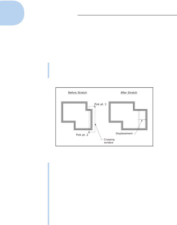
Selecting objects to stretch: To use STRETCH to change the length of objects, you must select objects by using a crossing selection box (or crossing polygon), as described in Chapter 10. See Figure 11-3 for a visual explanation.
Figure 11-3: Use a crossing selection box to select objects for stretching.
Defining points: STRETCH operates on the defining points of objects — endpoints of a line, vertices of a polyline, the center of a circle, and so on — according to the following rule: If a defining point is within the crossing selection box that you specify, AutoCAD moves the defining point and updates the object accordingly.
For example, if your crossing selection box surrounds one endpoint of a line but not the other endpoint, STRETCH moves the selected endpoint and redraws the line in the new position dictated by the selected endpoint’s new location. It’s as though you have a rubber band tacked to the wall with two pins, and you move one of the pins.
Compressing and stretching: STRETCH can make lines longer or shorter, depending on your crossing selection box and displacement vector. In other words, the STRETCH command really combines stretching and compressing.
www.it-ebooks.info
Chapter 11: Edit for Credit 225
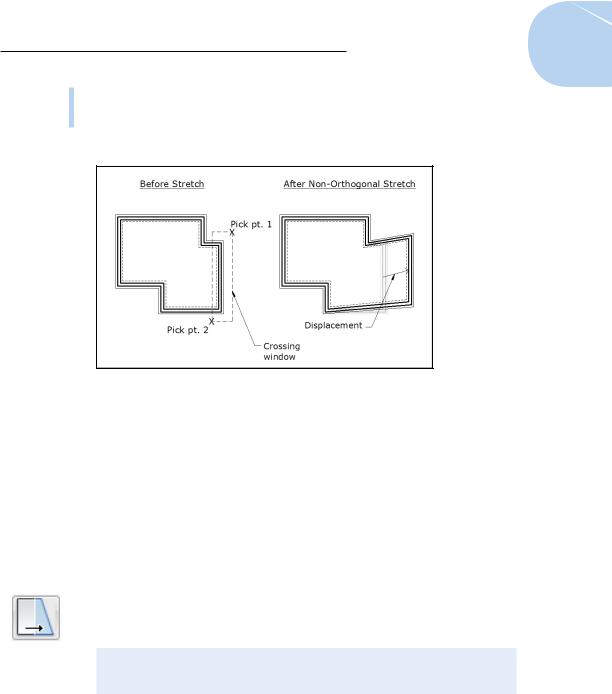
Getting in the mode: Depending on what you’re trying to accomplish, you may want to turn on Ortho or Polar Tracking mode before stretching. Figure 11-4 shows the results of an Ortho and a non-Ortho stretch.
Figure 11-4: The hazards of stretching without ortho or polar tracking turned on.
The following steps describe how to stretch lines:
1.Draw some lines in an arrangement similar to the dark lines shown in Figure 11-5.
Start your stretching with simple objects. You can work up to more complicated objects — polylines, arcs, and so on — after you’ve limbered up with lines.
2.Press Esc to make sure that no command is active and no objects are selected.
3.Click the Stretch button on the Modify panel of the Ribbon’s Home tab.
The command line displays the Select objects prompt with a warning to use the Crossing or CPolygon object-selection mode:
Select objects to stretch by crossing-window or crossingpolygon...
Select objects:
4.Pick points to specify a crossing selection box that encloses some, but not all, endpoints of the lines.
Figure 11-5 shows a sample crossing selection box that completely encloses the two vertical lines on the right side of the figure. This crossing selection box cuts through the four horizontal lines, enclosing only one endpoint of each.
www.it-ebooks.info
226 Part II: Let There Be Lines
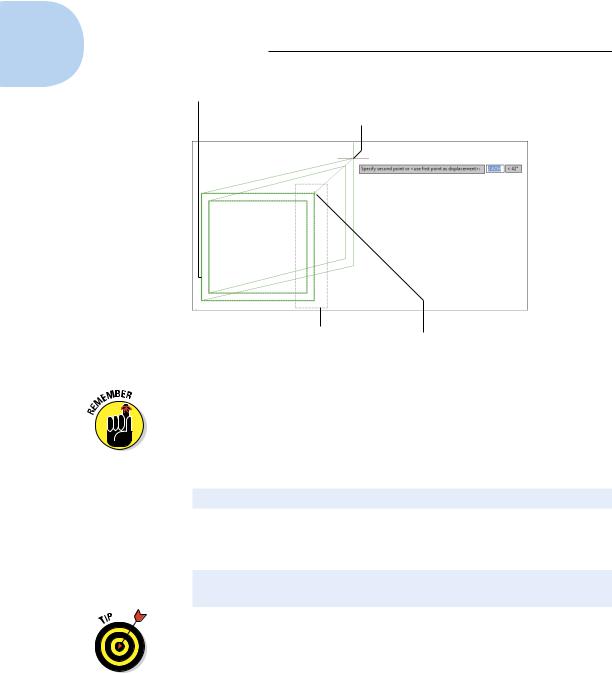
Unselected lines don’t move.
Selected lines being dragged to new location
Crossing window |
Crossing window |
pick point 2 |
pick point 1 |
Figure 11-5: Dragging objects in the middle of the STRETCH command.
You specify a crossing selection box by picking a point, moving your mouse to the left, and picking a second point.
5. Press Enter to end object selection.
AutoCAD displays the following prompt:
Specify base point or [Displacement] <Displacement>:
6.Specify a base point by object snapping to a point on an existing object or by typing absolute X,Y coordinates.
AutoCAD displays the following prompt:
Specify second point or <use first point as displacement>:
Toggle Ortho mode on and then off by clicking the Ortho Mode button on the status bar; try moving the crosshairs around first with Ortho on and then with it off to see the difference.
Figure 11-5 shows what the screen looks like as you move the crosshairs around without benefit of ortho or polar tracking.
7.Toggle Ortho mode on (if it isn’t already), and then specify the second point — usually by using direct distance entry.
You can also specify the second point by object snapping to a point on an existing object or by typing relative X,Y coordinates.
www.it-ebooks.info