

- •About the Authors
- •Dedication
- •Authors’ Acknowledgments
- •Table of Contents
- •Introduction
- •What’s Not (And What Is) in This Book
- •Mac attack!
- •Who Do We Think You Are?
- •How This Book Is Organized
- •Part I: AutoCAD 101
- •Part II: Let There Be Lines
- •Part III: If Drawings Could Talk
- •Part IV: Advancing with AutoCAD
- •Part V: On a 3D Spree
- •Part VI: The Part of Tens
- •But wait . . . there’s more!
- •Icons Used in This Book
- •A Few Conventions — Just in Case
- •Commanding from the keyboard
- •Tying things up with the Ribbon
- •Where to Go from Here
- •Why AutoCAD?
- •The Importance of Being DWG
- •Seeing the LT
- •Checking System Requirements
- •Suddenly, It’s 2013!
- •AutoCAD Does Windows (And Office)
- •And They’re Off: AutoCAD’s Opening Screens
- •Running with Ribbons
- •Getting with the Program
- •Looking for Mr. Status Bar
- •Let your fingers do the talking: The command window
- •The key(board) to AutoCAD success
- •Keeping tabs on palettes
- •Down the main stretch: The drawing area
- •Fun with F1
- •A Simple Setup
- •Drawing a (Base) Plate
- •Drawing rectangles on the right layers
- •Circling your plate
- •Nuts to you
- •Getting a Closer Look with Zoom and Pan
- •Modifying to Make It Merrier
- •Hip-hip-array!
- •Stretching out
- •Crossing your hatches
- •Following the Plot
- •A Setup Roadmap
- •Choosing your units
- •Weighing up your scales
- •Thinking annotatively
- •Thinking about paper
- •Defending your border
- •A Template for Success
- •Making the Most of Model Space
- •Setting your units
- •Making the drawing area snap-py (and grid-dy)
- •Setting linetype and dimension scales
- •Entering drawing properties
- •Making Templates Your Own
- •Setting Up a Layout in Paper Space
- •Will that be tabs or buttons?
- •View layouts Quick(View)ly
- •Creating a layout
- •Copying and changing layouts
- •Lost in paper space
- •Spaced out
- •A view(port) for drawing in
- •About Paper Space Layouts and Plotting
- •Managing Your Properties
- •Layer one on me!
- •Accumulating properties
- •Creating new layers
- •Manipulating layers
- •Using Named Objects
- •Using AutoCAD DesignCenter
- •Copying layers between drawings
- •Controlling Your Precision
- •Keyboard capers: Coordinate input
- •Understanding AutoCAD’s coordinate systems
- •Grab an object and make it snappy
- •Other Practical Precision Procedures
- •Introducing the AutoCAD Drawing Commands
- •The Straight and Narrow: Lines, Polylines, and Polygons
- •Toeing the line
- •Connecting the lines with polyline
- •Squaring off with rectangles
- •Choosing your sides with polygon
- •(Throwing) Curves
- •Going full circle
- •Arc-y-ology
- •Solar ellipses
- •Splines: The sketchy, sinuous curves
- •Donuts: The circles with a difference
- •Revision clouds on the horizon
- •Scoring Points
- •Commanding and Selecting
- •Command-first editing
- •Selection-first editing
- •Direct object manipulation
- •Choosing an editing style
- •Grab It
- •One-by-one selection
- •Selection boxes left and right
- •Perfecting Selecting
- •AutoCAD Groupies
- •Object Selection: Now You See It . . .
- •Get a Grip
- •About grips
- •A gripping example
- •Move it!
- •Copy, or a kinder, gentler Move
- •A warm-up stretch
- •Your AutoCAD Toolkit
- •The Big Three: Move, Copy, and Stretch
- •Base points and displacements
- •Move
- •Copy
- •Copy between drawings
- •Stretch
- •More Manipulations
- •Mirror
- •Rotate
- •Scale
- •Array
- •Offset
- •Slicing, Dicing, and Splicing
- •Trim and Extend
- •Break
- •Fillet and Chamfer and Blend
- •Join
- •When Editing Goes Bad
- •Zoom and Pan with Glass and Hand
- •The wheel deal
- •Navigating your drawing
- •Controlling your cube
- •Time to zoom
- •A View by Any Other Name . . .
- •Looking Around in Layout Land
- •Degenerating and Regenerating
- •Getting Ready to Write
- •Simply stylish text
- •Taking your text to new heights
- •One line or two?
- •Your text will be justified
- •Using the Same Old Line
- •Turning On Your Annotative Objects
- •Saying More in Multiline Text
- •Making it with Mtext
- •It slices; it dices . . .
- •Doing a number on your Mtext lists
- •Line up in columns — now!
- •Modifying Mtext
- •Gather Round the Tables
- •Tables have style, too
- •Creating and editing tables
- •Take Me to Your Leader
- •Electing a leader
- •Multi options for multileaders
- •How Do You Measure Up?
- •A Field Guide to Dimensions
- •The lazy drafter jumps over to the quick dimension commands
- •Dimension associativity
- •Where, oh where, do my dimensions go?
- •The Latest Styles in Dimensioning
- •Creating and managing dimension styles
- •Let’s get stylish!
- •Adjusting style settings
- •Size Matters
- •Details at other scales
- •Editing Dimensions
- •Editing dimension geometry
- •Editing dimension text
- •Controlling and editing dimension associativity
- •Batten Down the Hatches!
- •Don’t Count Your Hatches. . .
- •Size Matters!
- •We can do this the hard way. . .
- •. . . or we can do this the easy way
- •Annotative versus non-annotative
- •Pushing the Boundary (Of) Hatch
- •Your hatching has no style!
- •Hatch from scratch
- •Editing Hatch Objects
- •You Say Printing, We Say Plotting
- •The Plot Quickens
- •Plotting success in 16 steps
- •Get with the system
- •Configure it out
- •Preview one, two
- •Instead of fit, scale it
- •Plotting the Layout of the Land
- •Plotting Lineweights and Colors
- •Plotting with style
- •Plotting through thick and thin
- •Plotting in color
- •It’s a (Page) Setup!
- •Continuing the Plot Dialog
- •The Plot Sickens
- •Rocking with Blocks
- •Creating Block Definitions
- •Inserting Blocks
- •Attributes: Fill-in-the-Blank Blocks
- •Creating attribute definitions
- •Defining blocks that contain attribute definitions
- •Inserting blocks that contain attribute definitions
- •Edit attribute values
- •Extracting data
- •Exploding Blocks
- •Purging Unused Block Definitions
- •Arraying Associatively
- •Comparing the old and new ARRAY commands
- •Hip, hip, array!
- •Associatively editing
- •Going External
- •Becoming attached to your xrefs
- •Layer-palooza
- •Creating and editing an external reference file
- •Forging an xref path
- •Managing xrefs
- •Blocks, Xrefs, and Drawing Organization
- •Mastering the Raster
- •Attaching a raster image
- •Maintaining your image
- •Theme and Variations: Dynamic Blocks
- •Lights! Parameters!! Actions!!!
- •Manipulating dynamic blocks
- •Maintaining Design Intent
- •Defining terms
- •Forget about drawing with precision!
- •Constrain yourself
- •Understanding Geometric Constraints
- •Applying a little more constraint
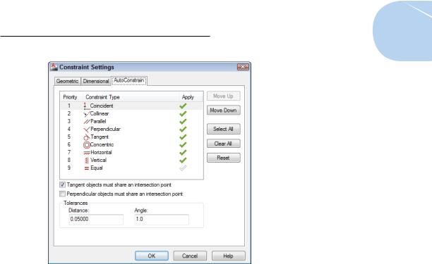
- •AutoConstrain yourself!
- •Understanding Dimensional Constraints
- •Practice a little constraint
- •Making your drawing even smarter
- •Using the Parameters Manager
- •Dimensions or constraints — have it both ways!
- •The Internet and AutoCAD: An Overview
- •You send me
- •Send it with eTransmit
- •Rapid eTransmit
- •Bad reception?
- •Help from the Reference Manager
- •Design Web Format — Not Just for the Web
- •All about DWF and DWFx
- •Autodesk Design Review 2013
- •The Drawing Protection Racket
- •Autodesk Weather Forecast: Increasing Cloud
- •Working Solidly in the Cloud
- •Free AutoCAD!
- •Going once, going twice, going 123D
- •Your head planted firmly in the cloud
- •The pros
- •The cons
- •Cloudy with a shower of DWGs
- •AutoCAD 2013 cloud connectivity
- •Tomorrow’s Forecast
- •Understanding 3D Digital Models
- •Tools of the Trade
- •Warp speed ahead
- •Entering the third dimension
- •Untying the Ribbon and opening some palettes
- •Modeling from Above
- •Using 3D coordinate input
- •Using point filters
- •Object snaps and object snap tracking
- •Changing Planes
- •Displaying the UCS icon
- •Adjusting the UCS
- •Navigating the 3D Waters
- •Orbit à go-go
- •Taking a spin around the cube
- •Grabbing the SteeringWheels
- •Visualizing 3D Objects
- •Getting Your 3D Bearings
- •Creating a better 3D template
- •Seeing the world from new viewpoints
- •From Drawing to Modeling in 3D
- •Drawing basic 3D objects
- •Gaining a solid foundation
- •Drawing solid primitives
- •Adding the Third Dimension to 2D Objects
- •Creating 3D objects from 2D drawings
- •Modifying 3D Objects
- •Selecting subobjects
- •Working with gizmos
- •More 3D variants of 2D commands
- •Editing solids
- •Get the 2D Out of Here!
- •A different point of view
- •But wait! There’s more!
- •But wait! There’s less!
- •Do You See What I See?
- •Visualizing the Digital World
- •Adding Lighting
- •Default lighting
- •User-defined lights
- •Sunlight
- •Creating and Applying Materials
- •Defining a Background
- •Rendering a 3D Model
- •Autodesk Feedback Community
- •Autodesk Discussion Groups
- •Autodesk’s Own Bloggers
- •Autodesk University
- •The Autodesk Channel on YouTube
- •The World Wide (CAD) Web
- •Your Local ATC
- •Your Local User Group
- •AUGI
- •Books
- •Price
- •3D Abilities
- •Customization Options
- •Network Licensing
- •Express Tools
- •Parametrics
- •Standards Checking
- •Data Extraction
- •MLINE versus DLINE
- •Profiles
- •Reference Manager
- •And The Good News Is . . .
- •APERTURE
- •DIMASSOC
- •MENUBAR
- •MIRRTEXT
- •OSNAPZ
- •PICKBOX
- •REMEMBERFOLDERS
- •ROLLOVERTIPS
- •TOOLTIPS
- •VISRETAIN
- •And the Bonus Round
- •Index
Chapter 19: Call the Parametrics! 435
Figure 19-7: Auto-constrainable geometric relations in the Constraint Settings dialog box.
Understanding Dimensional Constraints
The normal practice in AutoCAD is to create some geometry — of course, using all the precision techniques we discuss in Chapter 7 — and then apply dimensions as we describe in Chapter 14. Assuming that you’re using fully associative dimensions, you can then edit the geometry and watch the dimensions update automatically. The length of the line or the radius of
the circle are in control, and those dimensions are called driven dimensions because they change when the object geometry changes.
Dimensional constraints, unlike regular AutoCAD dimensions, are driving dimensions, which means that when you change the value of a dynamic dimension on a line, the line changes to match. In other words, the dimension is driving the length of the line, not the other way around.
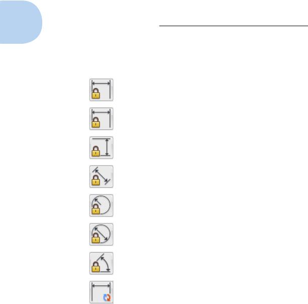
There are only eight dimensional-constraint options, but they cover all the bases. Table 19-2 lists them and describes their purposes.
www.it-ebooks.info
436 Part IV: Advancing with AutoCAD
Table 19-2 |
|
Dimensional Constraints |
Button Icon |
Constraint |
Description |
|
Name |
|
|
Linear |
Applies a horizontal or vertical dimensional |
|
|
constraint (similar to DIMLINEAR) |
|
|
|
|
Horizontal |
Applies a dimensional constraint aligned with |
|
|
the X axis of the coordinate system (similar to |
|
|
DIMLINEAR’s Horizontal option) |
|
|
|
|
Vertical |
Applies a dimensional constraint aligned with |
|
|
the Y axis of the coordinate system (similar to |
|
|
DIMLINEAR’s Vertical option) |
|
|
|
|
Aligned |
Applies a dimensional constraint aligned with |
|
|
the object or with the points being dimensioned |
|
|
(similar to DIMALIGNED) |
|
|
|
|
Radial |
Applies a set value or formula to the radius of |
|
|
an arc or a circle (similar to DIMRADIUS) |
|
|
|
|
Diameter |
Applies a set value or formula to the diameter |
|
|
of an arc or a circle (similar to DIMDIAMETER) |
|
|
|
|
Angular |
Applies a set value or formula to the angle |
|
|
between two lines or three points (similar to |
|
|
DIMANGULAR) |
|
|
|
|
Convert |
Converts an existing associative dimension |
|
|
object to a dimensional constraint |
|
|
|
Practice a little constraint
The objects that you add to your drawing from the Dimensional panel are not the same as the dimension objects you add from the Annotate tab. Dimensional constraints are driving dimensions, meaning that when you change the value of one of these dimensions, the geometry changes.
www.it-ebooks.info
Chapter 19: Call the Parametrics! 437
A lot is happening behind the scenes as you apply parametric constraints. You can get a great sense of how these constraints work at keeping your drawing objects in order by trying the STRETCH command on objects after you apply a constraint to them.
You can find the files we use in this sequence of steps at this book’s companion website. Go to www.dummies.com/go/autocad2013fd and download afd19.zip. The drawing named afd19a.dwg contains the unconstrained geometry, and drawing afd19b.dwg contains the end product.
The following steps present a very simple example of dimensional constraints:
1.Start a new drawing and make the Ribbon’s Parametric tab current.
Turn on some appropriate precision drawing aids on the status bar, such as Snap, Ortho, and Osnap.
2.Draw some reasonably precise geometry by using some of those precision techniques we describe in earlier chapters.
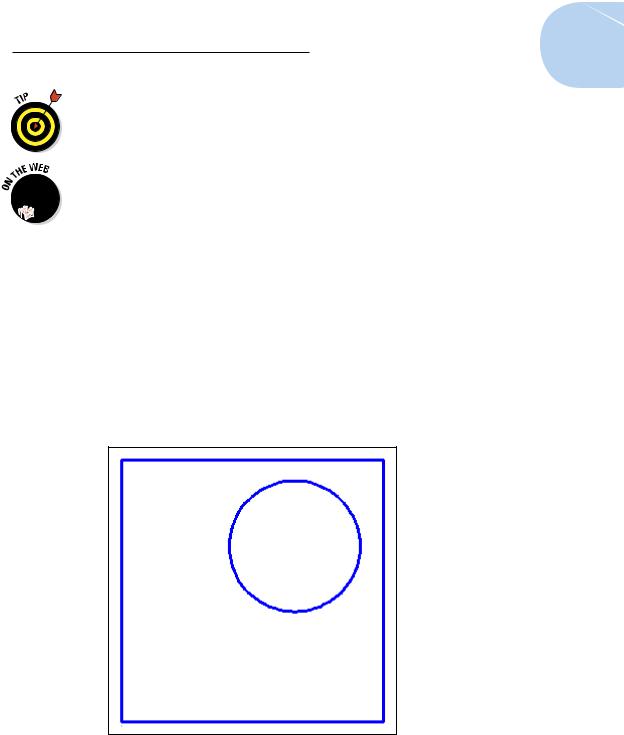
In the following example, we use the RECTANG and CIRCLE commands to draw the geometry you see in Figure 19-8. The rectangle is 10 units square, and the 2.5-unit–radius circle is deliberately drawn away from the middle of the square.
Figure 19-8: Simple geometry badly in need of constraining.
www.it-ebooks.info
438 Part IV: Advancing with AutoCAD
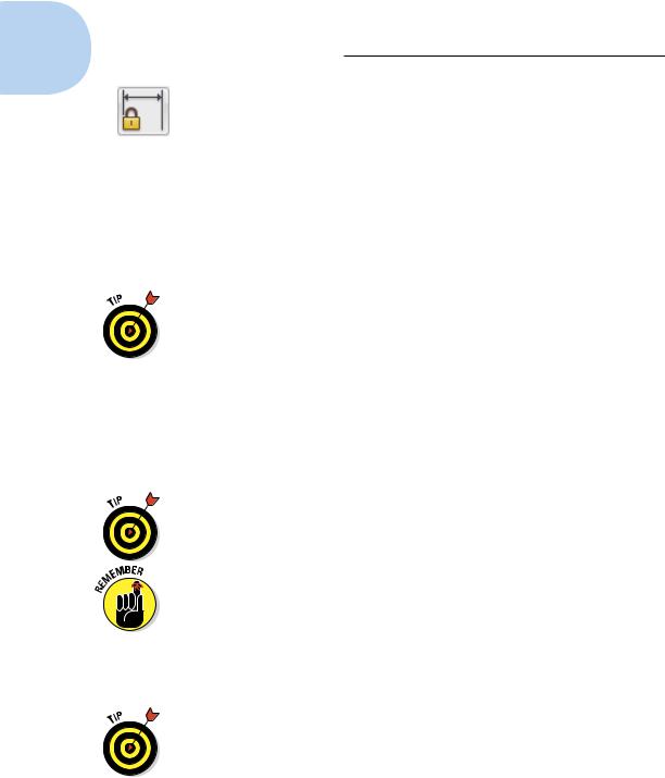
3.On the Dimensional panel of the Parametric tab, click the top part of the Linear split button.
A linear dimension icon appears beside the pickbox, and AutoCAD prompts you to specify the first constraint point or to pick an object.
Just like the DIMLINEAR command, the Linear dimensional constraint tool is inferential: that is, which way you drag the crosshairs controls whether you get a horizontal or vertical dimension. Also, just like DIMLINEAR, you can press Enter at the command prompt and select an object to dimension.
4.Press Enter at the command prompt to confirm that you want to select an object and then select the bottom horizontal line segment.
If you see red markers at the midpoint and ends of the bottom line, you didn’t press Enter, and you’re in point-selection rather than objectselection mode.
AutoCAD generates a preview of a dimensional constraint and prompts you for a location.
5.Click to locate the dimension position.
AutoCAD draws a dimensional constraint with a highlighted text field displaying the dimension name (d1 in this example) and the value returned by AutoCAD. You could type a new value in the edit box, but for now, just press Enter to confirm the value and the dimension location (see Figure 19-9).
If your dimensional constraints disappear as soon as you place them, click the Show All button on the Parametric tab’s Dimensional panel (refer to Figure 19-1).
Dimensional constraints are not regular dimension objects — they’re not going to plot, so it doesn’t really matter where you put them or what they look like. (We show you how to turn dimensional constraints into properly styled, plottable dimensions in the next section.)
6.Repeat Steps 3 through 5 and add a dimensional constraint to the right vertical edge of the rectangle.
AutoCAD draws a second dimensional constraint, this one named d2.
As you mouse over the Linear button, you can see that unlike its Aligned neighbor, it’s split into two parts. You can force a linear dimensional constraint to be either horizontal or vertical (rather than dependent on the direction in which you drag your crosshairs) by clicking the bottom part of the Linear button and making your choice from the drop-down menu.
www.it-ebooks.info