

- •About the Authors
- •Dedication
- •Authors’ Acknowledgments
- •Table of Contents
- •Introduction
- •What’s Not (And What Is) in This Book
- •Mac attack!
- •Who Do We Think You Are?
- •How This Book Is Organized
- •Part I: AutoCAD 101
- •Part II: Let There Be Lines
- •Part III: If Drawings Could Talk
- •Part IV: Advancing with AutoCAD
- •Part V: On a 3D Spree
- •Part VI: The Part of Tens
- •But wait . . . there’s more!
- •Icons Used in This Book
- •A Few Conventions — Just in Case
- •Commanding from the keyboard
- •Tying things up with the Ribbon
- •Where to Go from Here
- •Why AutoCAD?
- •The Importance of Being DWG
- •Seeing the LT
- •Checking System Requirements
- •Suddenly, It’s 2013!
- •AutoCAD Does Windows (And Office)
- •And They’re Off: AutoCAD’s Opening Screens
- •Running with Ribbons
- •Getting with the Program
- •Looking for Mr. Status Bar
- •Let your fingers do the talking: The command window
- •The key(board) to AutoCAD success
- •Keeping tabs on palettes
- •Down the main stretch: The drawing area
- •Fun with F1
- •A Simple Setup
- •Drawing a (Base) Plate
- •Drawing rectangles on the right layers
- •Circling your plate
- •Nuts to you
- •Getting a Closer Look with Zoom and Pan
- •Modifying to Make It Merrier
- •Hip-hip-array!
- •Stretching out
- •Crossing your hatches
- •Following the Plot
- •A Setup Roadmap
- •Choosing your units
- •Weighing up your scales
- •Thinking annotatively
- •Thinking about paper
- •Defending your border
- •A Template for Success
- •Making the Most of Model Space
- •Setting your units
- •Making the drawing area snap-py (and grid-dy)
- •Setting linetype and dimension scales
- •Entering drawing properties
- •Making Templates Your Own
- •Setting Up a Layout in Paper Space
- •Will that be tabs or buttons?
- •View layouts Quick(View)ly
- •Creating a layout
- •Copying and changing layouts
- •Lost in paper space
- •Spaced out
- •A view(port) for drawing in
- •About Paper Space Layouts and Plotting
- •Managing Your Properties
- •Layer one on me!
- •Accumulating properties
- •Creating new layers
- •Manipulating layers
- •Using Named Objects
- •Using AutoCAD DesignCenter
- •Copying layers between drawings
- •Controlling Your Precision
- •Keyboard capers: Coordinate input
- •Understanding AutoCAD’s coordinate systems
- •Grab an object and make it snappy
- •Other Practical Precision Procedures
- •Introducing the AutoCAD Drawing Commands
- •The Straight and Narrow: Lines, Polylines, and Polygons
- •Toeing the line
- •Connecting the lines with polyline
- •Squaring off with rectangles
- •Choosing your sides with polygon
- •(Throwing) Curves
- •Going full circle
- •Arc-y-ology
- •Solar ellipses
- •Splines: The sketchy, sinuous curves
- •Donuts: The circles with a difference
- •Revision clouds on the horizon
- •Scoring Points
- •Commanding and Selecting
- •Command-first editing
- •Selection-first editing
- •Direct object manipulation
- •Choosing an editing style
- •Grab It
- •One-by-one selection
- •Selection boxes left and right
- •Perfecting Selecting
- •AutoCAD Groupies
- •Object Selection: Now You See It . . .
- •Get a Grip
- •About grips
- •A gripping example
- •Move it!
- •Copy, or a kinder, gentler Move
- •A warm-up stretch
- •Your AutoCAD Toolkit
- •The Big Three: Move, Copy, and Stretch
- •Base points and displacements
- •Move
- •Copy
- •Copy between drawings
- •Stretch
- •More Manipulations
- •Mirror
- •Rotate
- •Scale
- •Array
- •Offset
- •Slicing, Dicing, and Splicing
- •Trim and Extend
- •Break
- •Fillet and Chamfer and Blend
- •Join
- •When Editing Goes Bad
- •Zoom and Pan with Glass and Hand
- •The wheel deal
- •Navigating your drawing
- •Controlling your cube
- •Time to zoom
- •A View by Any Other Name . . .
- •Looking Around in Layout Land
- •Degenerating and Regenerating
- •Getting Ready to Write
- •Simply stylish text
- •Taking your text to new heights
- •One line or two?
- •Your text will be justified
- •Using the Same Old Line
- •Turning On Your Annotative Objects
- •Saying More in Multiline Text
- •Making it with Mtext
- •It slices; it dices . . .
- •Doing a number on your Mtext lists
- •Line up in columns — now!
- •Modifying Mtext
- •Gather Round the Tables
- •Tables have style, too
- •Creating and editing tables
- •Take Me to Your Leader
- •Electing a leader
- •Multi options for multileaders
- •How Do You Measure Up?
- •A Field Guide to Dimensions
- •The lazy drafter jumps over to the quick dimension commands
- •Dimension associativity
- •Where, oh where, do my dimensions go?
- •The Latest Styles in Dimensioning
- •Creating and managing dimension styles
- •Let’s get stylish!
- •Adjusting style settings
- •Size Matters
- •Details at other scales
- •Editing Dimensions
- •Editing dimension geometry
- •Editing dimension text
- •Controlling and editing dimension associativity
- •Batten Down the Hatches!
- •Don’t Count Your Hatches. . .
- •Size Matters!
- •We can do this the hard way. . .
- •. . . or we can do this the easy way
- •Annotative versus non-annotative
- •Pushing the Boundary (Of) Hatch
- •Your hatching has no style!
- •Hatch from scratch
- •Editing Hatch Objects
- •You Say Printing, We Say Plotting
- •The Plot Quickens
- •Plotting success in 16 steps
- •Get with the system
- •Configure it out
- •Preview one, two
- •Instead of fit, scale it
- •Plotting the Layout of the Land
- •Plotting Lineweights and Colors
- •Plotting with style
- •Plotting through thick and thin
- •Plotting in color
- •It’s a (Page) Setup!
- •Continuing the Plot Dialog
- •The Plot Sickens
- •Rocking with Blocks
- •Creating Block Definitions
- •Inserting Blocks
- •Attributes: Fill-in-the-Blank Blocks
- •Creating attribute definitions
- •Defining blocks that contain attribute definitions
- •Inserting blocks that contain attribute definitions
- •Edit attribute values
- •Extracting data
- •Exploding Blocks
- •Purging Unused Block Definitions
- •Arraying Associatively
- •Comparing the old and new ARRAY commands
- •Hip, hip, array!
- •Associatively editing
- •Going External
- •Becoming attached to your xrefs
- •Layer-palooza
- •Creating and editing an external reference file
- •Forging an xref path
- •Managing xrefs
- •Blocks, Xrefs, and Drawing Organization
- •Mastering the Raster
- •Attaching a raster image
- •Maintaining your image
- •Theme and Variations: Dynamic Blocks
- •Lights! Parameters!! Actions!!!
- •Manipulating dynamic blocks
- •Maintaining Design Intent
- •Defining terms
- •Forget about drawing with precision!
- •Constrain yourself
- •Understanding Geometric Constraints
- •Applying a little more constraint
- •AutoConstrain yourself!
- •Understanding Dimensional Constraints
- •Practice a little constraint
- •Making your drawing even smarter
- •Using the Parameters Manager
- •Dimensions or constraints — have it both ways!
- •The Internet and AutoCAD: An Overview
- •You send me
- •Send it with eTransmit
- •Rapid eTransmit
- •Bad reception?
- •Help from the Reference Manager
- •Design Web Format — Not Just for the Web
- •All about DWF and DWFx
- •Autodesk Design Review 2013
- •The Drawing Protection Racket
- •Autodesk Weather Forecast: Increasing Cloud
- •Working Solidly in the Cloud
- •Free AutoCAD!
- •Going once, going twice, going 123D
- •Your head planted firmly in the cloud
- •The pros
- •The cons
- •Cloudy with a shower of DWGs
- •AutoCAD 2013 cloud connectivity
- •Tomorrow’s Forecast
- •Understanding 3D Digital Models
- •Tools of the Trade
- •Warp speed ahead
- •Entering the third dimension
- •Untying the Ribbon and opening some palettes
- •Modeling from Above
- •Using 3D coordinate input
- •Using point filters
- •Object snaps and object snap tracking
- •Changing Planes
- •Displaying the UCS icon
- •Adjusting the UCS
- •Navigating the 3D Waters
- •Orbit à go-go
- •Taking a spin around the cube
- •Grabbing the SteeringWheels
- •Visualizing 3D Objects
- •Getting Your 3D Bearings
- •Creating a better 3D template
- •Seeing the world from new viewpoints
- •From Drawing to Modeling in 3D
- •Drawing basic 3D objects
- •Gaining a solid foundation
- •Drawing solid primitives
- •Adding the Third Dimension to 2D Objects
- •Creating 3D objects from 2D drawings
- •Modifying 3D Objects
- •Selecting subobjects
- •Working with gizmos
- •More 3D variants of 2D commands
- •Editing solids
- •Get the 2D Out of Here!
- •A different point of view
- •But wait! There’s more!
- •But wait! There’s less!
- •Do You See What I See?
- •Visualizing the Digital World
- •Adding Lighting
- •Default lighting
- •User-defined lights
- •Sunlight
- •Creating and Applying Materials
- •Defining a Background
- •Rendering a 3D Model
- •Autodesk Feedback Community
- •Autodesk Discussion Groups
- •Autodesk’s Own Bloggers
- •Autodesk University
- •The Autodesk Channel on YouTube
- •The World Wide (CAD) Web
- •Your Local ATC
- •Your Local User Group
- •AUGI
- •Books
- •Price
- •3D Abilities
- •Customization Options
- •Network Licensing
- •Express Tools
- •Parametrics
- •Standards Checking
- •Data Extraction
- •MLINE versus DLINE
- •Profiles
- •Reference Manager
- •And The Good News Is . . .
- •APERTURE
- •DIMASSOC
- •MENUBAR
- •MIRRTEXT
- •OSNAPZ
- •PICKBOX
- •REMEMBERFOLDERS
- •ROLLOVERTIPS
- •TOOLTIPS
- •VISRETAIN
- •And the Bonus Round
- •Index
Chapter 14: Entering New Dimensions 301
Not a problem. AutoCAD controls the look of dimensions by means of dimension styles, just as it controls the look of text with text styles, and tables with table styles. In fact, AutoCAD also uses text styles to control the appearance of the text in dimensions. We cover dimension styles in more detail later in this chapter, but suffice it to say that AutoCAD has about 80 variables that can be used to warp dimensions into just about any perversion that your industry or company can imagine.
Meanwhile, look at the other basic types of dimension that AutoCAD can apply, as shown in Figure 14-2.
DIMDIAMETER(DDI)
DIMRADIUS(DRA) |
|
DIMCONTINUE(DCO) |
||||
|
|
DIMJOLINE(DLI) |
DIMANGULAR(DAN) |
|
||
|
|
|
|
|
|
|
|
|
|
|
|
|
|
|
|
|
|
|
|
|
|
|
|
|
|
|
|
|
|
|
|
|
|
|
|
|
|
|
|
|
|
|
|
|
|
|
|
|
|
|
|
|
|
|
|
|
|
|
|
|
|
DIMJOGGED(DJO) DIMLINGAR(DLI) |
DIMBASELINE(DBA) |
|||
|
|
|
|
|
DIMARC(DAR)
Figure 14-2: Examples of dimensioning commands.
A Field Guide to Dimensions
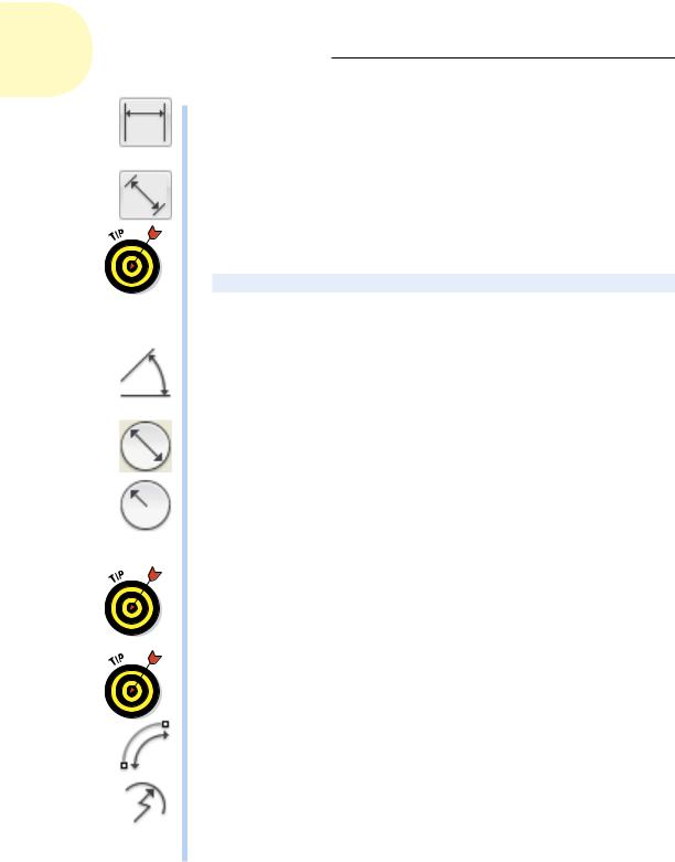
AutoCAD provides several types of dimensions and commands for drawing them; most commands are shown in Figure 14-2. These commands are found on the Dimensions panel of the Annotate tab of the Ribbon. If you can’t find the button you want, it’s probably hidden in the drop-down list under the larger button on the left side of this panel. This panel remembers the last button used, so at any given time, it may be displaying any one of the following buttons:
www.it-ebooks.info
302 Part III: If Drawings Could Talk
Linear: DIMLINear. Indicates the linear extent of an object or the linear distance between objects. Most linear dimensions are either horizontal or vertical, but you can draw dimensions that are rotated to other angles, too.
Aligned: DIMALIgned. Similar to linear dimensions, but the dimension line tilts to the same angle as a line drawn through the origin points of its extension lines.
You don’t always have to pick points when placing dimensions. Watch the Command window; it may ask you to
Specify first extension line origin or <select object>:
If you press Enter instead of picking the first point, AutoCAD will ask you to select an object. And when you do, it automatically selects each end of the object for you.
Angle: DIMANGle. Indicates the angular measurement between two lines, the two endpoints of an arc, or two points on a circle. The dimension line appears as an arc that indicates the sweep of the measured angle.
Radial: DIMDIAmeter, DIMRADius. This has nothing to do with AM or FM electromagnetic radiation. A radius dimension shows the radius of a circle or an arc, and a diameter dimension calls out the diameter of a circle or an arc. You can position the dimension text inside or outside the curve; refer to Figure 14-2. If you position the text outside the curve, AutoCAD (by default) draws a little cross at the center of the circle or arc. AutoCAD automatically adds the diameter and radius symbols to the appropriate dimension type.
If you’re wondering when you should use which (because radius and diameter dimensions seem to do the same thing), the convention in most drafting disciplines is to use diameter dimensions for whole circles (for example, a hole) and radius dimensions for part circles or arcs (for example, a fillet).
You can also use DIMLINear to dimension a circle or arc. Trying to pick the endpoints of a circle can keep you busy for several hours, but if you press Enter at the first prompt and then select an arc or circle, it will apply a linear dimension across the diameter.
Arc Lenth: DIMARC. Measures the length of an arc as though it were stretched out straight, and then applies a curved dimension line concentric with the arc.
Jog: DIMJOGGED. No, this has nothing to do with dimensioning your morning exercise run. Standard drafting practice when dimensioning arcs is to create a dimension line that starts at the center of the arc and proceeds outward to the arc itself. A problem arises, however, when dimensioning arcs with a very large radius. The center may be at an inconvenient location
www.it-ebooks.info
Chapter 14: Entering New Dimensions 303
where the dimension line would interfere with other geometry — or worse yet, may be well beyond the edge of the final drawing. DIMJOGGED neatly solves this problem for you. It works almost exactly like DIMARC except that it asks you to specify two extra points. After you select the arc (or circle, strangely enough), it then asks you to specify a center override point and then for a location for the jog itself. The resulting dimension line consists of three segments, starting at the center override point: The first and last point to the real center, and the middle segment connects the ends of the other two to put a jog in the line.
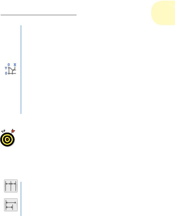
Ordinate: DIMORDinate applies X or Y coordinate dimensions from an origin point. Certain types of mechanical parts can have a great many holes and other features. The drawing would get impossibly cluttered if you were to apply two traditional dimensions to show the X and Y locations of each detail. Common practice in this situation is to use ordinate dimensioning. Each ordinate dimension appears simply as a single extension line and a number showing the X or Y distance from the origin of the drawing or from the origin of the current User Coordinate System (UCS) if there is one. We cover UCSs in Chapter 7. Normal practice is to specify the lower-left corner of the part to be the origin. The X and Y values are usually aligned neatly in a row and column along the edge of the part. There are no dimension lines or arrowheads.
These basic dimension commands are also found in the upper-right corner of the Annotation panel of the Home tab on the Ribbon.
Leaders used to be placed by using a command from the dimensioning set, but they are now much more powerful and versatile, and so are considered to be text annotations. We cover them in Chapter 13.
The lazy drafter jumps over to the quick dimension commands
Three dimensioning commands can help you place multiple dimensions very quickly. They are found on the right side of the Dimensions panel of the Annotate tab of the Ribbon.
Continue: DIMCONTinue. Having placed one linear dimension, you can now carry on to place a series of end-to-end dimensions. AutoCAD automatically picks the end of the previous dimension as the start of the next one, so you need to pick the end of only the next one.
Base: DIMBASEline. This works much like DIMCONTinue except that AutoCAD selects the start of the previous one as the start of the next one. You thus end up with a series of dimensions, all measuring from a common starting point.
www.it-ebooks.info
304 Part III: If Drawings Could Talk
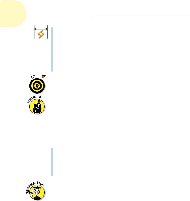
Quick Dimensions: QDIM. Interestingly, this is one of the very few dimensioning commands that doesn’t start with DIMxxx. When you invoke it, it invites you to select objects. The best bet usually is to use one or more Window selections (pick left to right), each of which completely surrounds several objects. Now, when you press Enter to continue, AutoCAD automatically applies DIMLINear dimensions wherever it can (and you might be surprised at some of those places!). It can place dimensions in several formats, including continue, baseline, staggered, ordinate, and several others. For convenience in repeat operations, it remembers the last mode you used.
If you want to be superefficient, memorize the three-letter keyboard aliases for the dimension commands you use the most. The aliases for the most common commands are shown in Figure 14-2.
The AutoCAD dimensioning commands prompt you with useful information at the command window or dynamic-input prompts. Read the prompts during every step of the command, especially when you’re trying a dimensioning command for the first time. When all else fails. . . .
Dimension associativity
By default, AutoCAD groups all the parts of each dimension — the extension lines, dimension lines, arrowheads, and text — into a special associative dimension object. Associative means two things:
The different parts of the dimension function as a single object. When you click any part of the dimension, AutoCAD selects all its parts.
The dimension is connected to the points on the object that you specified when you drew the dimension. If you change the size of the object (for example, stretch a line), the dimension updates appropriately. The lines and arrows move, and the text changes to reflect the line’s new size.
The associative dimensions we’re talking about here first appeared in AutoCAD 2002. Before that, AutoCAD had a more primitive kind of dimensioning. Dimensions were single objects, and they did update if you stretched an object if you were very careful to include the dimension itself in the crossing selection for the STRETCH command. Here’s where things can get a bit confusing: AutoCAD used to call these old-style, single-object dimensions associative but now calls them non-associative. And what used to be called non-associative dimensions before AutoCAD 2002 are now called exploded dimensions — but
if you Explode a dimension, you get four lines, two arrowheads, and a piece of text. Sometimes you can’t tell the players even with a program. For more
information about how to determine which kind of dimension AutoCAD draws, see the “Controlling and editing dimension associativity” section, later in
this chapter. We mention the old style here only because you will probably encounter it in old drawings.
www.it-ebooks.info