


|
|
Chapter 2: Le Tour de AutoCAD 2013 |
35 |
|
|
||
|
|
||
|
|
||
No Express service? |
|
||
If your Ribbon doesn’t include the Express Tools |
screen, make sure to select the Express Tools |
|
|
tab (at the far right in Figure 2-1), you should |
item in the list of components. If you don’t install |
|
|
consider installing the Express Tools from your |
the Express Tools during initial setup, you’ll have |
|
|
AutoCAD DVD. (AutoCAD LT does not include or |
to rerun the setup routine from your AutoCAD |
|
|
support the Express Tools.) |
DVD or USB stick. If you haven’t installed |
|
|
When you first install AutoCAD, you choose |
AutoCAD yet, we strongly recommend that |
|
|
you choose the Typical installation option — |
|
||
between a Typical and a Custom installation. |
|
||
or at least make sure that the Express Tools |
|
||
If you choose Typical, the next screen asks |
|
||
check box is selected checked during a Custom |
|
||
whether you want to install the Express Tools. |
|
||
installation. |
|
||
If you choose a Custom installation, in the next |
|
||
|
|
|
|
|
|
|
|
|
|
|
|
Express Tools: The Express Tools are an invaluable set of custom commands that streamline your work procedures in pretty well every aspect of AutoCAD. They’re officially unsupported, but they’ve been an install option for many releases now, and mostly, they work very well. You get this tab only if you have the full version of AutoCAD — Express Tools aren’t available in AutoCAD LT.
Other Ribbon tabs may exist if you purchased AutoCAD as part of a suite. AutoCAD suites are series of collections of related Autodesk products sold in one package under one serial number.
Getting with the Program
In most of this book, we focus on 2D drafting, which is by far the easiest way of getting your feet wet with AutoCAD. (Just don’t be dripping water on your computer.) And if you’re not already in the Drafting & Annotation workspace, we suggest that you use the Workspace Switching button to return to it.
After you make the switch to this workspace, AutoCAD displays the interface shown earlier in Figure 2-1.
Like all good Windows programs, AutoCAD has tooltips, those short descriptions that appear in little text boxes when you hover the mouse pointer over a button. In AutoCAD 2013, tooltips display two levels of information. When you hover the mouse pointer over a tool button, you first see a quick identification of the command. If you keep hovering, a longer description of the icon’s function, often with a graphic image, appears in an extended tooltip. Helpful as they are when you’re starting with AutoCAD, you’ll probably want to remove these training wheels sooner or later. You can do so in the Options dialog box. (See the online help for more information.)
www.it-ebooks.info
36 Part I: AutoCAD 101
Looking for Mr. Status Bar
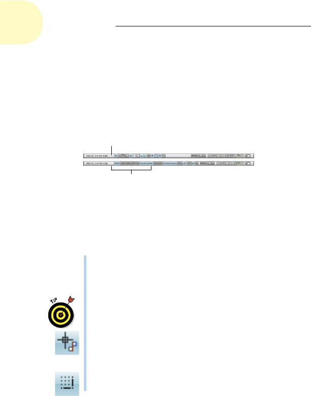
The application status bar (see Figure 2-6) appears at the bottom of the AutoCAD screen. The status bar displays and allows you to change several important drawing modes, aids, and settings that affect how you draw and edit in the current drawing. We introduce them in this section.
You can set status bar buttons to display icons or the traditional text labels that will be familiar to users of earlier releases. To switch from one style to the other, right-click any of the drawing mode buttons at the left side of the status bar and select or deselect Use Icons.
Status bar buttons showing icons
Status bar buttons showing text labels
Figure 2-6: Status (bars) check.
Some of these status bar settings won’t make complete sense until you’ve used the AutoCAD commands that they influence, but here’s a brief description, with references to detailed descriptions of how to use each setting, starting at the left end of the status bar (and note that not all buttons are displayed at all times, so Figure 2-6 doesn’t show all the buttons listed):
Coordinates of the crosshairs: The coordinates readout displays the current X,Y,Z location of the crosshairs in the drawing area, with respect to the origin point, whose coordinates are 0,0,0. (AutoCAD LT displays only the X,Y crosshairs location.) Chapter 7 describes AutoCAD’s coordinate conventions and how to use this area of the status bar.
If the coordinates in the lower-left corner of the screen are grayed out, coordinate tracking is turned off. Click the coordinates so that they appear in dark numbers that change when you move the crosshairs in the drawing area.
Infer Constraints (INFER): Parametric constraints were new in AutoCAD 2010. (The inferred constraints feature isn’t available in AutoCAD LT.) When Infer Constraints is enabled, you automatically set geometrybased constraints as you draw. We cover geometric and dimensional constraints in Chapter 19.
Snap Mode (SNAP): Constrains the crosshairs to regularly spaced intervals, enabling you to draw objects a fixed distance apart more easily.
www.it-ebooks.info
Chapter 2: Le Tour de AutoCAD 2013 |
37 |
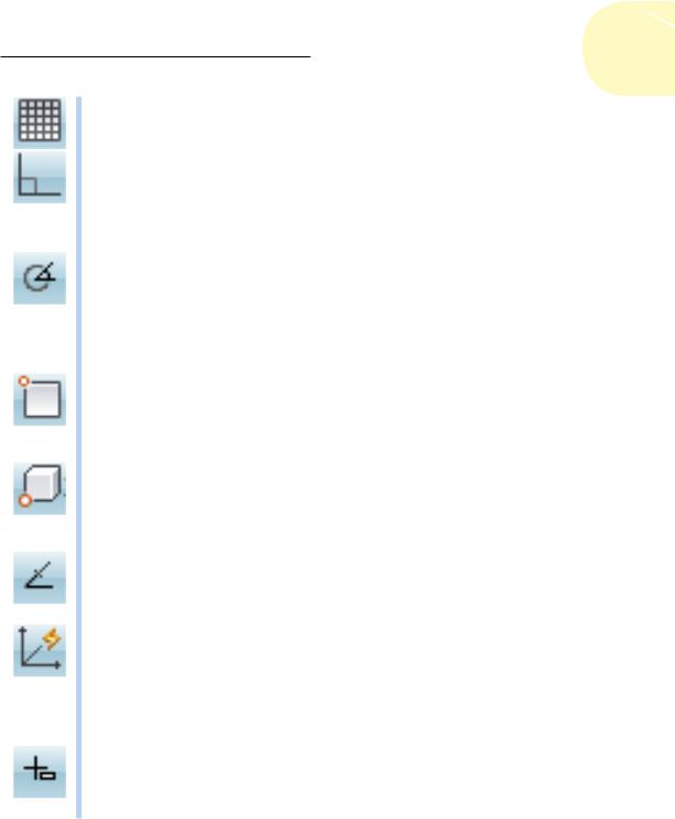
Grid Display (GRID): Displays a series of graph paper–style lines or regularly spaced dots, which serve as a distance reference.
Ortho Mode (ORTHO): Constrains the crosshairs to horizontal and vertical movement, which makes drawing orthogonal (straight horizontal and vertical) lines easy.
See Chapter 4 for instructions on how to configure these modes and Chapter 7 for information about why, when, and how to use them in actual drawing operations.
Polar Tracking (POLAR): Polar tracking causes the crosshairs to jump to certain angles when you draw and edit objects. The default angle settings are multiples of 90 degrees, but you can specify other angle increments, such as 45 or 30 degrees. See Chapter 7 for instructions on specifying the polar tracking angles that you prefer. Clicking the Polar button toggles polar tracking on and off. Ortho and polar tracking are mutually exclusive — turning on one mode disables the other.
Object Snap (OSNAP): Object snap is another AutoCAD tool for ensuring precision drawing and editing. You use object snaps to grab points on existing objects — for example, the endpoint of a line or the center of a circle. Chapter 7 contains detailed instructions on how to use this feature.
3D Object Snap (3DOSNAP): With AutoCAD’s enhanced 3D capabilities, an extension of object snaps into the third dimension was a given (not in AutoCAD LT, of course). Enabling this mode lets you snap to the precise center of a face, a vertex, the midpoint of an edge, or a number of similar 3D points you can’t get to with regular object snaps.
Object Snap Tracking (OTRACK): When you turn on object snap tracking, AutoCAD hunts in a more sophisticated way for points that are derived from object snap points. Chapter 7 briefly describes this advanced feature.
Allow/Disallow Dynamic UCS (DUCS): This one’s for 3D object creation (and so isn’t included in AutoCAD LT). Most AutoCAD primitive objects, such as lines, arcs, and circles, are planar, and you have to set an appropriate 2D plane in three dimensions if you want to work in 3D. You can set planes with the UCS command — we explain how in Chapter 22 — but enabling Dynamic UCS automatically sets the workplane by simply hovering the mouse over the face of an object.
Dynamic Input (DYN): Dynamic Input displays commands, options, prompts, and user input in a tooltip adjacent to the crosshairs and enables you to keep focused on what you’re drawing. In addition, the Dynamic Input tooltip displays what you type in response to prompts. We describe Dynamic Input later in this chapter.
www.it-ebooks.info
38 Part I: AutoCAD 101
Show/Hide Lineweight (LWT): One of the properties that you can assign to objects in AutoCAD is lineweight — the thickness that lines appear when you plot the drawing. This button controls whether you see the lineweights on the screen. (This button doesn’t control whether lineweights appear on plots; that’s a separate setting in the Plot dialog box.) Chapter 6 gives you the skinny (and the wide) on lineweights.
Show/Hide Transparency (TPY): You can assign transparency to individual objects or to all objects on a given layer. Similar to the Lineweight button, this button controls whether objects assigned the transparency property appear transparent or opaque. We introduce you to object transparency in Chapter 6.
Quick Properties (QP): When Quick Properties is enabled, selecting an object in the drawing displays a pop-up window that lists a selection of properties of that object. You can choose which properties you want displayed by right-clicking the QP button and choosing Settings. We fill you in on object properties in Chapter 6.
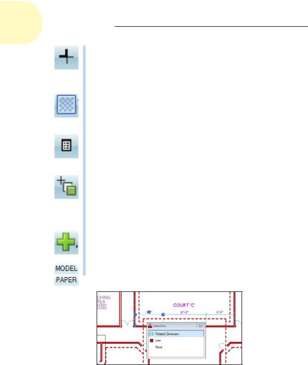
Selection Cycling (SC): It’s remarkably easy in AutoCAD to draw objects on top of other objects and not be able to tell you’ve done so. When Selection Cycling is enabled, an icon showing two overlapping rectangles appears beside the crosshairs if AutoCAD finds more than one object under them. If you then click to select, a Selection window pops up showing you how many objects, and of what type, are under the point that you picked (see Figure 2-7).
Annotation Monitor: When using associative annotations, such as dimensions, it’s possible for the link between the annotation and the object it’s annotating to get broken. When turned on, the Annotation Monitor warns you of this and highlights the offending objects.
Model or Paper Space (MODEL/PAPER): Clicking this button toggles between model space and paper space.
Figure 2-7: Overlapping objects listed in the Selection window.
www.it-ebooks.info
Chapter 2: Le Tour de AutoCAD 2013 |
39 |
As we describe in the upcoming section, “Down the main stretch: The drawing area,” AutoCAD’s drawing area is composed of two overlapping environments: Model space is where you create your model geometry, and paper space is where you compose your drawing sheet to document that geometry. Clicking this button when the Model tab is active (that is, you’re in full-screen model space) switches you to a paper space layout. A completed layout includes viewports, which reveal the objects in model space at a particular scale. (We tell you more about viewports and layouts in Chapter 5.) After you switch to a paper space layout, clicking this button toggles between paper space and model space within the layout. The button label switches from MODEL to PAPER to show you which space you’re in.
Model and <Layout>: These two buttons disappear if Model and Layout tabs are displayed. Clicking the Model button switches you out of the layout and back to full-screen model space. (If Model and Layout tabs are displayed, you click the Model tab to switch to full-screen model space.) Clicking Layout switches you to whichever paper space layout was active when you switched to model space. Also note that the tooltip for the Layout button displays the name of the layout, which might be changed from the default Layout1 or Layout2.
Quick View Layouts: Clicking this button displays a horizontal row of graphic images of all layouts in the current drawing. Click a layout image to make that layout current. The Quick View toolbar below the layout images contains buttons for pinning the Quick View Layouts bar so it stays open, creating a new layout, publishing the selected layout, and closing Quick View Layouts. We cover layout creation in Chapter 5 and publishing in Chapter 16.
Quick View Drawings: Clicking this button displays a row of graphic images of all open drawings. Click a drawing image to make it active. Quick View Drawings includes the same Quick View toolbar as Quick View Layouts. We cover this in Chapter 5.
Maximize/Minimize Viewport (appears on paper space layouts only):
When you’re looking at one of the Layout tabs instead of the Model tab, the status bar displays an additional Maximize Viewport button. Click this button to expand the current paper space viewport so that it fills the entire drawing area. Click the button — now called Minimize Viewport — again to restore the viewport to its normal size. (Chapter 5 describes viewports.)
The next group of buttons controls the size and appearance of AutoCAD’s annotative objects — things like text, dimensions, hatching, and so forth. Annotative objects appear to be complex, so don’t worry if you don’t understand at this point. For now, just remember that, in this chapter, we’re just showing you what the buttons do. Because annotative objects means text more than anything else, we explain this powerful feature that actually simplifies drawing processes in Chapter 13.
www.it-ebooks.info
40 Part I: AutoCAD 101
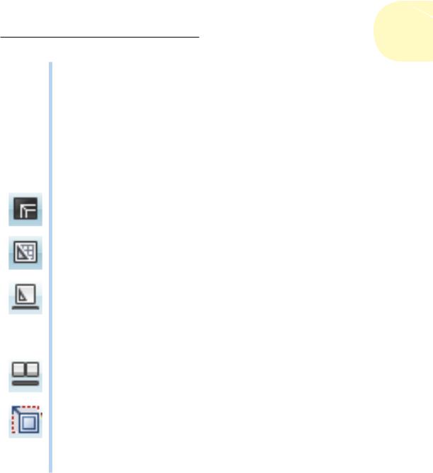
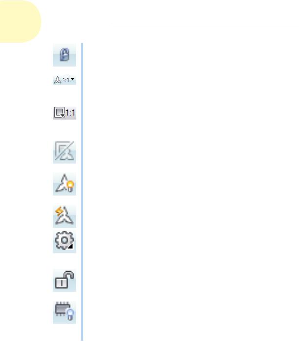
Lock/Unlock Viewport: When you’re satisfied with the display inside your viewport, and you’ve assigned a viewport scale, use this button to lock the viewport display so you don’t accidentally pan or zoom inside it. (See Chapter 5 for more on viewports.)
Annotation Scale (appears in full-screen model space only): Clicking Annotation Scale displays a list of preset annotation scales; if the Automatically Add Scales button is toggled on, changing a scale here causes all annotative objects to update to the new scale.
Viewport Scale: This button appears only in a layout, when a model space viewport is activated. If the viewport is locked, this button is inactive. If the viewport is unlocked, clicking the button displays a list of scales; choose the desired scale from the list.
Annotation Scale Is Not Equal To Viewport Scale: If the scale assigned to annotative objects within the viewport differs from the scale assigned to the viewport itself, clicking this button will synchronize the annotation scale to the viewport scale.
Annotation Visibility: This button toggles the visibility of annotative objects. When the light bulb is off (gray), only annotative objects of the current annotative scale are visible; when the light bulb is on (yellow), all annotative objects in the drawing, regardless of scale, are visible.
Automatically Add Scales: When this button is toggled on, additional annotative scales are automatically added to objects inside the viewport when you change the viewport scale.
Workspace Switching: Clicking this button displays a list of saved workspaces, including the four default workspaces (two in AutoCAD LT): AutoCAD Classic, Drafting & Annotation, 3D Basics, and 3D Modeling (the latter two aren’t included in AutoCAD LT), plus any user-defined and saved workspaces.
Lock/Unlock Toolbar/Window Positions: “Now, where did we leave that Properties palette?” You’ll never have to ask yourself that question again because you can click this button to lock the Ribbon, toolbars, or palettes in position, so you’ll always know where they are.
Hardware Acceleration: You can quickly toggle hardware acceleration on and off from the status bar. Prior to AutoCAD 2011, you had to run the 3DCONFIG command and proceed through a couple of dialog boxes. Visit the online help to find out more about improved graphics performance and better rendering options by using hardware acceleration; hardware acceleration is available in both AutoCAD and AutoCAD LT.
The remaining status bar icons, with the exception of Clean Screen at the very end, live in a special area of the status bar called the tray. The tray displays icons that represent drawing services, and most do not appear at all times. These tray icons include
www.it-ebooks.info
Chapter 2: Le Tour de AutoCAD 2013 |
41 |
Trusted Autodesk DWG: A trusted drawing is one created by AutoCAD, AutoCAD LT, or any program developed by Autodesk. In recent years, more and more programs have been able to save in DWG format, but in Autodesk’s eyes, these files are not to be trusted. If you open such a drawing file, you’ll get a warning dialog box and a little yellow danger sign over the trusted DWG icon (make sure that you know where your wallet is when you work on one of these files).
Object Isolation: You don’t need to turn a layer — and everything on it — off if you want a clearer view of something in a crowded drawing. Now you can select an object and either hide it (so it disappears) or isolate it (so everything else disappears). If the light bulb on this button is dim, one or more objects are either hidden or isolated; click the button and choose Unisolate Objects to turn everything else — including the light bulb icon — back on.
Associated Standards File: You see this button if you’ve enabled CAD standards-checking and configured a drawing standards (DWS) file. Clicking this button displays the Check Standards dialog box. AutoCAD’s CAD Standards functions are not included in AutoCAD LT. We don’t cover standards-checking in this book.
Manage Xrefs: You won’t see this combination button and notification symbol until you open a drawing that contains xrefs (external DWG files that are incorporated into the current drawing). Chapter 18 tells you how to use xrefs and what the Manage Xrefs button does.
Status Bar Menu: When you click the easy-to-miss, downward-pointing arrow near the right end of the status bar, you open a menu with options for toggling off or on each status bar button. Now you can decorate your status bar to your taste. You can also turn on the drawing status bar. Doing so moves any of these tray icons and the three annotation scaling buttons described earlier to a separate drawing-specific status bar. (My personal preference is to leave it turned off.)
Clean Screen: No, this button doesn’t squeegee your monitor. Clicking this button frees up a bit more screen space by first maximizing the AutoCAD window and then turning off the title bar, toolbars, palettes, and the Windows taskbar. Click the button again to restore those elements.
Several status bar buttons, including Snap Mode, Polar Tracking, Object Snap, and Object Snap Tracking, sport right-click menus that offer a speedier way of setting options. With some of the other buttons, such as Grid Display and Dynamic Input, you right-click the button and choose Settings to open the Drafting Settings dialog box to specify options. Chapters 4 and 6 give you specific guidance about when and how to change these settings.
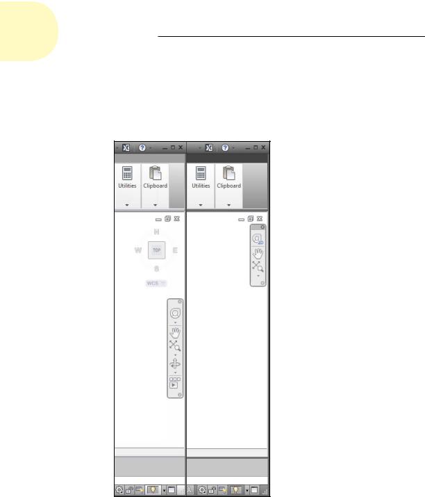
In AutoCAD 2013, primary access to the display commands is via the Navigation bar that appears, by default, at the right edge of the program window. AutoCAD also has a ViewCube that provides an alternative to the
www.it-ebooks.info
42 Part I: AutoCAD 101
Orbit tool. (Neither the ViewCube nor the Orbit tool are included in AutoCAD LT.) Figure 2-8 shows the differences between the navigation devices in AutoCAD (on the left) and AutoCAD LT. We introduce you to the Navigation bar buttons in the following list, and explain their operation more fully in Chapter 12. We give you the drill on the ViewCube and the Orbit tool in Chapter 21.
Figure 2-8: Navigation tools in AutoCAD (left) and AutoCAD LT (right).
www.it-ebooks.info