

- •About the Authors
- •Dedication
- •Authors’ Acknowledgments
- •Table of Contents
- •Introduction
- •What’s Not (And What Is) in This Book
- •Mac attack!
- •Who Do We Think You Are?
- •How This Book Is Organized
- •Part I: AutoCAD 101
- •Part II: Let There Be Lines
- •Part III: If Drawings Could Talk
- •Part IV: Advancing with AutoCAD
- •Part V: On a 3D Spree
- •Part VI: The Part of Tens
- •But wait . . . there’s more!
- •Icons Used in This Book
- •A Few Conventions — Just in Case
- •Commanding from the keyboard
- •Tying things up with the Ribbon
- •Where to Go from Here
- •Why AutoCAD?
- •The Importance of Being DWG
- •Seeing the LT
- •Checking System Requirements
- •Suddenly, It’s 2013!
- •AutoCAD Does Windows (And Office)
- •And They’re Off: AutoCAD’s Opening Screens
- •Running with Ribbons
- •Getting with the Program
- •Looking for Mr. Status Bar
- •Let your fingers do the talking: The command window
- •The key(board) to AutoCAD success
- •Keeping tabs on palettes
- •Down the main stretch: The drawing area
- •Fun with F1
- •A Simple Setup
- •Drawing a (Base) Plate
- •Drawing rectangles on the right layers
- •Circling your plate
- •Nuts to you
- •Getting a Closer Look with Zoom and Pan
- •Modifying to Make It Merrier
- •Hip-hip-array!
- •Stretching out
- •Crossing your hatches
- •Following the Plot
- •A Setup Roadmap
- •Choosing your units
- •Weighing up your scales
- •Thinking annotatively
- •Thinking about paper
- •Defending your border
- •A Template for Success
- •Making the Most of Model Space
- •Setting your units
- •Making the drawing area snap-py (and grid-dy)
- •Setting linetype and dimension scales
- •Entering drawing properties
- •Making Templates Your Own
- •Setting Up a Layout in Paper Space
- •Will that be tabs or buttons?
- •View layouts Quick(View)ly
- •Creating a layout
- •Copying and changing layouts
- •Lost in paper space
- •Spaced out
- •A view(port) for drawing in
- •About Paper Space Layouts and Plotting
- •Managing Your Properties
- •Layer one on me!
- •Accumulating properties
- •Creating new layers
- •Manipulating layers
- •Using Named Objects
- •Using AutoCAD DesignCenter
- •Copying layers between drawings
- •Controlling Your Precision
- •Keyboard capers: Coordinate input
- •Understanding AutoCAD’s coordinate systems
- •Grab an object and make it snappy
- •Other Practical Precision Procedures
- •Introducing the AutoCAD Drawing Commands
- •The Straight and Narrow: Lines, Polylines, and Polygons
- •Toeing the line
- •Connecting the lines with polyline
- •Squaring off with rectangles
- •Choosing your sides with polygon
- •(Throwing) Curves
- •Going full circle
- •Arc-y-ology
- •Solar ellipses
- •Splines: The sketchy, sinuous curves
- •Donuts: The circles with a difference
- •Revision clouds on the horizon
- •Scoring Points
- •Commanding and Selecting
- •Command-first editing
- •Selection-first editing
- •Direct object manipulation
- •Choosing an editing style
- •Grab It
- •One-by-one selection
- •Selection boxes left and right
- •Perfecting Selecting
- •AutoCAD Groupies
- •Object Selection: Now You See It . . .
- •Get a Grip
- •About grips
- •A gripping example
- •Move it!
- •Copy, or a kinder, gentler Move
- •A warm-up stretch
- •Your AutoCAD Toolkit
- •The Big Three: Move, Copy, and Stretch
- •Base points and displacements
- •Move
- •Copy
- •Copy between drawings
- •Stretch
- •More Manipulations
- •Mirror
- •Rotate
- •Scale
- •Array
- •Offset
- •Slicing, Dicing, and Splicing
- •Trim and Extend
- •Break
- •Fillet and Chamfer and Blend
- •Join
- •When Editing Goes Bad
- •Zoom and Pan with Glass and Hand
- •The wheel deal
- •Navigating your drawing
- •Controlling your cube
- •Time to zoom
- •A View by Any Other Name . . .
- •Looking Around in Layout Land
- •Degenerating and Regenerating
- •Getting Ready to Write
- •Simply stylish text
- •Taking your text to new heights
- •One line or two?
- •Your text will be justified
- •Using the Same Old Line
- •Turning On Your Annotative Objects
- •Saying More in Multiline Text
- •Making it with Mtext
- •It slices; it dices . . .
- •Doing a number on your Mtext lists
- •Line up in columns — now!
- •Modifying Mtext
- •Gather Round the Tables
- •Tables have style, too
- •Creating and editing tables
- •Take Me to Your Leader
- •Electing a leader
- •Multi options for multileaders
- •How Do You Measure Up?
- •A Field Guide to Dimensions
- •The lazy drafter jumps over to the quick dimension commands
- •Dimension associativity
- •Where, oh where, do my dimensions go?
- •The Latest Styles in Dimensioning
- •Creating and managing dimension styles
- •Let’s get stylish!
- •Adjusting style settings
- •Size Matters
- •Details at other scales
- •Editing Dimensions
- •Editing dimension geometry
- •Editing dimension text
- •Controlling and editing dimension associativity
- •Batten Down the Hatches!
- •Don’t Count Your Hatches. . .
- •Size Matters!
- •We can do this the hard way. . .
- •. . . or we can do this the easy way
- •Annotative versus non-annotative
- •Pushing the Boundary (Of) Hatch
- •Your hatching has no style!
- •Hatch from scratch
- •Editing Hatch Objects
- •You Say Printing, We Say Plotting
- •The Plot Quickens
- •Plotting success in 16 steps
- •Get with the system
- •Configure it out
- •Preview one, two
- •Instead of fit, scale it
- •Plotting the Layout of the Land
- •Plotting Lineweights and Colors
- •Plotting with style
- •Plotting through thick and thin
- •Plotting in color
- •It’s a (Page) Setup!
- •Continuing the Plot Dialog
- •The Plot Sickens
- •Rocking with Blocks
- •Creating Block Definitions
- •Inserting Blocks
- •Attributes: Fill-in-the-Blank Blocks
- •Creating attribute definitions
- •Defining blocks that contain attribute definitions
- •Inserting blocks that contain attribute definitions
- •Edit attribute values
- •Extracting data
- •Exploding Blocks
- •Purging Unused Block Definitions
- •Arraying Associatively
- •Comparing the old and new ARRAY commands
- •Hip, hip, array!
- •Associatively editing
- •Going External
- •Becoming attached to your xrefs
- •Layer-palooza
- •Creating and editing an external reference file
- •Forging an xref path
- •Managing xrefs
- •Blocks, Xrefs, and Drawing Organization
- •Mastering the Raster
- •Attaching a raster image
- •Maintaining your image
- •Theme and Variations: Dynamic Blocks
- •Lights! Parameters!! Actions!!!
- •Manipulating dynamic blocks
- •Maintaining Design Intent
- •Defining terms
- •Forget about drawing with precision!
- •Constrain yourself
- •Understanding Geometric Constraints
- •Applying a little more constraint
- •AutoConstrain yourself!
- •Understanding Dimensional Constraints
- •Practice a little constraint
- •Making your drawing even smarter
- •Using the Parameters Manager
- •Dimensions or constraints — have it both ways!
- •The Internet and AutoCAD: An Overview
- •You send me
- •Send it with eTransmit
- •Rapid eTransmit
- •Bad reception?
- •Help from the Reference Manager
- •Design Web Format — Not Just for the Web
- •All about DWF and DWFx
- •Autodesk Design Review 2013
- •The Drawing Protection Racket
- •Autodesk Weather Forecast: Increasing Cloud
- •Working Solidly in the Cloud
- •Free AutoCAD!
- •Going once, going twice, going 123D
- •Your head planted firmly in the cloud
- •The pros
- •The cons
- •Cloudy with a shower of DWGs
- •AutoCAD 2013 cloud connectivity
- •Tomorrow’s Forecast
- •Understanding 3D Digital Models
- •Tools of the Trade
- •Warp speed ahead
- •Entering the third dimension
- •Untying the Ribbon and opening some palettes
- •Modeling from Above
- •Using 3D coordinate input
- •Using point filters
- •Object snaps and object snap tracking
- •Changing Planes
- •Displaying the UCS icon
- •Adjusting the UCS
- •Navigating the 3D Waters
- •Orbit à go-go
- •Taking a spin around the cube
- •Grabbing the SteeringWheels
- •Visualizing 3D Objects
- •Getting Your 3D Bearings
- •Creating a better 3D template
- •Seeing the world from new viewpoints
- •From Drawing to Modeling in 3D
- •Drawing basic 3D objects
- •Gaining a solid foundation
- •Drawing solid primitives
- •Adding the Third Dimension to 2D Objects
- •Creating 3D objects from 2D drawings
- •Modifying 3D Objects
- •Selecting subobjects
- •Working with gizmos
- •More 3D variants of 2D commands
- •Editing solids
- •Get the 2D Out of Here!
- •A different point of view
- •But wait! There’s more!
- •But wait! There’s less!
- •Do You See What I See?
- •Visualizing the Digital World
- •Adding Lighting
- •Default lighting
- •User-defined lights
- •Sunlight
- •Creating and Applying Materials
- •Defining a Background
- •Rendering a 3D Model
- •Autodesk Feedback Community
- •Autodesk Discussion Groups
- •Autodesk’s Own Bloggers
- •Autodesk University
- •The Autodesk Channel on YouTube
- •The World Wide (CAD) Web
- •Your Local ATC
- •Your Local User Group
- •AUGI
- •Books
- •Price
- •3D Abilities
- •Customization Options
- •Network Licensing
- •Express Tools
- •Parametrics
- •Standards Checking
- •Data Extraction
- •MLINE versus DLINE
- •Profiles
- •Reference Manager
- •And The Good News Is . . .
- •APERTURE
- •DIMASSOC
- •MENUBAR
- •MIRRTEXT
- •OSNAPZ
- •PICKBOX
- •REMEMBERFOLDERS
- •ROLLOVERTIPS
- •TOOLTIPS
- •VISRETAIN
- •And the Bonus Round
- •Index
Chapter 19: Call the Parametrics! 439
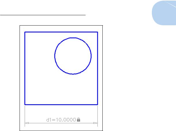
Figure 19-9: Placing a dimensional constraint.
Making your drawing even smarter
If this were a traditional mechanical drawing that followed the rules of drafting, those two dimensions would be enough: Whoever is reading your drawing understands that if sides are parallel and perpendicular, a dimension on one side applies to the opposite side as well. But in this chapter, we’re talking about intelligent drawings that respect design intent, not dumb collections of lines and circles, even if they do follow the rules of drafting!
If you try stretching the rectangle in various ways (from the upper-left corner, for example), you can see that only the bottom and right sides are constrained to 10 units in length. You could add two more linear dimensional constraints to the unconstrained sides, but then you’d have to remember to edit both dimensions. Rather than constraining both sides to be 10 units long, the way to maintain design intent is to make both sides equal in length.
www.it-ebooks.info
440 Part IV: Advancing with AutoCAD
You can make the two sides equal by using either dimensional or geometric constraints. It’s usually a good idea to apply most or all of the geometric constraints to your drawing before adding dimensional constraints. This way, the objects will behave in a more predictable manner when you change dimension values.
We cover geometric constraints in the “Understanding Geometric Constraints” section, earlier in the chapter, so if you read that section, you should understand why we’re going to apply three geometric constraints.
1.On the Geometric panel of the Parametric tab, click Fix (the padlock icon) and then click the lower-left corner of the rectangle.
2.On the Geometric panel, click Horizontal and then click the bottom side of the rectangle. Then click Vertical and click the left side.
Icons appear near the drawing geometry, showing that those three geometric constraints are active.
3.On the Dimensional panel of the Parametric tab, click Linear and add a dimensional constraint to the top horizontal line.
4.Click to locate the dimension, type d1, and then press Enter when
AutoCAD prompts for the dimension text.
Instead of having numeric values like the first two linear constraints, this new dimensional constraint displays fx: d3=d1.
The main part of this expression sets the d3 dimension to equal the value of the d1 dimension. The fx: is there just to remind you that other variables in other dimensions are being referenced.
5.Repeat Steps 3 and 4, this time adding a constraint to the vertical line at the left and then entering d2 as the dimension text.
All four dynamic dimensional constraints display their names, plus a value or expression for each.
Dimensional constraints have names as well as values. They can also include expressions or formulas. You can set the default appearance of dynamic dimensional constraints by clicking the dialog-box launcher (the little arrow at the right end of the Dimensional panel label) to open the Constraint Settings dialog box with the Dimensional tab active (see Figure 19-10). The options are
Name: The first linear dimension is named d1, the second d2, and so forth. You use the dimension names in expressions.
Value: The numeric value that you enter into the dimensional constraint or that AutoCAD enters if you don’t override it.
www.it-ebooks.info
Chapter 19: Call the Parametrics! 441
Name and Expression: The dimension name shown as equal to an expression. The expression can be a value, as in this example, or it can be a formula.
Figure 19-10: Format the appearance of dimensional constraints in the Constraint Settings dialog box.
Using the Parameters Manager
Both AutoCAD and AutoCAD LT include the Parameters Manager palette, accessible from the Manage panels of their Ribbon’s Parametric tab. You can use the Parameters Manager to give all those dimensional constraints more sensible names than d1 and d2, but even more usefully, you can enter expressions instead of plain numeric values, as we explain in the following steps.
1.Click Parameters Manager in the Manage panel.
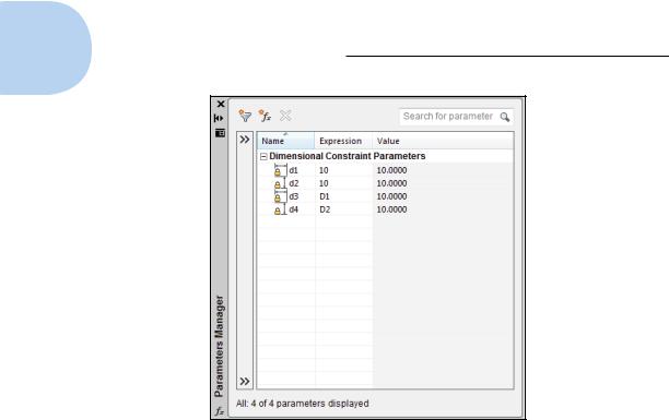
The Parameters Manager palette appears, showing a list of dimensional constraints currently applied in the drawing (see Figure 19-11).
In Figure 19-11, the Expression column shows the numeric values we specified for d1 and d2 and the expressions we entered for d3 and d4. The read-only Value column shows the calculated value. You can’t change a value in the Value column (it’s grayed out to remind you); you can only edit the cells in the Expression column.
www.it-ebooks.info
442 Part IV: Advancing with AutoCAD
Figure 19-11: The Parameters Manager palette.
2.In the d1 row, click in the Expression field to highlight the current
value (10 in this example); then click again and type a new value. For example, type 13 and press Enter.
The rectangle resizes itself in the drawing editor, and because the d3 constraint on the top side was made equal to the d1 constraint on the bottom side, both sides change equally.
Next, use an equation as an expression.
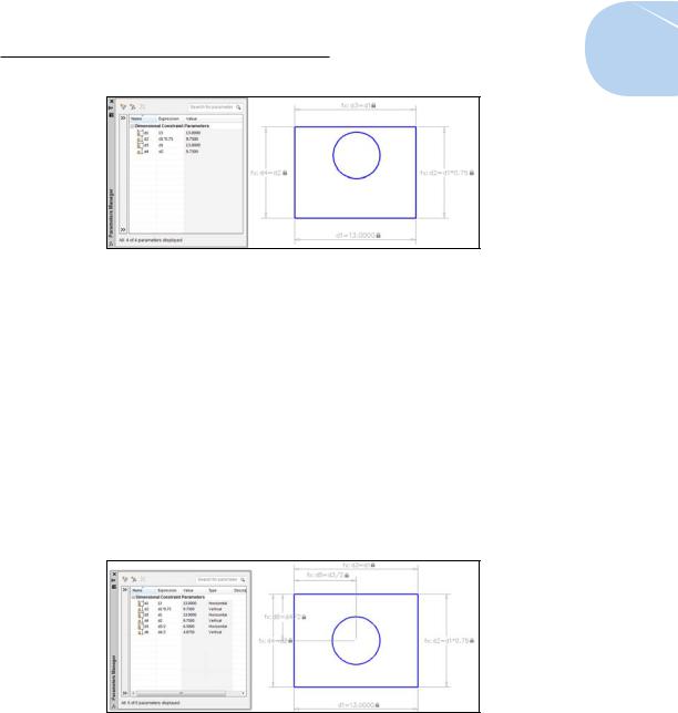
3.In the d2 row, click in the Expression field to highlight the current value and then type an expression. For example, type d1*0.75 and then press Enter.
The read-only Value column and the drawing geometry show that the new d1 distance of 13 has been multiplied by 0.75 and is now 9.75 (see Figure 19-12).
4.Close the Parameters Manager.
Finally, constrain the circle so that its center is always at dead center of the rectangle, no matter how the rectangle’s size changes.
www.it-ebooks.info
Chapter 19: Call the Parametrics! 443
Figure 19-12: Editing constraints in the Parameters Manager.
5.Apply a horizontal dimensional constraint from the upper-left corner
of the rectangle to the center of the circle. Locate the dimension, type d3/2, and then press Enter.
Because the rectangle is now dimensionally constrained on all four sides, it doesn’t really matter which corner you start from. And note that you don’t have to type the whole expression d5=d3/2. AutoCAD knows what you mean!
6.Repeat Step 5, this time adding a vertical constraint from one of the
corners to the center of the circle. Locate the dimension and then type d4/2.
Figure 19-13 shows the object geometry with all constraints added in this section. Who knew that drafting could be such fun?
Figure 19-13: All locked down — dimensionally, at least.
If your drawing starts getting overwhelmed with parameters, you can add parameter filters in the Parameters Manager palette. Right-click any parameter and choose Show Filter Tree, or click the double-right arrow at the top left
www.it-ebooks.info