

132 Part II: Let There Be Lines
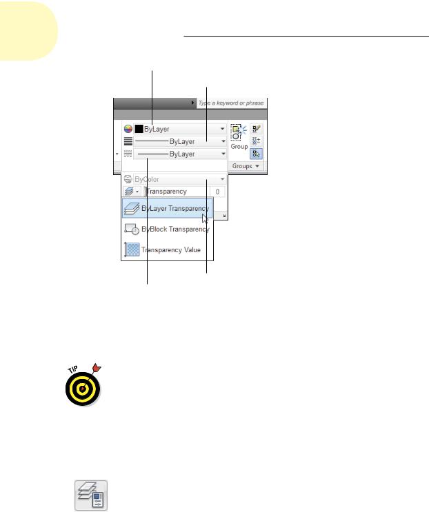
Color control
Lineweight control
Plot Style control
Linetype control
Figure 6-5: ByLayer (nearly) all the way.
If you prefer to do things the right way (that is, our way!), assign these properties ByLayer, as we describe in the following section.
AutoCAD’s SETBYLAYER command lets you correct those non-ByLayer properties — on the Ribbon’s Home tab, click the Modify panel label to open the panel slideout, and then click Set to ByLayer. Answer the prompts at the command line to finish modifying objects. For more information, refer to SETBYLAYER in the online help.
Creating new layers
If a suitable layer doesn’t exist, you need to create one in the Layer Properties Manager palette. Follow these steps:
1.Click the Layer Properties button on the Layers panel of the Ribbon’s Home tab, or type LAYER (or LA) at the command line and press Enter.
The Layer Properties Manager palette appears. A new drawing has only one layer: Layer 0. You need to add the layers necessary for your drawing.
2.Click the New Layer button (it looks like a sheet of paper with a little sunburst on one corner) to create a new layer.
www.it-ebooks.info
Chapter 6: Manage Your Properties 133
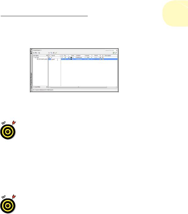
A new layer appears. AutoCAD names it Layer1 but highlights the name in an edit box so you can type a new name to replace it easily, as shown in Figure 6-6.
Figure 6-6: Adding a new layer in the Layer Properties
Manager palette.
3.Type a name for the new layer.
Type the layer name with initial caps (only the first letter of each word
in uppercase). Layer names written completely in uppercase are much wider, which means that they often get truncated in the Layer Control drop-down list.
Layer names should be descriptive and organized so they’re easily identifiable and sort logically. For example, names like Floor 01 plan, Floor 01 walls, Floor 01 electrical, Floor 02 plan, and so on are better than a drawing we saw recently that had 132 layers named with this sequence: 001,
002, 003, 004, . . .
4.On the same line as the new layer, click the color block or color name (White by default) of the new layer.
The Select Color dialog box appears, as shown in Figure 6-7.
The normal AutoCAD color scheme — AutoCAD Color Index (ACI) — provides 255 colors. So many choices are overkill for ordinary drafting.
For now, stick with the first nine colors — the ones that appear in a single, separate row to the left of the ByLayer and ByBlock buttons on the Index Color tab of the Select Color dialog box — for the following reasons:
•These colors are easy to distinguish from one another.
•Using a small number of colors makes configuring your plot param- eters easier. (We describe that procedure in Chapter 16.)
www.it-ebooks.info
134 Part II: Let There Be Lines
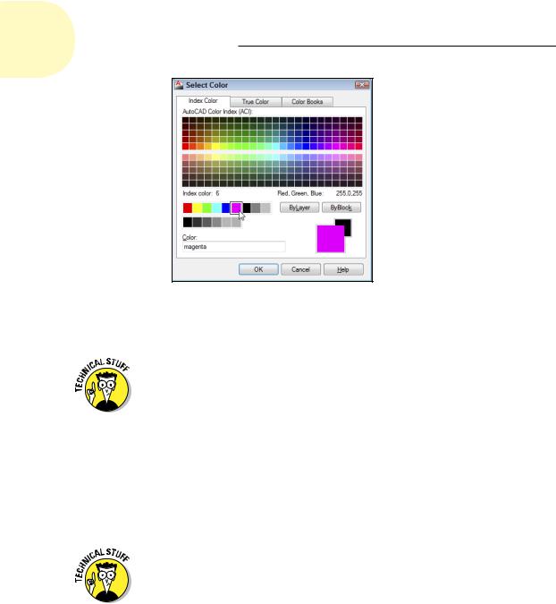
Figure 6-7: The Select Color dialog box.
Magenta is selected from the Standard
Colors list.
In the Select Color dialog box, the True Color tab offers a choice of more than 16 million colors, which you can specify by using HSL (hue, saturation, and luminance) or RGB (red, green, and blue) numbers. The Color Books tab enables you to use PANTONE, DIC, and RAL color schemes, which are popular in publishing. If your work requires tons of colors or close color matching between the computer screen and printed output, you’re probably familiar with the relevant color palette and how to use it. If you’re using AutoCAD for ordinary drafting or design, stick with the AutoCAD Color Index palette.
5.Click a color to select it as the color for this layer and click OK.
The Select Color dialog box closes, and focus returns to the Layer Properties Manager palette. In the Color column, the new layer color changes to either the name or the number of the color that you selected.
AutoCAD’s first seven colors have both numbers and standard names: 1 = red, 2 = yellow, 3 = green, 4 = cyan, 5 = blue, 6 = magenta, and 7 = white (which appears black when displayed on a white background). The remaining 248 colors have numbers only.
6.On the same line as the new layer, click the Linetype name of the new layer.
The Select Linetype dialog box appears, as shown in Figure 6-8.
The default AutoCAD linetype is Continuous, which means no gaps in the line.
www.it-ebooks.info

Chapter 6: Manage Your Properties 135
Figure 6-8: The Select Linetype dialog box.
If you already loaded the linetypes you need for your drawing, or if the template file you started from has some linetypes loaded, the Select Linetype dialog box displays them in the Loaded Linetypes list. If not, click the Load button to open the Load or Reload Linetypes dialog box. By default, AutoCAD displays linetypes from the standard AutoCAD
or AutoCAD LT linetype definition file — acad.lin for imperial-units drawings or acadiso.lin for metric-units drawings (acadlt.lin and acadltiso.lin in AutoCAD LT). Load the desired linetype by selecting its name and clicking OK.
Unless you have a really good reason (for example, your boss tells you so), avoid loading or using any linetypes labeled ACAD_ISO. These linetypes are normally used only in metric drawings — and rarely even then. They overrule everything we’re trying to show you about printed lineweight in what follows, so if at all possible, just say NO to ACAD_ISO. We promise you’ll find it easier to use the linetypes with the more descriptive names: CENTER, DASHED, and so on.
7.Click the desired linetype in the Loaded Linetypes list to select it as the linetype for the layer; say that really fast five times and then click OK.
The Select Linetype dialog box disappears, returning you to the Layer Properties Manager palette. In the Name list, the linetype for the selected layer changes to the linetype you just chose.
8.On the same line as the new layer, click the new layer’s lineweight.
The Lineweight dialog box appears, as shown in Figure 6-9.
www.it-ebooks.info
136 Part II: Let There Be Lines
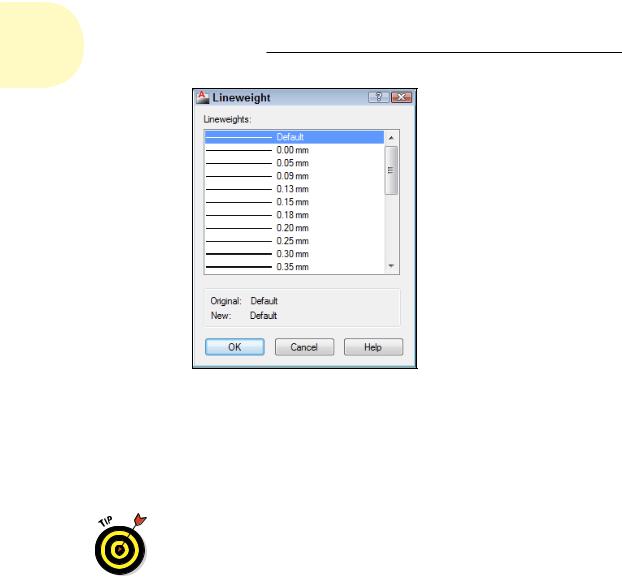
Figure 6-9: The Lineweight dialog box.
9.Select the lineweight you want from the list and click OK.
Using the lineweight property is a two-step process. After you’ve assigned a lineweight to a layer, you must click the Show/Hide Lineweight (LWT) button on the status bar to see the effect. You can turn the feature off and on with this button.
The lineweight 0.00mm tells AutoCAD to use the thinnest possible lineweight on the screen and on the plot. We recommend that for now, you leave lineweight set to Default, and instead later map screen colors to plotted lineweights, as described in greater detail in Chapter 16.
10.In the same line as the new layer, click the value in the Transparency column.
AutoCAD’s transparency property will probably be most appreciated by people preparing drawings for presentation. Clicking in the
Transparency column opens the Layer Transparency dialog box; type a numeric value between 0 and 90 or use the drop-down list to set a value. Transparency = 0 is the default, and means no transparency at all — objects drawn on a layer set to Transparency = 0 are completely opaque. Set the value to greater than 0 and you start seeing things through the objects you draw.
Similar to the Lineweight property, you have to turn on the Transparency (TPY) button on the status bar to see through your objects.
www.it-ebooks.info
Chapter 6: Manage Your Properties 137
11.Set the plot style for the new layer.
The Plot Style column’s contents depend on whether the drawing uses named plot styles or the traditional color-based plotting. Drawings set up to use color-based plotting display an unchangeable plot style name based on the layer’s color property. The grayed-out style name changes only when the layer color changes. If, on the other hand, your drawing uses named plot styles, you can assign a named plot style to the layer in this column. (Chapter 16 explains why you might not want to.)
12.Turn plotting on and off.
The setting in the Plot column controls whether the layer’s objects appear on plots. Click the little printer icon to turn off this setting (the little printer gets a red bar through it) for any layer whose objects you want to see on the screen but hide on plots. Layout viewports, covered in Chapter 5, are a good use for this feature.
13.(Optional) If you want to add a description to the layer, scroll the layer list to the right to see the Description column, click in the Description box corresponding to your new layer, and type a description.
As indicated in Step 2, our advice is to name your layers so you can tell what’s on them. If you do choose to use layer descriptions, stretch the Layer Properties Manager palette to the right so that you can see the descriptions without having to scroll the layer list.
14.Repeat Steps 1 through 13 to create any other layers that you want.
15.Select the new layer that you want to make current and click the Set Current button (the green check mark).
Changes you make in the Layer Properties Manager palette are instantaneous, unlike a dialog box in which you have to click OK to close the dialog box and apply the change.
Don’t forget to toggle on the Lineweight and Transparency buttons on the status bar to see the effect of assigning these properties. Unlike color and linetype, lineweight and transparency can be switched off and on.
The Layer Control drop-down list now displays your new layer as the current layer — the one on which AutoCAD places new objects that you draw.
After you create layers, you can set any one of them to be the current layer: Make sure that no objects are selected, and then choose the layer name from the Layer Control drop-down list on the Layers panel in the Ribbon or the Layers toolbar.
www.it-ebooks.info