

Chapter 11: Edit for Credit 233
If you want to offset a series of connected lines (for example, a rectangular house plan outline or one side of a pathway on a map), make sure that you either draw it as a polyline or convert the individual line and/or arc segments into a polyline with the JOIN command. (We cover JOIN later in this chapter.) If you draw a series of line segments with the LINE command and then try to offset it, you have to pick each segment and offset it individually. Even worse, the corners usually aren’t finished off in the way that you’d expect because AutoCAD doesn’t treat the segments as connected. You avoid all these problems by offsetting a polyline, which AutoCAD does treat as a single object. Figure 11-6 shows an offset polyline. See Chapter 8 for more information about the differences between lines and polylines.
Slicing, Dicing, and Splicing
The commands in this section — TRIM, EXTEND, BREAK, FILLET, CHAMFER, BLEND, and JOIN — are useful for shortening and lengthening objects, for breaking them in two, and for putting them back together again.
Trim and Extend
TRIM and EXTEND are the twin commands for making lines, polylines, and arcs shorter and longer. They’re the yin and yang, the Laurel and Hardy, the Jack Sprat and his wife of the AutoCAD editing world. The two commands and their prompts are almost identical, so the following steps cover both. We show the prompts for the TRIM command; the EXTEND prompts are similar.
1. Click the Trim or Extend button on the Home tab’s Modify panel.
AutoCAD prompts you to select cutting edges that will do the trimming (or, if you choose the EXTEND command, boundary edges for extending to):
Current settings: Projection=UCS, Edge=None
Select cutting edges ...
Select objects or <select all>:
2.Press Enter to accept the default option to select all drawing objects, or select individual objects by picking them. Press Enter to end object selection.
The objects you select in this step become the cutting edge of the TRIM command or the boundary to which objects will be extended by the EXTEND command.
Figure 11-7 shows a cutting edge (for TRIM) and a boundary edge (for EXTEND).
www.it-ebooks.info
234 Part II: Let There Be Lines
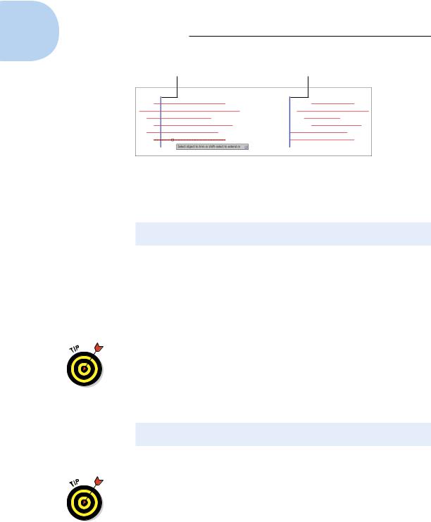
Cutting edge (for trim) Boundary edge (for extend)
Figure 11-7: Anatomy of the TRIM and EXTEND operations.
AutoCAD prompts you to select objects that you want to trim or extend (EXTEND doesn’t have the eRase option):
Select object to trim or shift-select to extend or [Fence/Crossing/Project/Edge/eRase/Undo]:
3.Select a single object to trim or extend. Choose the portion of the object that you want AutoCAD to trim away or the end of the object that’s closer to the extend-to boundary.
AutoCAD trims or extends the object to one of the objects that you selected in Step 2. If AutoCAD can’t trim or extend the object — for example, if the trimming object and the object to be trimmed are parallel — the command line displays an error message such as
Object does not intersect an edge.
You can select multiple objects to trim and extend by typing F and pressing Enter to use the Fence object selection mode or by entering C to use Crossing selection. Even better, you can use implied windowing and drag a selection box to select multiple objects. Refer to Chapter 10 for more on multiple object selection.
The command line continues to prompt you to select other objects to trim or extend:
Select object to trim or shift-select to extend or [Fence/Crossing/Project/Edge/eRase/Undo]:
4.Choose additional objects or press Enter when you’re finished trimming or extending.
Here’s a triple-threat tip: If you accidentally trim or extend the wrong object and you’re still in the TRIM or EXTEND command, type U and press Enter to undo the most recent trim or extend. You can switch between TRIM and EXTEND without exiting the command by holding down the Shift key. And finally, if you find yourself with a remnant that won’t trim because it doesn’t cross the cutting edge, type R (for eRase) and press Enter to erase it without leaving the TRIM command.
www.it-ebooks.info
Chapter 11: Edit for Credit 235
The example in Figure 11-7 shows trimming to a single cutting edge, in which the end of each trimmed line gets lopped off. Another common use of the TRIM command is for trimming out a piece of a line between two cutting edges. In the two-cutting-edges scenario, TRIM cuts a piece out of the middle of the trimmed line. The default option for selecting cutting edges or boundaries is ALL, which works well in this scenario. Pressing Enter to accept the default option selects all objects in the drawing as a cutting edge if you’re in the TRIM command, or a boundary if you’re in the EXTEND command.
An object being trimmed or extended can also be a cutting edge or extending boundary and vice versa, all in the same run of the command.
The LENGTHEN (LEN) command provides other useful ways to make lines, arcs, and polylines longer (or shorter). You can specify an absolute distance (or delta) to lengthen or shorten by, a percentage to lengthen or shorten by, or a new total length. Look up the LENGTHEN command in AutoCAD’s help system for more information.
LENGTHEN is an option on the grip pop-up menus on lines and arcs. To display the menu, just hover your mouse pointer over an endpoint grip on either of those object types or over one of the new triangular grips on an elliptical arc and click Lengthen.
Break
The BREAK command isn’t what you use before heading out for coffee. (AutoCAD doesn’t have a command for that yet, but we keep hoping.) It’s for creating gaps in lines, polylines, circles, arcs, or splines. BREAK also comes in handy if you need to split one object into two without actually removing any visible material.
The following example shows how you BREAK an object (don’t worry — in AutoCAD, you won’t have to pay for it):
1.On the Ribbon’s Home tab, click the label of the Modify panel to open its slideout and then click the Break button.
AutoCAD prompts you to select a single object that you want to break.
2.Select a single object, such as a line, a polyline, or an arc.
The point you pick when selecting the object serves double duty: It selects the object, of course, but it also becomes the default first break point (that is, it defines one side of the gap that you’ll create). Thus, you should either use one of the AutoCAD precision techniques, such as an object snap, to pick the object at a precise point or use the First
point option (described in the next step) to repick the first break point.
www.it-ebooks.info
236 Part II: Let There Be Lines
AutoCAD prompts you to specify the second break point or to type F and press Enter if you want to respecify the first break point:
Specify second break point or [First point]:
3.If the point that you picked in the preceding step doesn’t also correspond to a break point (see the preceding Tip), type F and press Enter to respecify the first break point. Then pick the point with an object snap or other precision technique.
If you do type F and press Enter and then respecify the first break point,
AutoCAD prompts you to select the second break point:
Specify second break point:
4.Specify the second break point by picking a point or typing coordinates.
AutoCAD cuts a section out of the object, using the first and second break points to define the length of the gap.
If you want to cut an object into two pieces without removing anything, click the Break at Point button on the Modify panel’s slideout. You first select the object and then choose a point that defines where AutoCAD breaks the object in two. You can then move, copy, or otherwise manipulate each section of the original object as a separate object.
As indicated near the bottom of Table 11-1, AutoCAD has an EXPLODE command. As with all things explosive, approach this command with caution. EXPLODE breaks up complex objects into AutoCAD primitive objects. For example, a multisegment polyline explodes into separate line and arc objects. Most of the time, those complex objects are created that way for a reason. The things you can explode (but shouldn’t unless you have a really, really good reason) include polylines, blocks, 3D solids, associative arrays, tables, and multiline text. And even though AutoCAD will let you, you should never, ever explode dimensions or leaders.
Fillet and Chamfer and Blend
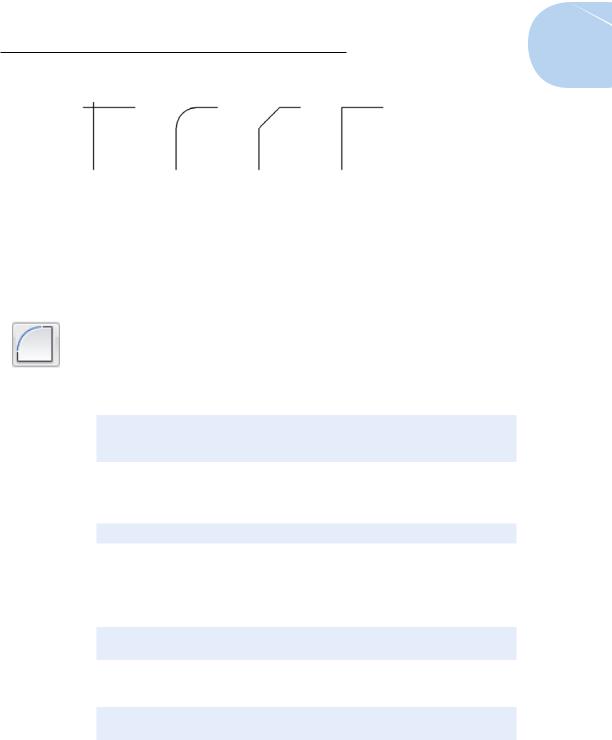
Whereas TRIM, EXTEND, and BREAK alter one object at a time, the FILLET and CHAMFER commands modify a pair of objects. As Figure 11-8 shows, FILLET creates a curved corner between two lines, whereas CHAMFER creates a beveled corner. (In case you wondered, it’s pronounced FILL-et, not fillAY. Saying that you know how to fill-AY may get you a job in a butcher shop, but it will get you strange looks in a design office.)
FILLET and CHAMFER show a preview of the results of the operation as soon as you select the objects to modify. If the fillet radius or the chamfer distances don’t look right in the preview, you can change their values before completing the command.
www.it-ebooks.info
Chapter 11: Edit for Credit 237
Original lines Filleted lines Chamfered lines |
Lines lleted |
|
with zero radius |
Figure 11-8: Cleaning up those corners with FILLET and CHAMFER.
The following steps describe how to use the FILLET command. The CHAMFER command works similarly except that, instead of specifying a fillet radius, you specify either two chamfer distances or a chamfer length and angle.
1.Click the Fillet button on the Home tab’s Modify panel.
FILLET and CHAMFER share a flyout button; if you see a straight-line corner instead of a rounded one, click the flyout arrow to select FILLET.
AutoCAD displays the current fillet settings and prompts you to select the first object for filleting or specify one of three options:
Current settings: Mode = TRIM, Radius = 0.0000
Select first object or [Undo/Polyline/Radius/Trim/ Multiple]:
2. Type R and press Enter to set the fillet radius.
AutoCAD prompts you to specify the fillet radius that it uses for future fillet operations:
Specify fillet radius <0.0000>:
3.Type a fillet radius and press Enter.
The number you type will be the radius of the arc that joins the two lines.
AutoCAD then asks you to select the first object:
Select first object or [Undo/Polyline/Radius/Trim/ Multiple]:
4. Select the first line of the pair that you want to fillet.
AutoCAD prompts you to select the second object for filleting:
Select second object or shift-select to apply corner or [Radius]:
5.Select the second line of the pair that you want to fillet.
AutoCAD fillets the two objects, drawing an arc of the radius that you specified in Step 3.
www.it-ebooks.info