
- •About the Authors
- •Dedication
- •Authors’ Acknowledgments
- •Table of Contents
- •Introduction
- •What’s Not (And What Is) in This Book
- •Mac attack!
- •Who Do We Think You Are?
- •How This Book Is Organized
- •Part I: AutoCAD 101
- •Part II: Let There Be Lines
- •Part III: If Drawings Could Talk
- •Part IV: Advancing with AutoCAD
- •Part V: On a 3D Spree
- •Part VI: The Part of Tens
- •But wait . . . there’s more!
- •Icons Used in This Book
- •A Few Conventions — Just in Case
- •Commanding from the keyboard
- •Tying things up with the Ribbon
- •Where to Go from Here
- •Why AutoCAD?
- •The Importance of Being DWG
- •Seeing the LT
- •Checking System Requirements
- •Suddenly, It’s 2013!
- •AutoCAD Does Windows (And Office)
- •And They’re Off: AutoCAD’s Opening Screens
- •Running with Ribbons
- •Getting with the Program
- •Looking for Mr. Status Bar
- •Let your fingers do the talking: The command window
- •The key(board) to AutoCAD success
- •Keeping tabs on palettes
- •Down the main stretch: The drawing area
- •Fun with F1
- •A Simple Setup
- •Drawing a (Base) Plate
- •Drawing rectangles on the right layers
- •Circling your plate
- •Nuts to you
- •Getting a Closer Look with Zoom and Pan
- •Modifying to Make It Merrier
- •Hip-hip-array!
- •Stretching out
- •Crossing your hatches
- •Following the Plot
- •A Setup Roadmap
- •Choosing your units
- •Weighing up your scales
- •Thinking annotatively
- •Thinking about paper
- •Defending your border
- •A Template for Success
- •Making the Most of Model Space
- •Setting your units
- •Making the drawing area snap-py (and grid-dy)
- •Setting linetype and dimension scales
- •Entering drawing properties
- •Making Templates Your Own
- •Setting Up a Layout in Paper Space
- •Will that be tabs or buttons?
- •View layouts Quick(View)ly
- •Creating a layout
- •Copying and changing layouts
- •Lost in paper space
- •Spaced out
- •A view(port) for drawing in
- •About Paper Space Layouts and Plotting
- •Managing Your Properties
- •Layer one on me!
- •Accumulating properties
- •Creating new layers
- •Manipulating layers
- •Using Named Objects
- •Using AutoCAD DesignCenter
- •Copying layers between drawings
- •Controlling Your Precision
- •Keyboard capers: Coordinate input
- •Understanding AutoCAD’s coordinate systems
- •Grab an object and make it snappy
- •Other Practical Precision Procedures
- •Introducing the AutoCAD Drawing Commands
- •The Straight and Narrow: Lines, Polylines, and Polygons
- •Toeing the line
- •Connecting the lines with polyline
- •Squaring off with rectangles
- •Choosing your sides with polygon
- •(Throwing) Curves
- •Going full circle
- •Arc-y-ology
- •Solar ellipses
- •Splines: The sketchy, sinuous curves
- •Donuts: The circles with a difference
- •Revision clouds on the horizon
- •Scoring Points
- •Commanding and Selecting
- •Command-first editing
- •Selection-first editing
- •Direct object manipulation
- •Choosing an editing style
- •Grab It
- •One-by-one selection
- •Selection boxes left and right
- •Perfecting Selecting
- •AutoCAD Groupies
- •Object Selection: Now You See It . . .
- •Get a Grip
- •About grips
- •A gripping example
- •Move it!
- •Copy, or a kinder, gentler Move
- •A warm-up stretch
- •Your AutoCAD Toolkit
- •The Big Three: Move, Copy, and Stretch
- •Base points and displacements
- •Move
- •Copy
- •Copy between drawings
- •Stretch
- •More Manipulations
- •Mirror
- •Rotate
- •Scale
- •Array
- •Offset
- •Slicing, Dicing, and Splicing
- •Trim and Extend
- •Break
- •Fillet and Chamfer and Blend
- •Join
- •When Editing Goes Bad
- •Zoom and Pan with Glass and Hand
- •The wheel deal
- •Navigating your drawing
- •Controlling your cube
- •Time to zoom
- •A View by Any Other Name . . .
- •Looking Around in Layout Land
- •Degenerating and Regenerating
- •Getting Ready to Write
- •Simply stylish text
- •Taking your text to new heights
- •One line or two?
- •Your text will be justified
- •Using the Same Old Line
- •Turning On Your Annotative Objects
- •Saying More in Multiline Text
- •Making it with Mtext
- •It slices; it dices . . .
- •Doing a number on your Mtext lists
- •Line up in columns — now!
- •Modifying Mtext
- •Gather Round the Tables
- •Tables have style, too
- •Creating and editing tables
- •Take Me to Your Leader
- •Electing a leader
- •Multi options for multileaders
- •How Do You Measure Up?
- •A Field Guide to Dimensions
- •The lazy drafter jumps over to the quick dimension commands
- •Dimension associativity
- •Where, oh where, do my dimensions go?
- •The Latest Styles in Dimensioning
- •Creating and managing dimension styles
- •Let’s get stylish!
- •Adjusting style settings
- •Size Matters
- •Details at other scales
- •Editing Dimensions
- •Editing dimension geometry
- •Editing dimension text
- •Controlling and editing dimension associativity
- •Batten Down the Hatches!
- •Don’t Count Your Hatches. . .
- •Size Matters!
- •We can do this the hard way. . .
- •. . . or we can do this the easy way
- •Annotative versus non-annotative
- •Pushing the Boundary (Of) Hatch
- •Your hatching has no style!
- •Hatch from scratch
- •Editing Hatch Objects
- •You Say Printing, We Say Plotting
- •The Plot Quickens
- •Plotting success in 16 steps
- •Get with the system
- •Configure it out
- •Preview one, two
- •Instead of fit, scale it
- •Plotting the Layout of the Land
- •Plotting Lineweights and Colors
- •Plotting with style
- •Plotting through thick and thin
- •Plotting in color
- •It’s a (Page) Setup!
- •Continuing the Plot Dialog
- •The Plot Sickens
- •Rocking with Blocks
- •Creating Block Definitions
- •Inserting Blocks
- •Attributes: Fill-in-the-Blank Blocks
- •Creating attribute definitions
- •Defining blocks that contain attribute definitions
- •Inserting blocks that contain attribute definitions
- •Edit attribute values
- •Extracting data
- •Exploding Blocks
- •Purging Unused Block Definitions
- •Arraying Associatively
- •Comparing the old and new ARRAY commands
- •Hip, hip, array!
- •Associatively editing
- •Going External
- •Becoming attached to your xrefs
- •Layer-palooza
- •Creating and editing an external reference file
- •Forging an xref path
- •Managing xrefs
- •Blocks, Xrefs, and Drawing Organization
- •Mastering the Raster
- •Attaching a raster image
- •Maintaining your image
- •Theme and Variations: Dynamic Blocks
- •Lights! Parameters!! Actions!!!
- •Manipulating dynamic blocks
- •Maintaining Design Intent
- •Defining terms
- •Forget about drawing with precision!
- •Constrain yourself
- •Understanding Geometric Constraints
- •Applying a little more constraint
- •AutoConstrain yourself!
- •Understanding Dimensional Constraints
- •Practice a little constraint
- •Making your drawing even smarter
- •Using the Parameters Manager
- •Dimensions or constraints — have it both ways!
- •The Internet and AutoCAD: An Overview
- •You send me
- •Send it with eTransmit
- •Rapid eTransmit
- •Bad reception?
- •Help from the Reference Manager
- •Design Web Format — Not Just for the Web
- •All about DWF and DWFx
- •Autodesk Design Review 2013
- •The Drawing Protection Racket
- •Autodesk Weather Forecast: Increasing Cloud
- •Working Solidly in the Cloud
- •Free AutoCAD!
- •Going once, going twice, going 123D
- •Your head planted firmly in the cloud
- •The pros
- •The cons
- •Cloudy with a shower of DWGs
- •AutoCAD 2013 cloud connectivity
- •Tomorrow’s Forecast
- •Understanding 3D Digital Models
- •Tools of the Trade
- •Warp speed ahead
- •Entering the third dimension
- •Untying the Ribbon and opening some palettes
- •Modeling from Above
- •Using 3D coordinate input
- •Using point filters
- •Object snaps and object snap tracking
- •Changing Planes
- •Displaying the UCS icon
- •Adjusting the UCS
- •Navigating the 3D Waters
- •Orbit à go-go
- •Taking a spin around the cube
- •Grabbing the SteeringWheels
- •Visualizing 3D Objects
- •Getting Your 3D Bearings
- •Creating a better 3D template
- •Seeing the world from new viewpoints
- •From Drawing to Modeling in 3D
- •Drawing basic 3D objects
- •Gaining a solid foundation
- •Drawing solid primitives
- •Adding the Third Dimension to 2D Objects
- •Creating 3D objects from 2D drawings
- •Modifying 3D Objects
- •Selecting subobjects
- •Working with gizmos
- •More 3D variants of 2D commands
- •Editing solids
- •Get the 2D Out of Here!
- •A different point of view
- •But wait! There’s more!
- •But wait! There’s less!
- •Do You See What I See?
- •Visualizing the Digital World
- •Adding Lighting
- •Default lighting
- •User-defined lights
- •Sunlight
- •Creating and Applying Materials
- •Defining a Background
- •Rendering a 3D Model
- •Autodesk Feedback Community
- •Autodesk Discussion Groups
- •Autodesk’s Own Bloggers
- •Autodesk University
- •The Autodesk Channel on YouTube
- •The World Wide (CAD) Web
- •Your Local ATC
- •Your Local User Group
- •AUGI
- •Books
- •Price
- •3D Abilities
- •Customization Options
- •Network Licensing
- •Express Tools
- •Parametrics
- •Standards Checking
- •Data Extraction
- •MLINE versus DLINE
- •Profiles
- •Reference Manager
- •And The Good News Is . . .
- •APERTURE
- •DIMASSOC
- •MENUBAR
- •MIRRTEXT
- •OSNAPZ
- •PICKBOX
- •REMEMBERFOLDERS
- •ROLLOVERTIPS
- •TOOLTIPS
- •VISRETAIN
- •And the Bonus Round
- •Index

Chapter 9: Dangerous Curves Ahead 189
Include the revision number. You may need to add a triangle and number, shown in Figure 9-6, to indicate the revision number. A block with an attribute is a good way to handle this requirement: Chapter 17 covers blocks and attributes.
If the revision cloud’s arcs are too small or too large, erase the cloud, restart the REVCLOUD command, and use the command’s Arc Length option to change the minimum and maximum arc lengths. The default minimum and maximum lengths are 0.5 (or 15 in metric drawings). If you make the minimum and maximum lengths equal (which is the default), the lobes will be approximately equal in size. If you make them unequal, there will be more variation in lobe size — you’ll get fluffier clouds. Fortunately, all these options are more than most nonmeteorologists will need.
Scoring Points
We thought about not covering points in this book, but we didn’t want you complaining that AutoCAD 2013 For Dummies is pointless.
The word point describes two different things in AutoCAD:
A location in the drawing that you specify (by typing coordinates or clicking with the mouse)
An object that you draw with the POINT command
Throughout this chapter and most of the book, we tell you to specify points — that’s the location meaning. This section tells you how to draw point objects.
A point object in AutoCAD can serve two purposes:
Points often identify specific locations in your drawing to other people who look at the drawing. A point can be something that displays on the screen, either as a tiny dot or as another symbol, such as a cross with a circle around it.
You can use points as precise object snap locations. Think of them as construction points. For example, when you’re laying out a new building, you might draw point objects at some of the engineering survey points and then snap to those points as you sketch the building’s shape with the PLINE command. You use the Node Object Snap mode to snap to AutoCAD point objects.
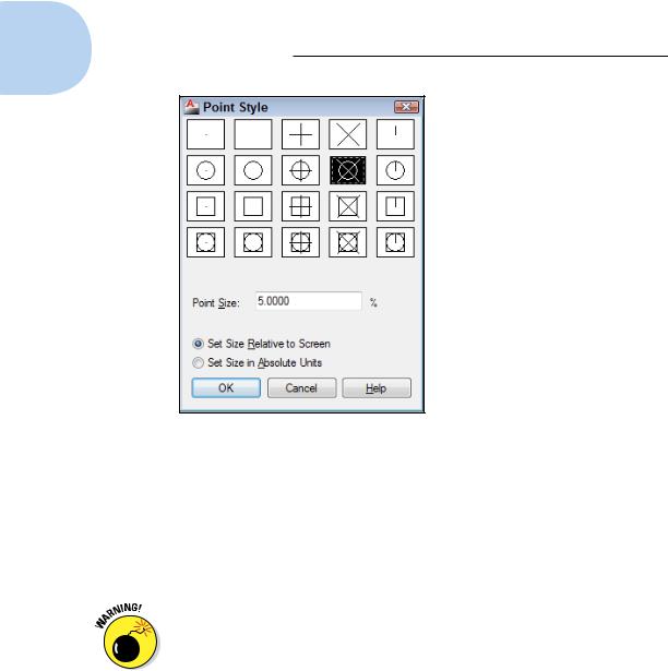
What makes AutoCAD point objects complicated is their almost limitless range of display options, provided to accommodate the two different kinds of purposes just described (and possibly some others that we haven’t figured out yet). You use the Point Style dialog box, shown in Figure 9-7, to specify how points should look in the current drawing.
www.it-ebooks.info

190 Part II: Let There Be Lines
Figure 9-7: The Point Style dialog box controls the way point objects appear onscreen.
The Point Style dialog box can be found on the Home tab’s Utilities panel slideout, or by typing its command name — which happens to be about the least intuitive command name in all of AutoCAD: DDPTYPE (pronounced dee dee pee type). The top portion of the dialog box shows the available point display styles. Most of the choices do pretty much the same thing. Just click one of the squares that says, “Hey, that’s a good point!” to you.
The first choice, a single-pixel dot, is hard to see on the screen, and the second choice, invisible (a stealth point?), is impossible to see. Avoid these choices if you want your point objects to show up on the screen and on plots. The single-pixel dot, which is the default display style, works well if you use point objects as object snap locations and don’t want obtrusive points on your plots.
The remaining settings in the Point Style dialog box control the size at which points appear on the screen at different zoom magnifications. The default settings often work fine, but if you’re not satisfied with them, click the Help button in the dialog box to find out how to change them.
www.it-ebooks.info

Chapter 9: Dangerous Curves Ahead 191
After you specify the point style, placing points onscreen is easy. The following example shows you how; just type POINT and press Enter.
Command: POINT
Current point modes: PDMODE=0 PDSIZE=0.0000
Specify a point: pick or type the coordinates of a location in the drawing
The PDMODE and PDSIZE items listed in the command window are system variables that correspond to the point display mode and display size options in the Point Style dialog box. If you want to know exactly how the system variables correspond to the dialog box choices, you have all the makings of a successful CAD nerd. Click the Help button in the Point Style dialog box to find out more (about the system variables — not about yourself).
www.it-ebooks.info

192 Part II: Let There Be Lines
www.it-ebooks.info