

- •Analysis and Application of Analog Electronic Circuits to Biomedical Instrumentation
- •Dedication
- •Preface
- •Reader Background
- •Rationale
- •Description of the Chapters
- •Features
- •The Author
- •Table of Contents
- •1.1 Introduction
- •1.2 Sources of Endogenous Bioelectric Signals
- •1.3 Nerve Action Potentials
- •1.4 Muscle Action Potentials
- •1.4.1 Introduction
- •1.4.2 The Origin of EMGs
- •1.5 The Electrocardiogram
- •1.5.1 Introduction
- •1.6 Other Biopotentials
- •1.6.1 Introduction
- •1.6.2 EEGs
- •1.6.3 Other Body Surface Potentials
- •1.7 Discussion
- •1.8 Electrical Properties of Bioelectrodes
- •1.9 Exogenous Bioelectric Signals
- •1.10 Chapter Summary
- •2.1 Introduction
- •2.2.1 Introduction
- •2.2.4 Schottky Diodes
- •2.3.1 Introduction
- •2.4.1 Introduction
- •2.5.1 Introduction
- •2.5.5 Broadbanding Strategies
- •2.6 Photons, Photodiodes, Photoconductors, LEDs, and Laser Diodes
- •2.6.1 Introduction
- •2.6.2 PIN Photodiodes
- •2.6.3 Avalanche Photodiodes
- •2.6.4 Signal Conditioning Circuits for Photodiodes
- •2.6.5 Photoconductors
- •2.6.6 LEDs
- •2.6.7 Laser Diodes
- •2.7 Chapter Summary
- •Home Problems
- •3.1 Introduction
- •3.2 DA Circuit Architecture
- •3.4 CM and DM Gain of Simple DA Stages at High Frequencies
- •3.4.1 Introduction
- •3.5 Input Resistance of Simple Transistor DAs
- •3.7 How Op Amps Can Be Used To Make DAs for Medical Applications
- •3.7.1 Introduction
- •3.8 Chapter Summary
- •Home Problems
- •4.1 Introduction
- •4.3 Some Effects of Negative Voltage Feedback
- •4.3.1 Reduction of Output Resistance
- •4.3.2 Reduction of Total Harmonic Distortion
- •4.3.4 Decrease in Gain Sensitivity
- •4.4 Effects of Negative Current Feedback
- •4.5 Positive Voltage Feedback
- •4.5.1 Introduction
- •4.6 Chapter Summary
- •Home Problems
- •5.1 Introduction
- •5.2.1 Introduction
- •5.2.2 Bode Plots
- •5.5.1 Introduction
- •5.5.3 The Wien Bridge Oscillator
- •5.6 Chapter Summary
- •Home Problems
- •6.1 Ideal Op Amps
- •6.1.1 Introduction
- •6.1.2 Properties of Ideal OP Amps
- •6.1.3 Some Examples of OP Amp Circuits Analyzed Using IOAs
- •6.2 Practical Op Amps
- •6.2.1 Introduction
- •6.2.2 Functional Categories of Real Op Amps
- •6.3.1 The GBWP of an Inverting Summer
- •6.4.3 Limitations of CFOAs
- •6.5 Voltage Comparators
- •6.5.1 Introduction
- •6.5.2. Applications of Voltage Comparators
- •6.5.3 Discussion
- •6.6 Some Applications of Op Amps in Biomedicine
- •6.6.1 Introduction
- •6.6.2 Analog Integrators and Differentiators
- •6.7 Chapter Summary
- •Home Problems
- •7.1 Introduction
- •7.2 Types of Analog Active Filters
- •7.2.1 Introduction
- •7.2.3 Biquad Active Filters
- •7.2.4 Generalized Impedance Converter AFs
- •7.3 Electronically Tunable AFs
- •7.3.1 Introduction
- •7.3.3 Use of Digitally Controlled Potentiometers To Tune a Sallen and Key LPF
- •7.5 Chapter Summary
- •7.5.1 Active Filters
- •7.5.2 Choice of AF Components
- •Home Problems
- •8.1 Introduction
- •8.2 Instrumentation Amps
- •8.3 Medical Isolation Amps
- •8.3.1 Introduction
- •8.3.3 A Prototype Magnetic IsoA
- •8.4.1 Introduction
- •8.6 Chapter Summary
- •9.1 Introduction
- •9.2 Descriptors of Random Noise in Biomedical Measurement Systems
- •9.2.1 Introduction
- •9.2.2 The Probability Density Function
- •9.2.3 The Power Density Spectrum
- •9.2.4 Sources of Random Noise in Signal Conditioning Systems
- •9.2.4.1 Noise from Resistors
- •9.2.4.3 Noise in JFETs
- •9.2.4.4 Noise in BJTs
- •9.3 Propagation of Noise through LTI Filters
- •9.4.2 Spot Noise Factor and Figure
- •9.5.1 Introduction
- •9.6.1 Introduction
- •9.7 Effect of Feedback on Noise
- •9.7.1 Introduction
- •9.8.1 Introduction
- •9.8.2 Calculation of the Minimum Resolvable AC Input Voltage to a Noisy Op Amp
- •9.8.5.1 Introduction
- •9.8.5.2 Bridge Sensitivity Calculations
- •9.8.7.1 Introduction
- •9.8.7.2 Analysis of SNR Improvement by Averaging
- •9.8.7.3 Discussion
- •9.10.1 Introduction
- •9.11 Chapter Summary
- •Home Problems
- •10.1 Introduction
- •10.2 Aliasing and the Sampling Theorem
- •10.2.1 Introduction
- •10.2.2 The Sampling Theorem
- •10.3 Digital-to-Analog Converters (DACs)
- •10.3.1 Introduction
- •10.3.2 DAC Designs
- •10.3.3 Static and Dynamic Characteristics of DACs
- •10.4 Hold Circuits
- •10.5 Analog-to-Digital Converters (ADCs)
- •10.5.1 Introduction
- •10.5.2 The Tracking (Servo) ADC
- •10.5.3 The Successive Approximation ADC
- •10.5.4 Integrating Converters
- •10.5.5 Flash Converters
- •10.6 Quantization Noise
- •10.7 Chapter Summary
- •Home Problems
- •11.1 Introduction
- •11.2 Modulation of a Sinusoidal Carrier Viewed in the Frequency Domain
- •11.3 Implementation of AM
- •11.3.1 Introduction
- •11.3.2 Some Amplitude Modulation Circuits
- •11.4 Generation of Phase and Frequency Modulation
- •11.4.1 Introduction
- •11.4.3 Integral Pulse Frequency Modulation as a Means of Frequency Modulation
- •11.5 Demodulation of Modulated Sinusoidal Carriers
- •11.5.1 Introduction
- •11.5.2 Detection of AM
- •11.5.3 Detection of FM Signals
- •11.5.4 Demodulation of DSBSCM Signals
- •11.6 Modulation and Demodulation of Digital Carriers
- •11.6.1 Introduction
- •11.6.2 Delta Modulation
- •11.7 Chapter Summary
- •Home Problems
- •12.1 Introduction
- •12.2.1 Introduction
- •12.2.2 The Analog Multiplier/LPF PSR
- •12.2.3 The Switched Op Amp PSR
- •12.2.4 The Chopper PSR
- •12.2.5 The Balanced Diode Bridge PSR
- •12.3 Phase Detectors
- •12.3.1 Introduction
- •12.3.2 The Analog Multiplier Phase Detector
- •12.3.3 Digital Phase Detectors
- •12.4 Voltage and Current-Controlled Oscillators
- •12.4.1 Introduction
- •12.4.2 An Analog VCO
- •12.4.3 Switched Integrating Capacitor VCOs
- •12.4.6 Summary
- •12.5 Phase-Locked Loops
- •12.5.1 Introduction
- •12.5.2 PLL Components
- •12.5.3 PLL Applications in Biomedicine
- •12.5.4 Discussion
- •12.6 True RMS Converters
- •12.6.1 Introduction
- •12.6.2 True RMS Circuits
- •12.7 IC Thermometers
- •12.7.1 Introduction
- •12.7.2 IC Temperature Transducers
- •12.8 Instrumentation Systems
- •12.8.1 Introduction
- •12.8.5 Respiratory Acoustic Impedance Measurement System
- •12.9 Chapter Summary
- •References
472 |
Analysis and Application of Analog Electronic Circuits |
|||||
|
|
|
|
B |
ir− |
|
|
|
|
|
|
|
|
|
|
b |
|
|
a |
|
ym(t) |
im− |
|
C |
A |
|
vr(t) |
|
ir− |
|
+ |
|
imd |
|
|
c |
vd |
vd |
d |
|
|
|
|
|
+ |
|
||
|
|
|
|
im− |
|
|
Signal |
|
|
|
ir− |
|
Reference |
|
|
|
D |
imc |
||
transformer |
im− |
|
|
transformer |
||
|
|
|
|
|||
|
|
|
|
ir− |
|
+ |
|
|
|
|
|
|
|
|
|
|
|
|
R |
vz(t) |
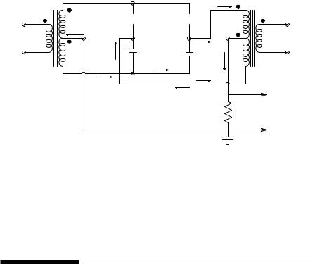
FIGURE 12.4
The diode bridge PSR when diodes c and d are conducting, and a and b are blocking current flow.
carrier frequency of the BDBPSR is determined by the types of diodes used. Schottky diodes switch extremely fast because they are majority carrier devices and there is no minority carrier storage at the junction; they will give satisfactory results in the hundreds of megahertz (Yang, 1988).
12.3 Phase Detectors
12.3.1Introduction
A phase detector (PD) operates on two periodic signals of the same frequency and returns a dc signal voltage proportional to the phase difference between the two signals. PDs have several important applications. They are used in lock-in amplifiers to ensure the reference signal retains the correct phase relation with the input carrier for optimum demodulation (McDonald and Northrop, 1993). They are also used as an essential component in all phaselock loops, which have many applications. Sections 12.4.5 and 12.8.3 will show that a PD is necessary in a phase-locked laser radar (LAVERA) system. PDs are also used in the impedance and autobalancing bridges used to measure body impedance or admittance. PDs can be subdivided into analog and digital designs.
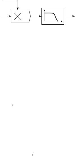
12.3.2The Analog Multiplier Phase Detector
The simplest analog phase detector (PD) is the analog multiplier followed by a low-pass filter, as shown in Figure 12.5. The input sinusoid with the phase to be measured is
© 2004 by CRC Press LLC
Examples of Special Analog Circuits and Systems |
473 |
Vs sin(ωc t + θ)
|
|
|
LPF |
|
|
|
___ |
|
z(t) |
1 |
z(t) |
Vr cos(ωc t) |
|
|
|
|
|
f |
|
|
|
|
|
AM |
|
0 |
|
|
|
|
FIGURE 12.5
Block diagram of an analog multiplier phase detector.
vs(t) = Vs sin(ωc t + θ) |
(12.8) |
The reference sinusoid is the quadrature signal,
vr(t) = Vr cos(ωc t + φ) |
(12.9) |
and the output of the analog multiplier is:
z(t) = vr (t)vs (t) 10 |
(12.10) |
By trigonometric identity:
z(t) = |
( r s |
){ |
( |
c |
t + θ + φ |
) |
} |
(12.11) |
V V 20 |
sin |
2ω |
|
+ sin(θ − φ) |
||||
The LPF attenuates the 2ωc frequency term; its output simply estimates
the average: |
|
||||
|
|
|
= (VrVs 20)sin(θ − φ) |
|
|
|
z(t) |
(12.12) |
|||
Thus, for θe < 15∞, |
|
||||
|
|
|
(VrVs 20)(θc ) |
|
|
|
|
z(t) |
(12.13) |
||
where θe ∫ (θ − φ) is in radians.
A systems approximation for the analog multiplier PD is shown in Figure 12.6. Note that for small phase error, the PD is linear, but exhibits periodic nonlinear behavior. Because the two coherent signals must be 90∞ out of phase for the AM PD to work, it is called a quadrature PD.
As in the case of the switched op amp PSR, it is possible to have a switched op amp or transistor PD in which the input analog signal, vs(t), given by Equation 12.8 is effectively multiplied by a ±1 reference quadrature square wave given by sgn{Vr cos(ωc t)}. To demonstrate that the switched PD gives the same result as the analog multiplier PD, recall that a unity square wave
© 2004 by CRC Press LLC

474 |
Analysis and Application of Analog Electronic Circuits |
z(t)
vs(t) = Vs sin(ωct + θ) 
vr(t) = Vr cos(ωct + φ) |
|
|
|
A |
|
|
|
|
|
||
|
|
|
|
|
|
|
|
|
θe |
KpVsVr |
z |
θ |
|
|
sin θe |
|
|
|
|
|
|
||
|
|
− |
20 |
|
|
|
|
|
|
||
|
|
φ |
B |
|
|
|
|
|
|
|
|
|
|
|
θe |
KpVsVr |
z |
θ |
|
|
|
|
|
|
|
|
|
||
|
|
− |
20 |
|
|
|
|
|
|
||
|
|
φ |
C |
|
|
FIGURE 12.6
(A) Analog multiplier quadrature phase detector without LPF. (B) Sin(θ − φ) approximation to analog multiplier quadrature phase detector. (C) When Ωθ−φΩ < 15∞, then z (θ − φ).
can be expressed by its Fourier series. The Fourier series for a periodic time function, f(t), can be written as the infinite harmonic sum (Northrop, 2003):
•
f(t) = a0 + an cos(nωot)+ bn sin(nωot)
n=1
where the fundamental (or carrier) frequency is defined as:
ωo ∫ 2π/T r/s
a0 = the average value of f(t)
(12.14)
(12.15A)
(12.15B)
T = period of f(t) |
(12.15C) |
||
The coefficients of the Fourier series are given by: |
|
||
|
|
T 2 |
|
an ∫ |
2 |
f(t)cos(nωot)dt |
(12.16) |
T |
|||
|
|
−T 2 |
|
© 2004 by CRC Press LLC

Examples of Special Analog Circuits and Systems |
475 |
||
|
|
T 2 |
|
bn ∫ |
2 |
f(t)sin(nωot)dt |
(12.17) |
T |
|||
|
|
−T 2 |
|
To show that the product, z(t) = Vs sin(ωo t + θe) sgn{Vr cos(ωo t)}, when averaged, gives phase detection, use the fundamental frequency (n = 1) term in the F-series for the cosine square wave, sgn{Vr cos(ωo t)}. The higher-order harmonics in the F-series lead to output frequencies that are multiples of ωo and therefore filtered out. Note also for sgn{Vr cos(ωot)} that a0 = 0 and bn = 0 because f(t) is an even function. Thus, f(t) is approximated by:
f1(t) (4 π)cos(ωot) |
(12.18) |
Thus,
z(t) = (4Vs  π)sin(ωot + θe )cos(ωot) = (2Vs
  π)[sin(2ωot + θe )+ sin(θe )] (12.19)
After low-pass filtering, the desired output is:
|
= (2Vs π)sin(θe ) (2Vs π)(θe ), (θe ) in radians. |
|
z(t) |
(12.20) |
The latter term in Equation 12.20 is valid for the phase difference between input and output waves, θe < 15∞. Note that this PD has the same sin(θ) nonlinearity as the pure analog multiplier PD. This type of phase detector is used in many IC phase-lock loop designs.
12.3.3Digital Phase Detectors
Analog phase detectors based on ideal multiplication require a quadrature reference signal and a low-pass filter, and produce a nonlinear output given by sin(θe). Digital phase detectors, on the other hand, accept two logic signal inputs and generally give a low-pass filtered output that is linear over some range of θe but periodic in θe.
The first digital phase detector to be examined is the exclusive NOR PD, illustrated with waveforms in Figure 12.7. This PD accepts two TTL square waves with 50% duty cycles, which have the same frequency but differ in phase by an amount, θe. The op amp has two functions: (1) it subtracts approximately 1.7 V from the Q waveform, so when Q has a 50% duty cycle, the average output, Vz(t) = 0; (2) it low-pass filters the offset Q signal and outputs its average value. Note that Vz(t) = 0 when θe = ±kπ/2, k odd. Like the analog multiplier PD, the ENOR PD is also a quadrature PD. Note that the average output is linear with θe over a range of 0 to π radians, but is also periodic in θe with period 2π. The frequency of the Q output is 2/T pps.
© 2004 by CRC Press LLC
476 |
Analysis and Application of Analog Electronic Circuits |
P
3.4 V
S
Q
P |
Q |
|
P |
|
|
3.4 V |
|
|
|
|
|
S |
|
|
|
|
C |
|
S |
|
|
|
|
R |
|
|
|
R |
|
R |
__ Q |
|
|
|
|
|
|
|
Vz |
− 1.7 V |
|
|
|
P
3.4 V
S
Q
__ |
|
|
|
|
|
Vz |
|
|
|
|
|
1.7 V |
|
|
|
|
|
π/2 |
π |
3π/2 |
2π |
3π |
θe |
−π/2 |
|
||||
|
|
|
|
|
|
−1.7 V |
|
|
|
|
|
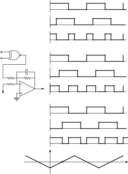
FIGURE 12.7
An exclusive NOR digital phase detector and examples of its waveforms. The bottom graph shows a plot of the (offset) average output voltage of this PD vs. the phase difference between TTL inputs P and S. Note the zeros are at odd integer multiples of (π/2).
Another linear digital PD can be realized with a simple RS flip-flop (RSFF), as shown in Figure 12.8. Note that the RSFF PD uses the same DC offset and LPF op amp circuit as the ENOR PD. Inputs to the RSFF PD are required to be narrow complementary pulses, such as those that can be generated by the rising edges of the two TTL square waves triggering one-shot multivibrators’
© 2004 by CRC Press LLC
Examples of Special Analog Circuits and Systems |
477 |
P
3.4 V
S
P |
__ |
__ |
|
Q |
|||
|
Q |
||
|
|
Q
P
3.4 V
S
|
C |
|
S |
|
|
|
|
R |
|
|
|
R |
R |
__ |
__ |
|
|
Q |
|
|
|
Vz |
|
|
|
|
|
− 1.7 V |
|
|
|
|
|
|
P |
|
|
|
3.4 V |
|
|
|
S |
|
|
|
__ |
2π |
4π |
6π |
θe
2π |
4π |
6π |
θe = π |
3π |
|
2π |
4π |
6π |
θe
Q
__
 Vz
Vz
|
1.7 V |
|
|
|
|
|
−π |
π |
2π |
3π |
4π |
5π |
θe |
|
||||||
|
−1.7 V |
|
|
|
|
|
FIGURE 12.8
The RS flip-flop PD and its waveforms. The bottom graph shows a plot of the (offset) average output voltage of this PD vs. the phase difference between TTL inputs P and S. Note the significant zeros are at odd integer multiples of π.
(one-shots) complementary outputs. Note that the Vz(t)vs θe characteristic is also periodic with period 2π, but the linear range extends the full 0 ≤ θe ≤ 2π range. This PD’s characteristic has no negative slope portion. The Vz (θe) curve has its zero at θe = π, so it is not a quadrature system. The reference square wave needs only logical inversion before triggering the one-shot.
© 2004 by CRC Press LLC
478 |
Analysis and Application of Analog Electronic Circuits |
R U
RSFF
RSFF
V D
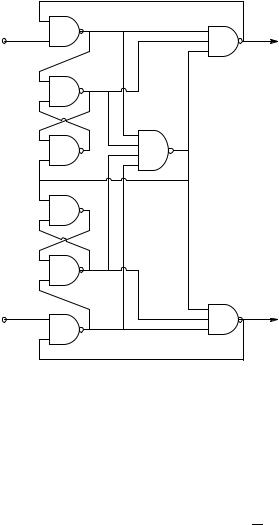
FIGURE 12.9
A combinational/sequential logic PD based on the Motorola MC4044 digital PD IC.
More complex linear digital phase detectors have been devised. One venerable design based on the Motorola MC4044 IC is shown in Figure 12.9. This PD’s architecture is made up from various NAND gates. Note the two RS flip-flops in the center of the left-hand column. Figure 12.10 illustrates the input and output waveforms at nodes R, V, U, and D, respectively. The digital waveforms for V lagging R (top set) and for V leading R (middle set) are shown. Subtracting U from D by a simple op amp DA and low-pass filtering the difference to recover the average output, Vz , yields a linear output voltage, vs θe, over a full ±2π interval, as shown in Figure 12.11.
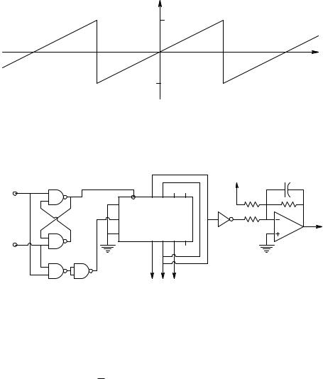
Another logic chip-based digital PD is shown in Figure 12.12. This circuit uses a 7495 (or Fairchild 9300) four-bit, bidirectional shift register (Northrop, 1990). As a PD in a PLL, it can detect lock (ωp = ωr) by Q0 = LO, Q2 = HI, and Q1 has the TTL phase signal similar to the RSFF output. If ωp > ωr, then Q0 = LO, Q1 = LO, and Q2 has a duty cycle proportional to (ωp − ωr). If ωp < ωr, then Q1 = HI, Q2 = HI, and Q0 has a duty cycle proportional to (ωr − ωp). Note that this phase-frequency detector’s phase difference output on Q1 is not periodic in θe, like other digital PDs; it saturates LO for ωp > ωr and saturates HI when ωp < ωr. Q1 has a 50% duty cycle when ωp = ωr radians, giving Vz (θe) = 0. Note that the P and R inputs must be narrow complementary pulses derived from the`Q outputs of one-shots.
© 2004 by CRC Press LLC

Examples of Special Analog Circuits and Systems |
479 |
R
V θe
U
D
R
 θe
θe
V
U
D
|
|
R2 |
C |
|
|
|
|
|
|
U |
R1 |
|
|
|
|
R1 |
R3 |
__ |
|
|
|
|||
D |
R1 |
Vz(t) |
|
Vz |
|
|
|
||
|
|
|
|
DA |
LPF |
|
|
R2 |
|
FIGURE 12.10
Top: example of the 4044 PD’s waveforms for V lagging R. Middle: example of the 4044 PD’s waveforms for V leading R. Bottom: op amp DA and low-pass filter used to condition the 4044 PD’s outputs, U and D.
Because of their linearity, digital PhDs are useful in instrumentation schemes in which phase must be measured. Note that it is possible to run two noise-free sinusoidal signals through comparators with hysteresis to generate two digital signals that can be measured with a simple digital PD.
A microcomputer-based, frequency-independent digital phase meter with one-millidegree resolution was designed and tested by Du (1993) in the
© 2004 by CRC Press LLC
480 |
Analysis and Application of Analog Electronic Circuits |
|
|
__ |
|
|
|
|
|
Vz |
|
|
|
|
|
Vzmax |
|
|
|
−4π |
−2π |
π |
2π |
4π |
θe |
|
|
−Vzmax |
|
|
|
FIGURE 12.11
Average output voltage vs. input phase difference for the 4044 PD with the op amp signal conditioner. Note each linear segment spans a full ±2 π radians, and has zero output for zero phase difference between R and V.
Q |
|
|
|
−1.7V |
C |
|
|
|
|
|
|
||
R |
|
|
|
R |
|
|
|
P0 |
P1 |
P2 |
|
|
|
J PE |
P3 |
|
|
|||
|
|
|
|
|
|
|
|
|
|
|
R |
R |
__ |
CLK |
F9300 |
|
|
|
Vz |
|
K |
Q0 |
Q1 |
Q2 |
Q3 |
|
|
|
|
|
||||
P
FIGURE 12.12
A shift register-based digital phase-frequency detector.
author’s laboratory. The reference digital input channel was also the input to a Signetics NE564 phase-lock loop that used a divide-by 360,000 counter between its VCO and its phase detector. Thus, the VCO TTL output was phase locked to the input R signal and its output frequency was 360,000 times the input frequency, fo.
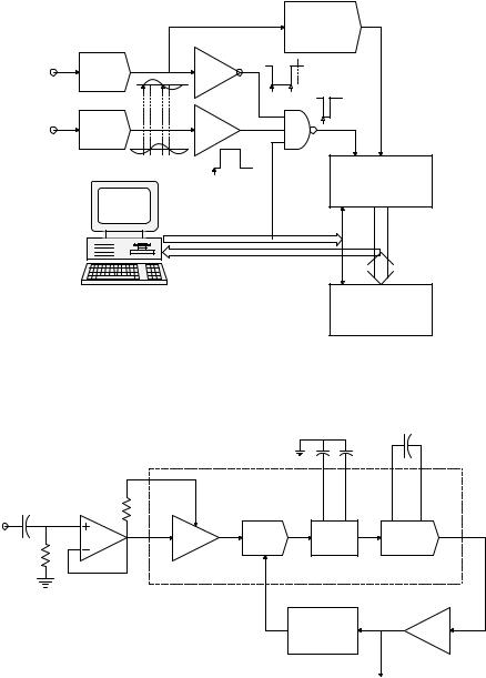
The high level of the QR comparator output is NANDed with the QS output of the signal comparator. Any phase shift between VR and VS produces a narrow complementary gating pulse at the output of the NAND gate that allows the PLL output at 360,000 fo to be counted. The count occurs once per cycle for a preset number of cycles. The total count is stored in the shift registers (74F299) and then downloaded into the PC for averaging. Each count is the phase lag between VR and VS in millidegrees and is independent of the frequency of the inputs.
Du’s phase meter worked with input frequencies, fo, of up to 100 Hz and gave a numerical output of θe and its statistics. Figure 12.13 and Figure 12.14 illustrate the architecture of the millidegree phase meter and the PLL used
© 2004 by CRC Press LLC
Examples of Special Analog Circuits and Systems |
481 |
__
Signal QR VR condit.
VS |
Signal |
|
|
condit. |
QS |
||
|
en
PLL
360 000 fo
__
|
CEP CP |
|
Counters |
|
__ |
|
MR |
Control output |
24 bit |
Phase data |
16 bit |
__
MR
Shift registers
FIGURE 12.13
Architecture of the millidegree phase detector devised by Du (1993). The system is based on a phase-lock loop with a clock that runs 360,000 times faster than the input frequency.
Co = 18 pF
150 pF 150 pF
VR |
|
Loop |
|
|
TL072 |
PD |
VCO |
||
filter |
||||
|
|
|
||
Limiter |
fo |
NE564 |
PLL |
|
|
|
|||
|
|
360 000 |
Buffer |
|
|
|
freq. divider |
||
|
|
|
360 000 fo
FIGURE 12.14
Detailed block diagram of Du’s PLL.
as a ∞360,000 frequency multiplier. Du’s system was used in dielectric materials measurements where it was desired to measure minute phase shifts caused by dielectric losses at power line frequencies.
© 2004 by CRC Press LLC