

- •Analysis and Application of Analog Electronic Circuits to Biomedical Instrumentation
- •Dedication
- •Preface
- •Reader Background
- •Rationale
- •Description of the Chapters
- •Features
- •The Author
- •Table of Contents
- •1.1 Introduction
- •1.2 Sources of Endogenous Bioelectric Signals
- •1.3 Nerve Action Potentials
- •1.4 Muscle Action Potentials
- •1.4.1 Introduction
- •1.4.2 The Origin of EMGs
- •1.5 The Electrocardiogram
- •1.5.1 Introduction
- •1.6 Other Biopotentials
- •1.6.1 Introduction
- •1.6.2 EEGs
- •1.6.3 Other Body Surface Potentials
- •1.7 Discussion
- •1.8 Electrical Properties of Bioelectrodes
- •1.9 Exogenous Bioelectric Signals
- •1.10 Chapter Summary
- •2.1 Introduction
- •2.2.1 Introduction
- •2.2.4 Schottky Diodes
- •2.3.1 Introduction
- •2.4.1 Introduction
- •2.5.1 Introduction
- •2.5.5 Broadbanding Strategies
- •2.6 Photons, Photodiodes, Photoconductors, LEDs, and Laser Diodes
- •2.6.1 Introduction
- •2.6.2 PIN Photodiodes
- •2.6.3 Avalanche Photodiodes
- •2.6.4 Signal Conditioning Circuits for Photodiodes
- •2.6.5 Photoconductors
- •2.6.6 LEDs
- •2.6.7 Laser Diodes
- •2.7 Chapter Summary
- •Home Problems
- •3.1 Introduction
- •3.2 DA Circuit Architecture
- •3.4 CM and DM Gain of Simple DA Stages at High Frequencies
- •3.4.1 Introduction
- •3.5 Input Resistance of Simple Transistor DAs
- •3.7 How Op Amps Can Be Used To Make DAs for Medical Applications
- •3.7.1 Introduction
- •3.8 Chapter Summary
- •Home Problems
- •4.1 Introduction
- •4.3 Some Effects of Negative Voltage Feedback
- •4.3.1 Reduction of Output Resistance
- •4.3.2 Reduction of Total Harmonic Distortion
- •4.3.4 Decrease in Gain Sensitivity
- •4.4 Effects of Negative Current Feedback
- •4.5 Positive Voltage Feedback
- •4.5.1 Introduction
- •4.6 Chapter Summary
- •Home Problems
- •5.1 Introduction
- •5.2.1 Introduction
- •5.2.2 Bode Plots
- •5.5.1 Introduction
- •5.5.3 The Wien Bridge Oscillator
- •5.6 Chapter Summary
- •Home Problems
- •6.1 Ideal Op Amps
- •6.1.1 Introduction
- •6.1.2 Properties of Ideal OP Amps
- •6.1.3 Some Examples of OP Amp Circuits Analyzed Using IOAs
- •6.2 Practical Op Amps
- •6.2.1 Introduction
- •6.2.2 Functional Categories of Real Op Amps
- •6.3.1 The GBWP of an Inverting Summer
- •6.4.3 Limitations of CFOAs
- •6.5 Voltage Comparators
- •6.5.1 Introduction
- •6.5.2. Applications of Voltage Comparators
- •6.5.3 Discussion
- •6.6 Some Applications of Op Amps in Biomedicine
- •6.6.1 Introduction
- •6.6.2 Analog Integrators and Differentiators
- •6.7 Chapter Summary
- •Home Problems
- •7.1 Introduction
- •7.2 Types of Analog Active Filters
- •7.2.1 Introduction
- •7.2.3 Biquad Active Filters
- •7.2.4 Generalized Impedance Converter AFs
- •7.3 Electronically Tunable AFs
- •7.3.1 Introduction
- •7.3.3 Use of Digitally Controlled Potentiometers To Tune a Sallen and Key LPF
- •7.5 Chapter Summary
- •7.5.1 Active Filters
- •7.5.2 Choice of AF Components
- •Home Problems
- •8.1 Introduction
- •8.2 Instrumentation Amps
- •8.3 Medical Isolation Amps
- •8.3.1 Introduction
- •8.3.3 A Prototype Magnetic IsoA
- •8.4.1 Introduction
- •8.6 Chapter Summary
- •9.1 Introduction
- •9.2 Descriptors of Random Noise in Biomedical Measurement Systems
- •9.2.1 Introduction
- •9.2.2 The Probability Density Function
- •9.2.3 The Power Density Spectrum
- •9.2.4 Sources of Random Noise in Signal Conditioning Systems
- •9.2.4.1 Noise from Resistors
- •9.2.4.3 Noise in JFETs
- •9.2.4.4 Noise in BJTs
- •9.3 Propagation of Noise through LTI Filters
- •9.4.2 Spot Noise Factor and Figure
- •9.5.1 Introduction
- •9.6.1 Introduction
- •9.7 Effect of Feedback on Noise
- •9.7.1 Introduction
- •9.8.1 Introduction
- •9.8.2 Calculation of the Minimum Resolvable AC Input Voltage to a Noisy Op Amp
- •9.8.5.1 Introduction
- •9.8.5.2 Bridge Sensitivity Calculations
- •9.8.7.1 Introduction
- •9.8.7.2 Analysis of SNR Improvement by Averaging
- •9.8.7.3 Discussion
- •9.10.1 Introduction
- •9.11 Chapter Summary
- •Home Problems
- •10.1 Introduction
- •10.2 Aliasing and the Sampling Theorem
- •10.2.1 Introduction
- •10.2.2 The Sampling Theorem
- •10.3 Digital-to-Analog Converters (DACs)
- •10.3.1 Introduction
- •10.3.2 DAC Designs
- •10.3.3 Static and Dynamic Characteristics of DACs
- •10.4 Hold Circuits
- •10.5 Analog-to-Digital Converters (ADCs)
- •10.5.1 Introduction
- •10.5.2 The Tracking (Servo) ADC
- •10.5.3 The Successive Approximation ADC
- •10.5.4 Integrating Converters
- •10.5.5 Flash Converters
- •10.6 Quantization Noise
- •10.7 Chapter Summary
- •Home Problems
- •11.1 Introduction
- •11.2 Modulation of a Sinusoidal Carrier Viewed in the Frequency Domain
- •11.3 Implementation of AM
- •11.3.1 Introduction
- •11.3.2 Some Amplitude Modulation Circuits
- •11.4 Generation of Phase and Frequency Modulation
- •11.4.1 Introduction
- •11.4.3 Integral Pulse Frequency Modulation as a Means of Frequency Modulation
- •11.5 Demodulation of Modulated Sinusoidal Carriers
- •11.5.1 Introduction
- •11.5.2 Detection of AM
- •11.5.3 Detection of FM Signals
- •11.5.4 Demodulation of DSBSCM Signals
- •11.6 Modulation and Demodulation of Digital Carriers
- •11.6.1 Introduction
- •11.6.2 Delta Modulation
- •11.7 Chapter Summary
- •Home Problems
- •12.1 Introduction
- •12.2.1 Introduction
- •12.2.2 The Analog Multiplier/LPF PSR
- •12.2.3 The Switched Op Amp PSR
- •12.2.4 The Chopper PSR
- •12.2.5 The Balanced Diode Bridge PSR
- •12.3 Phase Detectors
- •12.3.1 Introduction
- •12.3.2 The Analog Multiplier Phase Detector
- •12.3.3 Digital Phase Detectors
- •12.4 Voltage and Current-Controlled Oscillators
- •12.4.1 Introduction
- •12.4.2 An Analog VCO
- •12.4.3 Switched Integrating Capacitor VCOs
- •12.4.6 Summary
- •12.5 Phase-Locked Loops
- •12.5.1 Introduction
- •12.5.2 PLL Components
- •12.5.3 PLL Applications in Biomedicine
- •12.5.4 Discussion
- •12.6 True RMS Converters
- •12.6.1 Introduction
- •12.6.2 True RMS Circuits
- •12.7 IC Thermometers
- •12.7.1 Introduction
- •12.7.2 IC Temperature Transducers
- •12.8 Instrumentation Systems
- •12.8.1 Introduction
- •12.8.5 Respiratory Acoustic Impedance Measurement System
- •12.9 Chapter Summary
- •References

10
Digital Interfaces
10.1 Introduction
Digital interfaces enable us to convert analog signals to a digital format that can be an input to a computer or a digital data storage system and, conversely, take digital data from a computer and convert it to an analog signal (voltage, current, light intensity, etc.). An analog-to-digital converter (ADC) performs the former task, while a digital-to-analog converter (DAC) undertakes the latter operation. There are many types of ADCs and DACs.
The majority of ADC and DAC operations involve sampling, i.e., the periodic conversion of signals to digital or analog format. Because sampling occurs in the time domain, it can also be described in the frequency domain by appropriate transformation. Two major sources of error in periodic data conversion will be discussed in this chapter: (1) a phenomenon known as aliasing, in which an analog signal is effectively sampled too slowly for its bandwidth; and (2) a finite number of binary digits used to characterize an analog signal; the finite-size binary words produce quantization errors, effectively introducing noise into the sampled signal. The problem of aliasing in sampled data will be discussed first
10.2 Aliasing and the Sampling Theorem
10.2.1Introduction
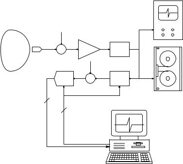
As shown in Figure 10.1, a modern biomedical instrumentation system generally includes a digital computer that is used to supervise, coordinate, and control the measurements, and which often is used to store (data logging), condition, and display data in a meaningful summary form on a monitor. In describing signal conversion interfaces, it is expedient first to consider digital-to-analog converters (DACs) because these systems are also used in the designs of several analog-to-digital converters (ADCs). Data conversion
391
© 2004 by CRC Press LLC
392 |
Analysis and Application of Analog Electronic Circuits |
|
DSO |
Q.U.M. |
n2 |
|
S |
||
|
x + n1 |
A |
S.C.F. |
|
|
|
|
|
n3 |
ADC |
|
A.A.F. |
A.T.R.
N
Computer
Sampling control
FIGURE 10.1
A typical instrumentation system. DSO = digital storage oscilloscope; ATR = analog tape recorder; SCF = signal conditioning filter (analog); AAF = anti-aliasing low-pass filter (analog); ADC = N-bit analog-to-digital converter under computer control; QUM = quantity under measurement.
from analog to digital form or digital to analog form is generally done periodically. Periodic data conversion has a great effect on the information content of the converted data, as will be shown next.
10.2.2The Sampling Theorem
The sampling theorem describes the analog filter required to recover an analog signal, x(t), from its impulse-modulated (sampled) form, x*(t). The theorem states that if the highest frequency present in the CFT of y(t) is fmax,
then when x(t) is sampled at a rate fs = 2 fmax, x(t) can be exactly recovered from x*(t) by passing x*(t) through an ideal low-pass filter, HIL(j2πf).
The weighting function (impulse response) of HIL(j2πf) is (Proakis and Manolakis, 1989):
hIL = |
sin(2πfmaxt) |
(10.1) |
|
(2πfmaxt) |
|||
|
|
© 2004 by CRC Press LLC
Digital Interfaces |
393 |
Thus, in the time domain, x(t) is given by the real convolution:
x(t) = x*(t) ƒ hIL(t) |
(10.2) |
The sampling rate, fs = 2 fmax, must be at least twice the highest frequency of the signal, x(t) to prevent aliasing. Note that many practical x(t)s can have spectra in which their RMS values approach zero asymptotically as f •. In this case, the Nyquist frequency can be chosen to be the value at which the RMS value of x(t) is some fraction of its maximum value, e.g., 1/103 or −60 dB.
Note that HIL(j2πf) is an ideal LPF and is not physically realizable. In practice, the sampling rate is made three to five times fmax in order to compensate for the finite attenuation characteristics of the real anti-aliasing low-pass filter and for any “long tail” on the spectrum of x(t). Even so, some small degree of aliasing is often present in X*(j2πf).
The sampling theorem is important because it establishes a criterion for the minimum sampling rate to be used to digitize a signal with a given low-pass power density spectrum. The relation between the highest significant frequency component in the signal’s power density spectrum and the sampling frequency is called the Nyquist criterion; the implications of this criterion and aliasing are discussed later.
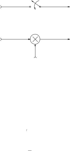
Because analog-to-digital data conversion is generally a periodic process, it is necessary first to analyze what happens when an analog signal, x(t), is periodically and ideally sampled. The ideal sampling process generates a data sequence from x(t) defined only and exactly at the sampling instants, when t = nTS, where n is an integer ranging from −• to +• and TS is the sampling period.
It is easy to show that an ideal sampling process is mathematically equivalent to impulse modulation, as shown in Figure 10.2. Here the continuous analog time signal, x(t), is multiplied by an infinite train of unit impulses or delta functions that occur only at the sampling instants. This multiplication process produces a periodic number sequence, x*(t), at the sampler output. In the frequency domain, X*(jω) is given by the complex convolution of X(jω) with the Fourier transform of the pulse train, PT(jω). In the time domain, the pulse train can be written as:
• |
|
PT (t) = δ(t − nTS ) |
(10.3) |
n= −•
The periodic function, PT, can also be represented in the time domain by a Fourier series in complex form:
• |
|
PT (t) = Cn exp(+ jωst) |
(10.4) |
n= –•
© 2004 by CRC Press LLC
394 |
Analysis and Application of Analog Electronic Circuits |
x(t) |
x*(t) |
|
Ts |
X(jω) |
X*(jω) = X(jω) PT (jω) |
∞
PT (t) = δ(t − nTs)
n = −∞
FIGURE 10.2
(A) A sampler equivalent of periodic analog-to-digital conversion. (B) An impulse modulator equivalent to a sampler.
where
ω = |
2π |
r s |
(10.5) |
s TS
and the complex-form Fourier series coefficients are given by the wellknown integral:
|
1 |
Ts |
2 |
|
1 |
Cn = |
|
|
|
PT (t)exp(− jωst)dt = |
|
T |
|
T |
|||
|
S −Ts |
2 |
|
S |
|
Thus, the complex Fourier series for the pulse train is found to be:
•
P (t) = 1 exp(+ jnω t)
T TS n= –• s
(10.6)
(10.7)
The sampler output in the time-domain is the product of PT (t) and x(t):
|
|
• |
|
x*(t) = x(t) |
1 |
exp(+ jnωst) |
(10.8) |
T |
|||
|
S n= –• |
|
|
© 2004 by CRC Press LLC

Digital Interfaces |
395 |
X(jω) X*(jω)
LPF
ω
− ωs − ωs /2 |
0 |
ωs /2 |
ωs |
3ωs /2 |
2ωs |
3ωs |
 X*(jω)
ω
− ωs |
− ωs /2 0 |
ωs /2 |
ωs |
3ωs /2 2ωs |
3ωs |
FIGURE 10.3
(A)The spectrum of a signal and spectrum of an ideally sampled signal that is not aliased.
(B)Spectrum of an aliased, sampled signal.
•
= 1 x(t)exp(+ jnω t)
TS n= –• s
The Fourier theorem for complex exponentiation is:
{ |
( |
+ jat |
)} |
∫ Y |
( |
jω − ja |
) |
(10.9) |
F |
y(t)exp |
|
|
|
Using this theorem, the Fourier transform for the sampler output can be written:
|
|
• |
|
X*(jω) = |
1 |
X(jω − jnωs ) |
(10.10) |
T |
|||
|
S n= –• |
|
|
Equation 10.10 for X*(jω) is the result of the complex convolution of X(jω) and PT(jω); it is in the Poisson sum form, which helps to visualize the effects of (ideal) sampling in the frequency domain, as well as to understand the phenomenon of aliasing. In Figure 10.3(A), the magnitude of X(jω) is plotted; note that X(jω) is assumed to have negligible power above the Nyquist frequency, ωs/2. When x(t) is sampled, a periodic spectrum for X*(jω) is seen.
As stressed earlier, x(t) can be recovered from the sampler output by passing x*(t) through an ideal low-pass filter, as shown in Figure 10.3(A). Figure 10.3(B) assumes that the base-band spectrum of x(t) extends beyond ωs/2. When such an x(t) is sampled, the resultant X*(jω) is also periodic, but the high frequency corners of the component spectra overlap. An
© 2004 by CRC Press LLC
396 |
Analysis and Application of Analog Electronic Circuits |
ideal low-pass filter thus cannot uniquely recover the base-band spectrum, so x(t). This condition of overlapping spectral components in X*(jω) is called aliasing; it can lead to serious errors in subsequent digital signal processing.
Because of the problem of aliasing, all properly designed analog-to- digital conversion systems used in FFT spectrum analyzers, time-frequency analyzers, and related equipment must operate on input signals that obey the Nyquist criterion, i.e., the power density spectrum of x(t), SXX(f), must have no significant power at frequencies above one half the sampling frequency. One way to ensure that this criterion is met is to use a properly designed analog low-pass anti-aliasing filter immediately preceding the sampler. According to Northrop (1990, Chapter 14):
Anti-aliasing filters are generally high-order linear phase LPFs that attenuate the input signal at least by 40 dB at the Nyquist frequency. Many designs are possible for high-order anti-aliasing filters. For example, Chebychev filters maximize the attenuation cut-off rate at the cost of some passband ripple. Chebychev filters can achieve a given attenuation cut-off slope with a lower order (fewer poles) than other filter designs. It should be noted that in the limit as passband ripple approaches zero, the Chebychev design approaches the Butterworth form of the same order, which has no ripple in the passband. Chebychev filters are designed in terms of their order, n, their cut-off frequency, and the maximum allowable peak-to-peak ripple (in decibels) of their passband.
If ripples in the frequency response stopband of an anti-aliasing filter are permissible, then elliptical or Cauer filter designs may be considered. With stopband ripple allowed, even sharper attenuation in the transition band than obtainable with Chebychev filters of a given order can be obtained. Elliptic LPFs are specified in terms of their order, their cutoff frequency, the maximum peak-to-peak passband ripple, and their minimum stopband attenuation.
Bessel or Thomson filters are designed to have linear phase in the passband. They generally have a “cleaner” transient response, that is, less ringing and overshoot at their outputs, given transient inputs.
One problem in the design of analog anti-aliasing filters to be used with instruments having several different sampling rates concerns adjusting the filters to several different Nyquist frequencies. One way of handling this problem is to have a fixed filter for each separate sampling frequency. Another way is to make the filters easily tunable by digital or analog voltage means. Some approaches to the tunable filter problem are discussed in Section 7.3 in Chapter 7 and in Chapter 10 of the text by Northrop (1990).
Anti-aliasing LPFs are generally not used at the inputs of digital oscilloscopes because one can see directly on the display if the sampled waveform is sampled too slowly for resolution. An optional analog LPF is often used to cut high-frequency interference on digital oscilloscope inputs; this, however, is not an anti-aliasing filter.
© 2004 by CRC Press LLC