

- •Analysis and Application of Analog Electronic Circuits to Biomedical Instrumentation
- •Dedication
- •Preface
- •Reader Background
- •Rationale
- •Description of the Chapters
- •Features
- •The Author
- •Table of Contents
- •1.1 Introduction
- •1.2 Sources of Endogenous Bioelectric Signals
- •1.3 Nerve Action Potentials
- •1.4 Muscle Action Potentials
- •1.4.1 Introduction
- •1.4.2 The Origin of EMGs
- •1.5 The Electrocardiogram
- •1.5.1 Introduction
- •1.6 Other Biopotentials
- •1.6.1 Introduction
- •1.6.2 EEGs
- •1.6.3 Other Body Surface Potentials
- •1.7 Discussion
- •1.8 Electrical Properties of Bioelectrodes
- •1.9 Exogenous Bioelectric Signals
- •1.10 Chapter Summary
- •2.1 Introduction
- •2.2.1 Introduction
- •2.2.4 Schottky Diodes
- •2.3.1 Introduction
- •2.4.1 Introduction
- •2.5.1 Introduction
- •2.5.5 Broadbanding Strategies
- •2.6 Photons, Photodiodes, Photoconductors, LEDs, and Laser Diodes
- •2.6.1 Introduction
- •2.6.2 PIN Photodiodes
- •2.6.3 Avalanche Photodiodes
- •2.6.4 Signal Conditioning Circuits for Photodiodes
- •2.6.5 Photoconductors
- •2.6.6 LEDs
- •2.6.7 Laser Diodes
- •2.7 Chapter Summary
- •Home Problems
- •3.1 Introduction
- •3.2 DA Circuit Architecture
- •3.4 CM and DM Gain of Simple DA Stages at High Frequencies
- •3.4.1 Introduction
- •3.5 Input Resistance of Simple Transistor DAs
- •3.7 How Op Amps Can Be Used To Make DAs for Medical Applications
- •3.7.1 Introduction
- •3.8 Chapter Summary
- •Home Problems
- •4.1 Introduction
- •4.3 Some Effects of Negative Voltage Feedback
- •4.3.1 Reduction of Output Resistance
- •4.3.2 Reduction of Total Harmonic Distortion
- •4.3.4 Decrease in Gain Sensitivity
- •4.4 Effects of Negative Current Feedback
- •4.5 Positive Voltage Feedback
- •4.5.1 Introduction
- •4.6 Chapter Summary
- •Home Problems
- •5.1 Introduction
- •5.2.1 Introduction
- •5.2.2 Bode Plots
- •5.5.1 Introduction
- •5.5.3 The Wien Bridge Oscillator
- •5.6 Chapter Summary
- •Home Problems
- •6.1 Ideal Op Amps
- •6.1.1 Introduction
- •6.1.2 Properties of Ideal OP Amps
- •6.1.3 Some Examples of OP Amp Circuits Analyzed Using IOAs
- •6.2 Practical Op Amps
- •6.2.1 Introduction
- •6.2.2 Functional Categories of Real Op Amps
- •6.3.1 The GBWP of an Inverting Summer
- •6.4.3 Limitations of CFOAs
- •6.5 Voltage Comparators
- •6.5.1 Introduction
- •6.5.2. Applications of Voltage Comparators
- •6.5.3 Discussion
- •6.6 Some Applications of Op Amps in Biomedicine
- •6.6.1 Introduction
- •6.6.2 Analog Integrators and Differentiators
- •6.7 Chapter Summary
- •Home Problems
- •7.1 Introduction
- •7.2 Types of Analog Active Filters
- •7.2.1 Introduction
- •7.2.3 Biquad Active Filters
- •7.2.4 Generalized Impedance Converter AFs
- •7.3 Electronically Tunable AFs
- •7.3.1 Introduction
- •7.3.3 Use of Digitally Controlled Potentiometers To Tune a Sallen and Key LPF
- •7.5 Chapter Summary
- •7.5.1 Active Filters
- •7.5.2 Choice of AF Components
- •Home Problems
- •8.1 Introduction
- •8.2 Instrumentation Amps
- •8.3 Medical Isolation Amps
- •8.3.1 Introduction
- •8.3.3 A Prototype Magnetic IsoA
- •8.4.1 Introduction
- •8.6 Chapter Summary
- •9.1 Introduction
- •9.2 Descriptors of Random Noise in Biomedical Measurement Systems
- •9.2.1 Introduction
- •9.2.2 The Probability Density Function
- •9.2.3 The Power Density Spectrum
- •9.2.4 Sources of Random Noise in Signal Conditioning Systems
- •9.2.4.1 Noise from Resistors
- •9.2.4.3 Noise in JFETs
- •9.2.4.4 Noise in BJTs
- •9.3 Propagation of Noise through LTI Filters
- •9.4.2 Spot Noise Factor and Figure
- •9.5.1 Introduction
- •9.6.1 Introduction
- •9.7 Effect of Feedback on Noise
- •9.7.1 Introduction
- •9.8.1 Introduction
- •9.8.2 Calculation of the Minimum Resolvable AC Input Voltage to a Noisy Op Amp
- •9.8.5.1 Introduction
- •9.8.5.2 Bridge Sensitivity Calculations
- •9.8.7.1 Introduction
- •9.8.7.2 Analysis of SNR Improvement by Averaging
- •9.8.7.3 Discussion
- •9.10.1 Introduction
- •9.11 Chapter Summary
- •Home Problems
- •10.1 Introduction
- •10.2 Aliasing and the Sampling Theorem
- •10.2.1 Introduction
- •10.2.2 The Sampling Theorem
- •10.3 Digital-to-Analog Converters (DACs)
- •10.3.1 Introduction
- •10.3.2 DAC Designs
- •10.3.3 Static and Dynamic Characteristics of DACs
- •10.4 Hold Circuits
- •10.5 Analog-to-Digital Converters (ADCs)
- •10.5.1 Introduction
- •10.5.2 The Tracking (Servo) ADC
- •10.5.3 The Successive Approximation ADC
- •10.5.4 Integrating Converters
- •10.5.5 Flash Converters
- •10.6 Quantization Noise
- •10.7 Chapter Summary
- •Home Problems
- •11.1 Introduction
- •11.2 Modulation of a Sinusoidal Carrier Viewed in the Frequency Domain
- •11.3 Implementation of AM
- •11.3.1 Introduction
- •11.3.2 Some Amplitude Modulation Circuits
- •11.4 Generation of Phase and Frequency Modulation
- •11.4.1 Introduction
- •11.4.3 Integral Pulse Frequency Modulation as a Means of Frequency Modulation
- •11.5 Demodulation of Modulated Sinusoidal Carriers
- •11.5.1 Introduction
- •11.5.2 Detection of AM
- •11.5.3 Detection of FM Signals
- •11.5.4 Demodulation of DSBSCM Signals
- •11.6 Modulation and Demodulation of Digital Carriers
- •11.6.1 Introduction
- •11.6.2 Delta Modulation
- •11.7 Chapter Summary
- •Home Problems
- •12.1 Introduction
- •12.2.1 Introduction
- •12.2.2 The Analog Multiplier/LPF PSR
- •12.2.3 The Switched Op Amp PSR
- •12.2.4 The Chopper PSR
- •12.2.5 The Balanced Diode Bridge PSR
- •12.3 Phase Detectors
- •12.3.1 Introduction
- •12.3.2 The Analog Multiplier Phase Detector
- •12.3.3 Digital Phase Detectors
- •12.4 Voltage and Current-Controlled Oscillators
- •12.4.1 Introduction
- •12.4.2 An Analog VCO
- •12.4.3 Switched Integrating Capacitor VCOs
- •12.4.6 Summary
- •12.5 Phase-Locked Loops
- •12.5.1 Introduction
- •12.5.2 PLL Components
- •12.5.3 PLL Applications in Biomedicine
- •12.5.4 Discussion
- •12.6 True RMS Converters
- •12.6.1 Introduction
- •12.6.2 True RMS Circuits
- •12.7 IC Thermometers
- •12.7.1 Introduction
- •12.7.2 IC Temperature Transducers
- •12.8 Instrumentation Systems
- •12.8.1 Introduction
- •12.8.5 Respiratory Acoustic Impedance Measurement System
- •12.9 Chapter Summary
- •References

Analog Active Filters |
|
|
|
|
301 |
R |
|
|
|
|
|
R |
|
|
|
|
|
R |
|
|
|
|
|
VS |
V2 |
V2’ 128 R |
R |
|
|
IOA |
|
A1 |
|
|
C |
|
|
|
|
V3 |
V3’ R |
|
|
R |
IOA |
A2 |
V4 = Vo |
|
|
WN1 |
|
|
IOA |
|
|
|
|
|
WN2
C
R V4’
A2
V5 IOA
FIGURE 7.16
In this digitally tuned biquad BPF, digitally controlled amplifier gains are used to set ωn and the Q.
V4 |
(ωn ) = −1 (peak gain) |
(7.60C) |
|
V |
|||
|
|
||
S |
|
|
Note that the A1 digitally controlled variable-gain amplifier drives a resistor of 128R so that the effective gain from V2 to V3 is (−A1/128). A1 values are typically (1, 2, 4, 8, 16, 32, 64, 128), so the BPF’s Q values are (128, 64, 32, 16, 8, 4, 2, 1). Thus, the digital word, WN2, can be used to scan the filter’s center frequency over a 1:128 range under constant Q conditions or the BPF’s
Qcan be adjusted independently with WN1.
7.3.3Use of Digitally Controlled Potentiometers To Tune a Sallen and Key LPF
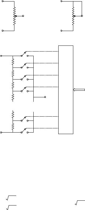
Digitally controlled potentiometers (DCPs) are IC devices based on the nMOS and CMOS transistor switch technology used in certain ADCs. Figure 7.17(A) illustrates the schematic of a simple analog (mechanical) potentiometer. Note that the potentiometer has three leads: two to the fixed resistor (CW and CCW) and the third (variable) connection called the wiper (W). In Figure 7.17(B), the potentiometer is connected as a variable resistor. Figure 7.17(C) illustrates a digitally programmed IC potentiometer. Only one MOS transistor switch is closed at a time connecting a node in the series resistor array to the wiper. The resistors are generally polycrystalline silicon deposited on an oxide layer for electrical isolation. They can have equal values (linear potentiometer) or be given values to approximate logarithmic attenuation.
Typically, DCPs have 256 (discrete) taps and thus an 8-bit serial input word is needed to select the wiper position. Like mechanical (analog) potentiometers, DCPs can be given the potentiometer (voltage divider) configuration
© 2004 by CRC Press LLC
302 |
Analysis and Application of Analog Electronic Circuits |
||
|
Potentiometer |
Variable resistor |
|
|
CW |
CW |
|
|
|
Analog pots |
|
|
Wiper |
|
|
|
W |
|
W |
|
CCW |
CCW |
|
|
A |
B |
|
|
MOS |
|
|
|
switches |
|
|
|
VH /RH |
|
|
|
R1 |
|
|
|
R2 |
|
|
|
R3 |
|
Digital |
|
Digital |
inputs |
|
|
|
||
|
|
|
|
|
|
controller |
|
|
|
“Wiper” |
|
|
|
VW /RW |
|
|
. |
. |
|
|
. |
. |
|
|
. |
. |
|
RN
VL /RL
C
FIGURE 7.17
(A) Schematic of a conventional mechanically tuned analog potentiometer. (B) A potentiometer connected as a variable resistor. (C) A digitally programmed analog potentiometer. Only one MOS switch is closed at a time. An 8-bit digital pot has 256 taps.
or be used as variable resistances. Manufacturers of DCPs include Analog Devices, Maxim, and Xicor.
A DCP connected as a variable resistor can be used to set an AF’s filtering parameters (ωn, gain, and Q or damping). Figure 7.18 illustrates the use of two DCPs (with the same control input) to tune an S & K LPF at constant damping by varying R. Recall that the natural frequency of an S & K LPF’s poles is at ωn = 1/(R C1 C2) r/s, and its damping factor is solely determined by the square root of the ratio of the capacitors; e.g., ξ = C2 C1. Thus, for this LPF, ωn = 1/(Rdp C1 C2) r/s. Note that ωn varies hyperbolically with Rdp.
© 2004 by CRC Press LLC

Analog Active Filters |
|
|
303 |
|
C1 |
|
|
Rdp |
|
Rdp |
V2 |
VS |
|
|
|
V1 |
|
Vo |
|
|
|
||
|
|
IOA |
|
|
|
|
C2 |
WN
N
Rdp = Rtotal Σ Bk 2k −(1 + N) k = 1
Bk = 0,1
N = 8
FIGURE 7.18
A pair of digitally controlled potentiometers are used as variable resistors in a digitally tuned Sallen and Key low-pass filter.
Many examples exist of electronically tuned AFs (see Chapter 10 in Northrop, 1990). Analog voltages or currents derived from DACs, or serial or parallel digital words can be used to set resistors or gains in DCVGEs. (A classic example of adaptive filter design is the venerable Dolby B‘ audio noise reduction system; this system is treated in detail in Chapter 10 of Northrop (1990)).
7.4Filter Applications (Anti-Aliasing, SNR Improvement, etc.)
Most analog active filters used in biomedical signal conditioning are intended to restrict the amplifier pass band to that of the signal spectrum, thereby cutting off broadband noise outside the signal spectrum and improving the signal-to-noise ratio at the filter output over that at the input to the signal conditioning system. Another major application of active filters is antialiasing, i.e., attenuating signal and noise power at the input to an analog- to-digital converter to a negligible level at frequencies of half the sampling frequency and greater.
In modern ECG and EEG data acquisition systems, one often finds an optional notch filter that can be used to attenuate coherent interference (hum) at line frequency (60 Hz). All-pass filters are used to generate a phase shift between the input and output signal without attenuation. These filters are
© 2004 by CRC Press LLC