

- •Preface
- •Acknowledgments
- •Contents
- •Contributors
- •1. Introduction
- •2. Evaluation of the Craniomaxillofacial Deformity Patient
- •3. Craniofacial Deformities: Review of Etiologies, Distribution, and Their Classification
- •4. Etiology of Skeletal Malocclusion
- •5. Etiology, Distribution, and Classification of Craniomaxillofacial Deformities: Traumatic Defects
- •6. Etiology, Distribution, and Classification of Craniomaxillofacial Deformities: Review of Nasal Deformities
- •7. Review of Benign Tumors of the Maxillofacial Region and Considerations for Bone Invasion
- •8. Oral Malignancies: Etiology, Distribution, and Basic Treatment Considerations
- •9. Craniomaxillofacial Bone Infections: Etiologies, Distributions, and Associated Defects
- •11. Craniomaxillofacial Bone Healing, Biomechanics, and Rigid Internal Fixation
- •12. Metal for Craniomaxillofacial Internal Fixation Implants and Its Physiological Implications
- •13. Bioresorbable Materials for Bone Fixation: Review of Biological Concepts and Mechanical Aspects
- •14. Advanced Bone Healing Concepts in Craniomaxillofacial Reconstructive and Corrective Bone Surgery
- •15. The ITI Dental Implant System
- •16. Localized Ridge Augmentation Using Guided Bone Regeneration in Deficient Implant Sites
- •17. The ITI Dental Implant System in Maxillofacial Applications
- •18. Maxillary Sinus Grafting and Osseointegration Surgery
- •19. Computerized Tomography and Its Use for Craniomaxillofacial Dental Implantology
- •20B. Atlas of Cases
- •21A. Prosthodontic Considerations in Dental Implant Restoration
- •21B. Overdenture Case Reports
- •22. AO/ASIF Mandibular Hardware
- •23. Aesthetic Considerations in Reconstructive and Corrective Craniomaxillofacial Bone Surgery
- •24. Considerations for Reconstruction of the Head and Neck Oncologic Patient
- •25. Autogenous Bone Grafts in Maxillofacial Reconstruction
- •26. Current Practice and Future Trends in Craniomaxillofacial Reconstructive and Corrective Microvascular Bone Surgery
- •27. Considerations in the Fixation of Bone Grafts for the Reconstruction of Mandibular Continuity Defects
- •28. Indications and Technical Considerations of Different Fibula Grafts
- •29. Soft Tissue Flaps for Coverage of Craniomaxillofacial Osseous Continuity Defects with or Without Bone Graft and Rigid Fixation
- •30. Mandibular Condyle Reconstruction with Free Costochondral Grafting
- •31. Microsurgical Reconstruction of Large Defects of the Maxilla, Midface, and Cranial Base
- •32. Condylar Prosthesis for the Replacement of the Mandibular Condyle
- •33. Problems Related to Mandibular Condylar Prosthesis
- •34. Reconstruction of Defects of the Mandibular Angle
- •35. Mandibular Body Reconstruction
- •36. Marginal Mandibulectomy
- •37. Reconstruction of Extensive Anterior Defects of the Mandible
- •38. Radiation Therapy and Considerations for Internal Fixation Devices
- •39. Management of Posttraumatic Osteomyelitis of the Mandible
- •40. Bilateral Maxillary Defects: THORP Plate Reconstruction with Removable Prosthesis
- •41. AO/ASIF Craniofacial Fixation System Hardware
- •43. Orbital Reconstruction
- •44. Nasal Reconstruction Using Bone Grafts and Rigid Internal Fixation
- •46. Orthognathic Examination
- •47. Considerations in Planning for Bimaxillary Surgery and the Implications of Rigid Internal Fixation
- •48. Reconstruction of Cleft Lip and Palate Osseous Defects and Deformities
- •49. Maxillary Osteotomies and Considerations for Rigid Internal Fixation
- •50. Mandibular Osteotomies and Considerations for Rigid Internal Fixation
- •51. Genioplasty Techniques and Considerations for Rigid Internal Fixation
- •52. Long-Term Stability of Maxillary and Mandibular Osteotomies with Rigid Internal Fixation
- •53. Le Fort II and Le Fort III Osteotomies for Midface Reconstruction and Considerations for Internal Fixation
- •54. Craniofacial Deformities: Introduction and Principles of Management
- •55. The Effects of Plate and Screw Fixation on the Growing Craniofacial Skeleton
- •56. Calvarial Bone Graft Harvesting Techniques: Considerations for Their Use with Rigid Fixation Techniques in the Craniomaxillofacial Region
- •57. Crouzon Syndrome: Basic Dysmorphology and Staging of Reconstruction
- •58. Hemifacial Microsomia
- •59. Orbital Hypertelorism: Surgical Management
- •60. Surgical Correction of the Apert Craniofacial Deformities
- •Index
60
Surgical Correction of the Apert Craniofacial Deformities
E. Clyde Smoot, III and William L. Hickerson
Apert Syndrome
Apert first utilized the term acrocephalosyndactyly in 1906 to describe a foreshortened, tower-shaped cranial malformation associated with syndactyly of all four extremities. Just over 300 such patients have been described in the literature. The syndrome occurs in 1 in 160,000 live births. More recently, Cohen utilized an indirect method and showed that Apert syndrome represented 4% of all the cases of craniosynostosis for 13.7 cases per 1,000,000 live births.1,2
Cohen examined the skeletal abnormalities in Apert syndrome and reported x-ray evidence of multiple epiphyseal dysplasia. He found decreased mobility at the glenohumeral joint, a shortened humerus, limited elbow mobility, radiohumeral synostosis, spine changes with vertebral fusion, spina bifida, scoliosis, and hip abnormalities. These changes were associated with bony fusion of the hands and feet causing a complex syndactyly (or mitten) hand deformity. Associated visceral anomalies are not common, but cardiovascular abnormalities are found in 10% of the patients and genitourinary anomalies are also reported as frequently. Multiple ocular abnormalities are diagnosed in these patients and include optic atrophy, cataracts, iris and chorodial colobomas, keratoconus, medulated nerve fibers, and bilateral superior oblique nerve palsy.3–7
In planning staged surgical interventions for improvement of the craniofacial anomalies associated with Apert syndrome, it is important to understand the anatomic pathology and to consider the etiopathogenesis of the deformities.8 The newborn Apert child has anterior fontanelles that are widely open, extending to the inferior extent of the metopic suture. The head appears hyperacrobrachycephalic, and there is flattening of the occipital region. The steep forehead is associated with a prominent bregma, and in some cases a transverse groove is apparent above the supraorbital ridge. Exorbitism and midfacial hypoplasia may be marked. As the patient ages a relative prognathism is appreciated and the nasal bridge is depressed. The nose may lack tip support and have a beaked appearance.
The cranium in Apert syndrome undergoes premature fusion of the coronal sutures with the remaining sutures patent at birth. Kreiborg et al. reported that abnormalities in the cartilage of the anterior cranial base during early intrauterine life may play a major role in the formation of the misshapen skull. These authors further showed that the cranial vault development underwent a progressive fusion with age. The intracranial volume in these syndromic patients is normal at birth but increases to become 3 standard deviations (SD) above normal after 6 months of age. Although intracranial pressure is usually not increased in these patients as the result of the large midline calvarial defect, early release of the coronal sutures and advancement of the frontal bone is advocated to decrease the dysmorphic changes in the calvaria and cranial base.9,10
Radiologic studies of the Apert skull will demonstrate fusion of the coronal sutures to the cranial base. At birth, however, these patients appear to have patent sphenozygomatic and sphenotemporal sutures. Lambda is patent as is the occipitomastoid suture. The zygomatic process of the frontal bone is hypoplastic, and the cranial base may be malformed and asymmetric. The anterior fossa tends to be short, as are the orbits. With time the ethmoids may become expansive. As head growth proceeds, there will be increased bitemporal head width secondary to compensatory growth of a megalencephalic brain pushing and directing growth at the squamosal sutures. The temporalis muscles may be short and inferiorly positioned. Other gross features of the facial region reveal a high arched narrow palate, which may or may not be associated with a cleft of the soft palate. With aging, the patient’s skin becomes abnormally thick, thus affecting the soft tissue envelope that reflects the underlying bony abnormalities. By early adolescence severe seborrhea and acne may be present on the head, neck, trunk areas, along the upper extremities.8,11
The etiology of the bony abnormalities remains speculative, but there are substantial radiologic data and fetal cadaver studies to support a cranial-based abnormality related to dysostosis of the midline cranial structures, a hypoplastic anterior cranial base, and associated hypoplasia of the maxillary
749
750
complex. Using a rabbit model, Persing et al.12 have developed an alternate explanation of growth disturbance to indicate growth arrested at multiple sutures in the cranial vault may produce complex craniofacial abnormalities similar to Apert deformity. This supports theories that growth abnormalities need not necessarily be localized to the cranial base.12
There is a broad range of phenotypic expression of the Apert disease. It is helpful for the surgeon to recognize, with the family, that a surgical correction may improve the patient’s appearance and function but that Apert patients never achieve normal facial appearance. There is usually some residual element of calvarial asymmetry, orbital hypertelorism, proptosis, or midface deficiency when compared to other patients who have undergone surgery for correction of brachycephalic conditions. Even the expression of the forehead frontal calvaria deformity may be variable. Tessier has described the turricephalic type of deformity, which results in a predominant, tower-shaped skull. Hyperbrachycephalic abnormalities result in abnormally wide, short skulls. A third variant is that of patients presenting with a median, vertical, frontal gibbosity or a frontal keel-type deformity.13
Posnick has addressed the issue of residual cranial skull base and forehead deformity after forehead advancement and remodeling. Quantitative postoperative computed tomography (CT) scan assessment after cranial and orbital reshaping and advancement indicate change. However, no significant quantitative improvement is noted when compared to agematched controls. Early surgery of the anterior skull base and cranium did not normalize subsequent growth for the patients with Apert disease.14
Failure of sustained qualitative improvement of the operated craniofacial features is recognized likewise. After forehead advancement there may be unpredictable skull growth with additional turricephalic deformity and ridging above the supraorbital band. Incomplete reossification of the forehead region can occur even with properly performed advancements. The less than predictable results that are obtained with cranial reshaping and midface advancements, and the inability to normalize facial appearance, have been disheartening for many experienced craniofacial surgeons.15
Other surgeons have been less discouraged. Despite the incomplete understanding of the pathophysiology of the disease process and the apparent incomplete technology of the surgical capabilities that exist in the field, surgical interventions are worthwhile for improvement. The goals of correcting skeletal and soft tissue defects in these patients are to correct facial appearance, improve function, and preserve vision. Deformities that interfere with vision require timely surgical interventions to prevent amblyopia. Midface advancement for relief of nasopharyngeal obstruction or to correct malocclusion are also achievable goals in these patients. For the occasional patient who does have increased intracranial pressure, forehead advancement may enlarge the cranial vault. However, correction of increased intracranial pressure with shunting may still be required in some cases.6,16,17
E.C. Smoot, III and W.L. Hickerson
Evaluation of the Apert Patient
Because of midface hypoplasia associated with the dental alveolar deformities in these patients, an open-mouth posture may be present with some element of choanal atresia. A short, hard palate is often seen with a long, soft palate, which may be cleft. The maxillary dental arch will appear as a V-shape with downslanting of the posterior portion of the maxilla. There may be enlargement of the alveolar ridges as the patient ages. Airway problems are frequent in these patients and may consist of upper-airway obstruction, with a small pharynx, and associated lower-airway problems including tracheomalacia and bronchomalacia. It is important when evaluating young patients with CT scans that sedation be done only with careful monitoring of the airway while ensuring oxygenation.18
Ferraro has reported cervical spine deformities in these patients with intervertebral fusions of the C-5 to C-6 region. Complex and extended fusions that restrict the flexion and extension of the neck must be anticipated. There are reports of C-1 to C-2 subluxation. A careful evaluation of the neck before the positioning for anesthesia or manipulations for sleep apnea is necessary.
Besides spinal deformities, epiphyseal dysplasia in these patients may result in problems with decreased elbow flexion and shoulder range of motion. A genu valgus deformity may be present. These abnormalities must be appreciated when preparing patients for surgery. Any limitation must be conveyed to operating room personnel so that appropriate positioning precautions are undertaken. The complex syndactylies of the hands require surgical intervention to obtain useful hand function. These deformities need attention from the appropriate surgical specialist as a part of the comprehensive evaluation of the patient.4
Although not a common sequela of this disease process, increased intracranial pressure may occur either before or after forehead advancement and may require shunt decompression. Despite the apparent patent lambdoidal, squamosal, and midline sutures, the calvarial deformity of the Apert patient can result in increased intracranial pressure. This may be secondary to the megacephalic brain and dysmorphic brain growth within a hyperbrachycephalic calvarial vault.
Infants with Apert disease may have exorbitism, which is relieved with an initial 12to 15-mm advancement of the forehead and supraorbital bandeau. These patients need to be observed for corneal exposure and keratitis. Associated abnormalities of blepharoptosis, downslanting palpebral fissures, strabismus, and ametropia all need to be evaluated by an ophthalmologist or an oculoplastic surgeon so that early correction of visual disturbances is undertaken. Amblyopia is often a preventable cause of visual loss. It was the most common reason for blindness in one series of Apert patients who were studied for visual defects. Papilledema from nerve compression was rarely a cause of visual loss.6
Besides the obvious upper-airway problems that may oc-
60. Surgical Correction of Apert Craniofacial Deformities
cur in Apert patients, additional concerns with snoring and sleep apnea may warrant evaluation with cardiopulmonary polysonography. Infants with initial respiratory distress may improve as they grow. Respiratory symptoms may recur by 2 to 3 years of age when tonsils and adenoids begin to enlarge. However, in these patients the removal of tonsils and adenoids, or even midface advancement, at the age of 4 may not relieve the apnea, which can result from tracheomalacia or bronchomalacia. Therefore, patients with suspected anomalies of the respiratory region warrant magnetic resonance imaging (MRI) of the trachea to exclude other abnormalities such as a solid, cartilaginous trachea and tracheal stenosis.19,20
Dental hygiene in these patients is important as teeth erupt. Any surgical interventions that require dental fixation can be better performed if the teeth are without decay and soft gum tissues are healthy. Because of restricted hand function it may be difficult for patients to floss and brush their teeth. Parental assistance or devices to help with tooth brushing and flossing need to be provided to the patient. Routine dental prophylaxis with the use of fluoride sealing of the teeth is important.18
Operative Intervention
Forehead advancement for decompression of the intracranial space, protection of the globes, and construction of a normalappearing supraorbital band is usually performed between 3 and 6 months of age. Before that time, the bone is too soft for reshaping and fixation. A 12to 15-mm advancement done before 6 months of age may take advantage of the remaining growth potential of the frontal lobes. The bone segments at that time are easy to manipulate. Working through a coronal incision, the temporalis muscles are detached. Because the metopic sutures are patent, the frontal bone segments are independently raised. This procedure is performed at the initial frontal craniotomy and before supraorbital advancement. The fused coronal sutures are released, and no interpositional materials are used in the coronal suture craniectomy. The nasal bones may be advanced with the forehead bandeau as an extended procedure. More commonly, a supraorbital band is developed independent of the nasal bones.8
Posnick is an advocate of reshaping of the supraorbital contour in addition to advancement. A bandeau as a tenon and temporal groove is fashioned laterally with a step cut at the frontal zygomatic area. The bandeau segment is freely mobilized for manipulations. This technique allows bending of the bone to decrease the bitemporal width and create more convexity in the anterior midline. The bandeau can be replaced and held in its advanced position. When the forehead is redraped over the advanced segments, the flap may be tight. Rigid fixation of the advanced supraorbital region at the lateral tongue and groove osteotomy sites may prevent relapse of the advanced forehead segment under a restrictive flap. Bone grafts wedged along the osteotomy floor of the anterior
751
fossa will also help maintain the forward projection. It is better that the advanced segments be stabilized without plate fixation across any released suture sites. If a fracture of the supraorbital bandeau occurs with attempts at reshaping the segment, a long microplate may be used to join the segments and allow additional bending and shaping.14
Rigid fixation should be minimized and the smallest plates that achieve three-dimensional stability should be employed (Figures 60.1 and 60.2). In cases where longer plates may be necessary to stabilize fractured segments or areas of bone that require extensive reshaping, then it is appropriate to plan for early removal of these plates after initial bony union. If adequate stability can be achieved with resorbable plates, this will avoid the need for plate removal. The frontal bone segments are reattached to the supraorbital bandeau and the temporalis muscles are advanced to the frontal bone segment. Lateral canthopexies are also performed.
In situations of excessive bitemporal width, the squamous portion of the temporal bone can be removed in the infant and will reossify with less convexity. For cases of more extreme turribrachycephaly, lateral barrel stave osteotomies may be performed to decompress the temporal lobes and allow lateral redistribution of the brain. Future growth in these sites, however, is not predictable with any of these surgical manipulations done at this early age. There is no proven benefit for extending frontal suture craniectomies into the skull base despite concerns that the Apert disease process may involve this area.8,13
A monobloc advancement of the forehead and midface in infancy has been described for extreme cases of exorbitism and airway obstruction. Unfortunately this operation carries a 33% infection rate, which may result in loss of the frontal bone, possible meningitis, and occasionally death. Therefore, the morbidity and mortality rates associated with this operation preclude its use except in extraordinary instances during infancy. Exorbitism at an early age can usually be managed
FIGURE 60.1. Rigid fixation of the advanced forehead and frontal bone segments will resist the tendency for relapse with coronal flap closure. The bone plates chosen for use along limited sites should be small but should provide three-dimensional stability. Plates are not used across suture lines.
752
FIGURE 60.2. Rigid fixation of the advanced supraorbital bandeau at the tenon allows resistance to displacement when the coronal flap is redraped and closed.
with a forehead advancement and lateral tarsorraphies if necessary.
Eyelid deformities may occur with orbital surgery or may be a part of the primary disease process. Contour irregularities, lid ptosis, nasolacrimal obstruction, or altered ocular muscle imbalance may create conditions of amblyopia. These orbital conditions require concomittant assessment and correction. While the majority of Apert patients have an interorbital distance that exceeds the 97th percentile, those who have true orbital hypertelorism may require orbital translocation as a separate procedure. Partition of a monoblock advancement has been done for partial correction but is not advisable for reasons of high risk of infection.19,21
Despite well-executed surgery to advance the forehead and to correct increased bitemporal width, growth in the postoperative period during the first 6 years of life may not be predictable. Excess vertical growth and contour deformities of the forehead and temporal fossa may become apparent. Forehead advancement does not normalize growth. Cases of severe residual deformity may necessitate readvancement of the forehead before age 6. Beyond that age, with the development of the frontal sinus, a forehead advancement carries a high risk of infection. Therefore, if a forward advancement is planned after the age of 6, the surgeon must ensure that the frontal sinuses are obliterated and the ducts occluded to prevent a route for infection from the nasal region. Some surgeons will not advance the forehead after 6 years of age. Correction of forehead and temporal fossa deformities in older patients may be undertaken with onlay bone grafts or with the use of alloplastic materials such as methylmethacrylate.15
E.C. Smoot, III and W.L. Hickerson
Respiratory problems in the Apert infant can be quite severe. Midface advancement in the first year is not indicated except in rare situations of respiratory distress. Tracheostomy is preferable to midface advancement in those less than 4 years of age. If positioning is successful in overcoming airway obstruction of the lungs, then the child must be watched for problems with respiratory distress as the adenoids and tonsils enlarge. In some cases early intervention to remove enlarged tonsils and adenoids may be necessary before any contemplation of a midface advancement.12 For those patients who have a cleft palate with associated respiratory distress and a small nasopharynx, repair of the palate may need to be delayed. Because of the long palate and short nasopharynx, hypernasality may not be readily apparent in patients with a soft palatal cleft.8,16,22
As the child grows, continued problems with the upper airway may produce sleep apnea. A Le Fort III advancement performed as an extracranial procedure may be necessary by 4 years of age. Reoccurrence of exorbitism with exposure of the globes is possible and will be improved with midface advancement at this early age. If midface retrusion is mild and psychosocial issues are not pressing, a Le Fort III advancement may better serve the child as a one-stage procedure done between 9 and 12 years of age. Early midface advancement by age 4 does not normalize facial growth; however, it may relieve upper-airway obstruction and protect the globes for patients with the most severe deformities. Le Fort III advancement done in the early childhood period will not result in longterm improvement of occlusion. In those cases, the parents and patients must be prepared for additional orthognathic surgery in the later adolescent years to correct occlusion.16,23
The Le Fort III advancement is done as an extracranial procedure to avoid the attendant risk of intracranial infection. Osteotomies with spur cuts to the sphenozygomatic sutures are planned. Careful osteotomies and gentle pterygomaxillary disimpaction help to to avoid irregular fracture patterns. An overcorrected, advanced position can then be stabilized with miniplates at the lateral orbits and above the nasal bones. Bone grafts along the defects of the bony advancement sites, exclusive of the pterygomaxillary sites, are placed to help stabilize the advancement (Figures 60.3 and 60.4). In cases in which exorbitism is to be corrected, it may be necessary to incise and release the periorbita to allow expansion of the soft tissue contents into the expanded orbital cavity. In these cases bone grafts to the floor of the advanced orbit are necessary to avoid enophthalmus from prolapse of the orbital contents into the underlying sinus.13
Patients of 4 years and older may require early midface advancement and forehead readvancement. Procedures are staged separately to avoid concomitant intracranial and intraoral exposure. It is tempting to proceed with a monobloc advancement of the forehead and midface, if exorbitism is present and the position of the supraorbital bandeau and forehead correction are not satisfactory after an initial surgery. Infection risk and potential forehead bone loss, however, dictate
60. Surgical Correction of Apert Craniofacial Deformities
FIGURE 60.3. For the young patient undergoing a Le Fort III, the advancement can be stabilized with bone plates along the lateral orbits and above the nasal bones. Bone grafts placed along the nasal orbital and zygomatic osteotomy sites provide additional stability and maxillomandibular fixation can be omitted.
avoiding a monobloc procedure. In most cases, there are different requirements for the amount of advancement of the forehead and midface. Differential advancement cannot be achieved with a monobloc procedure. In patients who require forehead readvancement it is preferable to allow healing of the forehead procedure before a midface advancement staged as a separate operation.15,19
In adolescence, Apert patients will require expansion of the narrow V-shaped palatal structures, presurgical orthodontics, and planning for orthognathic surgery as growth is completed. At a minimum, most of these patients will require a Le Fort I advancement to correct occlusion. Setback of the mandible may be necessary for large occlusal discrepancies. Extreme caution is necessary in planning these procedures for patients who have a small oral pharynx as this may allow the tongue to occlude the airway. The mandibular surgery is usually reserved until completion of mandibular growth at 18 to 20 years of age. Segmental osteotomies of the occlusal segments may be necessary for correction of some maxillary deformities.18
Intheteenageyears,finaltouchupandadjustmentsoftheforehead, temporal fossa, and supraorbital ridges may require bone grafting with rigid fixation or the use of alloplastic materials in the sites along the forehead. Nasal surgery can also be completed in the teenage years. Dorsal support with cantilever rib grafting fixed rigidly may improve the appearance of the nose.
753
FIGURE 60.4. Despite early forehead cranioplasty and advancement, additional growth abnormalities of the forehead region often result in deformities that require further correction in the adolescent patient.
Rigid Fixation of Osteotomies
The use of rigid plate fixation for stabilizing osteotomies in the growing craniofacial skeleton remains controversial. There are a number of reports indicating problems with relative migration of the plates and screws toward the dura with cranial growth. Bone resorption and deposition may allow the cranial plate to ultimately come to rest along the inner cranial cortex. Additional problems can occur with resorption around the plates, causing plate prominence, or even plates or screws isolated on a peninsula of bone along the outer cortex. Large plates may be a problem under thin skin because of visibility or palpable irregularities along the face and skull. Resorbable miniplates have become available and increasing in use, with the advantage of not requiring removal. However, resorbable plates may not provide adequate stability in large movements and titanium plates allow superior fixation in these circumstances.24,25 Alternative methods for bone fixation include wire osteosynthesis or stabilization with sutures such as 4-0 Prolene. For frontal bone segments that are repositioned without significant stress forces, the use of cranial bone wedged along the advanced anterior fossa may provide stability to the repositioned supraorbital bandeau and forehead.26
Rigid plates do have a role in providing three-dimensional stability for bony segments that have been advanced and will need to resist force during the closure and in the postopera-
754
tive period. The properly chosen microor miniplate provides stability of the forehead and can be placed along a tongue- and-groove osteotomy to resist the tendency toward relapse that may occur with closure of a tight coronal flap. T-shaped microplates used to stabilize the bifrontal forehead bone grafts to the supraorbital bandeau will help retain the position of these bone segments against tight flap closure. The plates should not be placed across the coronal suture lines or along other sutures or growth regions. All bone fixation techniques when employed across open suture lines have resulted in some growth interference. The rigid plates, however, contribute the most to growth disturbance.
Rigid fixation of the advanced midface during childhood provides stability necessary to avoid maxillomandibular fixation. There is an additional benefit of allowing easier airway management without the need for tracheostomy in these young patients who have a small pharynx. A trend toward less skeletal relapse of the advanced midface with use of the fixation plates has been noted. However, it has not been established that rigid fixation of a Le Fort osteotomy prevents relapse.
An additional indication for use of screw or plate fixation is in the application of onlay bone grafts. Cranial bone, used for correction of forehead contours in the later years or rib for cantilever grafting of the nose, can be stabilized with plates and screws to ensure the position and avoid migration. The benefits of rigid fixation of onlay bone grafts resulting in less bone resorption are well established.
Fixation plates are easy to use and provide stability that cannot be achieved with other techniques of osteosynthesis. At this point there are no proven cases of brain injury resulting from plate migration. The plates, when used judiciously and in a limited fashion along appropriate areas, can assist with healing of the bone segments in their corrected position. If there is concern with the plates, they can be removed 3 months after the procedure. Long-term histocompatibility of the plates has not been established, nor have there been studies of long-term effects of corrosion. There are problems with roentgenographic scatter and artifact when these patients undergo postoperative radiographs. Titanium plates allow for the best radiographic visualization and are tolerated during MRI scanning without plate or screw loosening.
Plates should be carefully chosen and used in minimal quantities to achieve the stabilization required. They should not be used across suture lines, and they should not be applied to the inner surface of the cranial vault. They serve an important function, extending the surgeon’s ability to reshape the cranial and facial skeleton in the growing Apert patient.
Overview of Surgical Management
Surgical correction of the multiple craniofacial anomalies of the growing Apert child is worthwhile in improving the appearance and function of the patient. The initial forehead cranioplasty to advance the anterior cranial base and protect the
E.C. Smoot, III and W.L. Hickerson
globes will improve the appearance of the patient. Unfortunately, it is not possible to obtain a normal face in these patients. Even with extended suture release along the anterior base, growth deformities of the cranial base and the midface still occur. The forehead advancement and reshaping of the cranial orbitozygomatic region at a young age does not normalize growth of the cranium. There are inherent growth abnormalities in the forehead region. In the presence of a megalencephalic brain deformity, unpredictable skull growth and shape changes may occur after properly performed forehead advancement, resulting in additional turricephalic abnormalities. Repeat surgical procedures may be required to correct the forehead and orbital appearance.
Despite early forehead advancement, there does not seem to be a positive benefit resulting in midface growth. Midface advancement as a Le Fort III osteotomy can be done with relative safety in the patients older than 4 years if there is a functional need for airway enlargement or need to protect the globes. Early intervention for midface advancement may also be indicated where there is severe deformity causing psychological disease. The advancement can be done obtaining segment stability, but there has been no benefit in promoting further anterior or downward growth with the repositioning even after overcorrection. It must be anticipated that the patient will require additional surgery either as a readvanced Le Fort III segment or a Le Fort I osteotomy to correct occlusion in the teenage years. Midface advancement while useful at an early age for enlarging the airway may not necessarily correct sleep apnea in the Apert patient because of associated lower-airway abnormalities, including tracheomalacia and bronchomalacia.
The utilization of rigid fixation with plates and screws definitely has its advantages, especially when bicoronal flap closure is tight over the advanced segments. Plates should be used under the conditions described here. Plate removal after 3 months has been recommended by some surgeons, although this is as controversial as the utilization of the plates themselves. With the development of absorbable plates and screws, concerns regarding cranial growth restriction and plate removal should be alleviated.24,25
References
1.Kaplan LC. Clinical assessment and multispecialty management of Apert syndrome. Clin Plast Surg. 1991;18:217.
2.Cohen MM Jr, Kreiborg S. New indirect method for estimating the birth prevalence of the Apert syndrome. J Oral Maxillofac Surg. 1992;21:107–109.
3.Cohen MM Jr, Kreiborg S. Growth pattern of the Apert syndrome. Am J Med Genet. 1993;47:617–623.
4.Cohen MM Jr, Kreiborg S. Skeletal abnormalities in the Apert syndrome. Am J Med Genet. 1993;47:624–632.
5.Cohen MM Jr, Kreiborg S. Visceral anomalies in the Apert syndrome. Am J Med Genet. 1993;45:758–760.
6.Hertle RW, Quinn GE, Minguini N, Katowitz JA. Visual loss
60. Surgical Correction of Apert Craniofacial Deformities
in patients with craniofacial synostosis. J Pediatr Ophthalmol Strabismus. 1991;28(6):344–349.
7.Pollard ZF. Bilateral superior oblique muscle palsy associated with Apert syndrome. Am J Ophthalmol. 1988;106:337–340.
8.Mulliken JB, Bruneteau RJ. Surgical correction of the craniofacial anomaliesinApertsyndrome.Clin Plast Surg. 1991;18(2):277–289.
9.Kreiborg S, Marsh JL, Cohen MM Jr, Liversage M, Pedersen H, Skovly F, Borgesen SE, Vannier MW. Comparative three dimensional analysis of CT scans of the calvaria and cranial base in Apert and Crouzon syndromes. J Cranio-Maxillofac Surg. 1993;21:181–188.
10.Gosain AK, McCarthy JG, Glatt P, Staffenberg D, Hoffman RG. A study of intracranial volume in Apert syndrome. Plast Reconstr Surg. 1994;95(2):284–295.
11.Cohn MS, Mahon MJ. Apert syndrome (acrocephalosyndactyly) in a patient with hyperhidrosis. Cutis. 1993;52:205–208.
12.Persing JA, Lettieri JT, Cronin AJ, Putnam W, Wolcott BS, Singh V, Morgan AB. Craniofacial suture stenosis morphologic effects. Plast Reconstr Surg. 1990;88:563–571.
13.Marsh JL, Galic M, Vannier MW. The craniofacial anatomy of Apert syndrome. Clin Plast Surg. 1991;18(2):237–248.
14.Posnick JC, Lin KY, Jhawar BJ, Armstrong D. Apert syndrome: quantitative assessment by CT scan of presenting deformity and surgical results after first-stage reconstruction. Plast Reconstr Surg. 1994;93(3):489–497.
15.Marsh JL, Miroslav G, Vannier MW. Surgical correction of the craniofacial dysmorphology of Apert syndrome. Clin Plast Surg. 1991;18:251–275.
16.McCarthy JG, LaTrenta GS, Breitbart AS, Grayson BH, Bookstein FL. The Le Fort III advancement osteotomy in the child under seven years of age. Plast Reconstr Surg. 1990;86(4):633–649.
755
17.Ferraro NF. Dental, orthodontic, and oral/maxillofacial evaluation and treatment in Apert syndrome. Clin Plast Surg. 1991; 18(2):291–307.
18.Marchac D, Renier D, Broumand S. Timing of treatment for craniosynostosis and faciocraniosynostosis: a 20-year experience. Br J Plast Surg. 1994;2:211–222.
19.Mixter RC, David DJ, Perloff WH, Green CG, Pauli RM, Popec PM. Obstructive sleep apnea in Aperts and Pfeiffer syndromes. Plast Reconstr Surg. 1990;86(3):457–463.
20.Posnick JC, Waitzman A, Armstrong D, Prow G. Monobloc and facial bipartition osteotomies: quantitative assessment of presenting deformity and surgical results based on computed tomography scans. J Oral Maxillofac Surg. 1995;53: 358–367.
21.Moore MH. Upper airway obstruction in the syndromal craniosynostoses. Br J Plast Surg. 1994;93(3):355–497.
22.Binghond B, Kaban LB, Vargervik K. Effect of Le Fort III osteotomy on mandibular growth in patients with Crouzon and Apert syndromes. J Oral Maxillofac Surg. 1989;47:666– 671.
23.Fearon JA, Munro IR, Chir B, Bruce DA. Observation on the use of rigid fixation for craniofacial deformities in infants and young children. Plast Reconstr Surg. 1995;95(4):634–638.
24.Pensler JM. Role of resorbable plates and screws in craniofacial surgery. J Craniofac Surg. 1997;8:129–134.
25.Becker HJ, Wiltfang J, Merten HA, Luhr HG. Bioresorbable miniplates (Lactosorb) in cranio-osteoplasty, experimental results with the rapidly maturing juvenile minipig. Mund Kiefer Gesichtschir. 1999;3:275–278.
26.Yaremchuk MJ. Experimental studies addressing rigid fixation in craniofacial surgery. Clin Plast Surg. 1994;21(4):517–525.
This page intentionally left blank
Appendix A1
Distraction Osteogenesis of the Mandible
Alex M. Greenberg and Joachim Prein
Mandible Single Distractor
Module Stainless Steel Set
Color: Black
Indications: Mandibular ramus lengthening
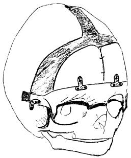
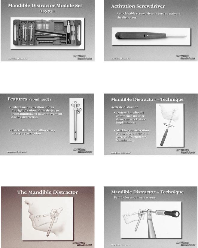
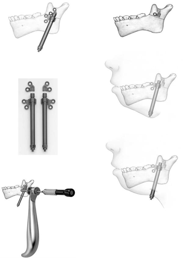
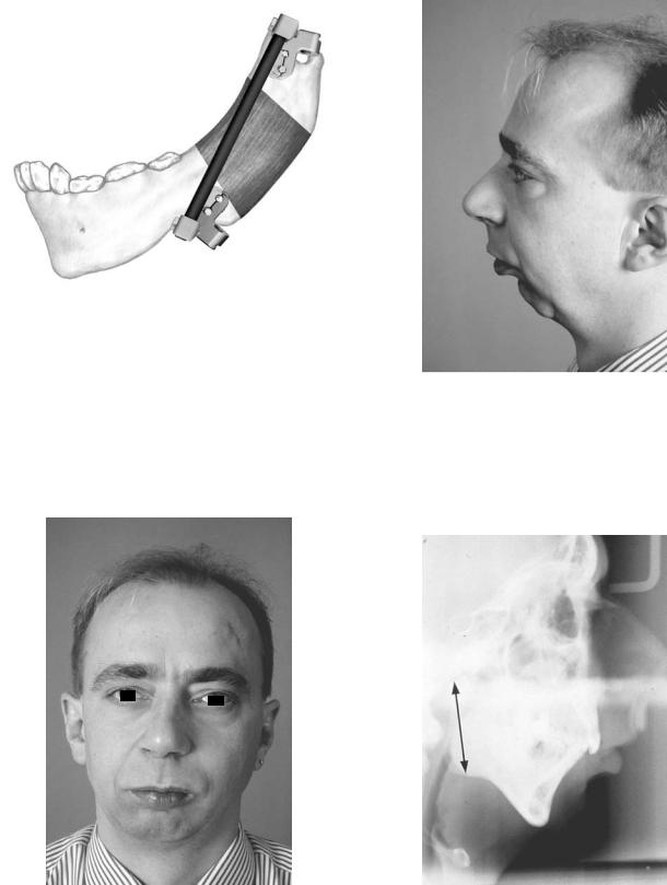
The Mandible Distractor Module Set (Figure A1.1) is composed of stainless steel implants, specifically a mandibular distractor with right foot and mandibular distractor with left foot (Figure A1.2). The distractor is placed on the mandible spanning the osteotomy site with an external activator extending through a small submandibular percutaneous incision (Figure A1.3). The screws utilized are 2.0-mm stainless steel self-tapping screws in 10-, 12-, and 14-mm lengths, and 2.4- mm stainless steel emergency screws in 10-, 12-, and 14-mm lengths. The implants are activated by an activation screwdriver. Figure A1.4 with an internal hex (Figure A1.5). This screwdriver has a directional arrow for counterclockwise activation, in which one rotation equals .5 mm. Usually, two rotations, equal to 1 mm of distraction, are recommended on a daily basis, but this is subject to variability at the surgeon’s discretion. The total days of distraction multiplied by two equals the number of days recommended for the distractor to be in place for bone consolidation to occur. The placement of the distractor requires the use of the trocar system (Figure A1.6). The module also contains the black narrow screwdriver handle, cruciform screwdriver blade (self-retaining), and 2.0- mm holding forcep (for screws).
The Titanium Single Vector Distractor
Color: Black
Indications: Mandibular ramus lengthening
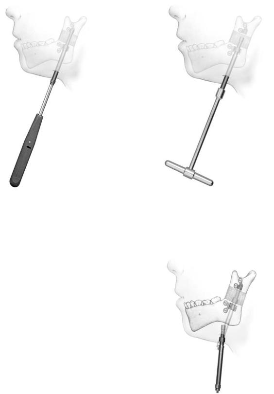
The Titanium Single Vector Distractor Module is composed of titanium implants, specifically 20-mm and 30-mm length mandibular distracts with right foot and left foot types as dis-
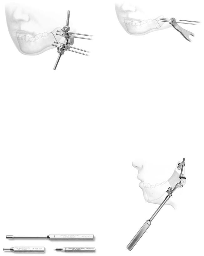
tal attachments (Figure A1.7). In addition, detached right foot and left foot proximal implants for initial bone anchorage and subsequent are mandibular distractor attachment included (Figure A1.8). The distractor is placed on the mandible spanning the osteotomy site, with an external activator extending through a small submandibular percutaneous incision. The screws utilized are 2.0 self-tapping screws in 6-, 8-, 10-mm lengths (12 and 14 are also available) and 2.4-mm emergency screws in 6-, 8-, 10-mm lengths (12 and 14 are also available). In evaluating ramus height on radiographs, the Single Vector Angulation Planner should be used to determine distractor length as well as vector and foot placement. The drilling of holes and insertion of screws is performed utilizing the plate holding trocar, which stabilizes the implant (Figure A1.9). First, on the superior aspect of the planned osteotomy, the detachable proximal foot is placed with slot inferior (Figure A1.10a). Then, the distractor body is inserted into the proximal foot (Figure A1.10b) to complete screw fixation of the distractor device. Activation and percutaneous exposure are achieved (Figure A1.10c). The implants are activated by an activation screwdriver with an internal hex (Figure A1.11), which has a directional arrow for counterclockwise activation in which one rotation equals .5 mm. Usually two rotations, which equal 1 mm of distraction, are recommended on a daily basis, but this is subject to variability at the surgeon’s discretion. The total days of distraction multiplied by two equals the number of days recommended for the distractor to remain in place for bone consolidation to occur. Following consolidation, a 3-step procedure is followed for distractor body removal. First, the activator screwdriver is turned clockwise 10 rotations (opposite to the arrow handle marker). Then distal foot disengagement is achieved by turning the distractor removal instrument 4 clockwise rotations (in the direction of the arrow marker) (Figure A1.12). Then the distractor body is removed via the percutaneous port (Figure A1.13). The module contains the black narrow screwdriver blade (self-retaining), 1.5-mm drill bits (Stryker J latch), distractor removal instrument, and activation screwdriver.
757
758
FIGURE A1.1 Mandible distractor module set. (Courtesy of Synthes Maxillofacial, Paoli, PA)
FIGURE A1.2 Mandible distractor with left foot. (Courtesy of Synthes Maxillofacial, Paoli, PA)
A.M. Greenberg and J. Prein
FIGURE A1.4 Mandible distractor activation screwdriver. (Courtesy of Synthes Maxillofacial, Paoli, PA)
FIGURE A1.5 Mandible distractor activation. (Courtesy of Synthes Maxillofacial, Paoli, PA)
FIGURE A1.3 Mandible distractor in place. (Courtesy of Synthes Maxillofacial, Paoli, PA)
FIGURE A1.6 Mandible distractor placement with transcutaneous trocar system. (Courtesy of Synthes Maxillofacial, Paoli, PA)
Appendix A1. Distraction Osteogenesis of the Mandible |
759 |
a
FIGURE A1.7 Titanium single vector distractor. (Courtesy of Synthes
Maxillofacial, Paoli, PA)
b
FIGURE A1.8 Right and left titanium single vector distractors with detachable feet. (Courtesy of Synthes Maxillofacial, Paoli, PA)
c
FIGURE A1.10 (a) The detachable proximal foot is initially placed with slot inferior, (b) the distractor is inserted for attachment, and
(c) the percutaneous incision is made exposing the activation screw. (Courtesy of Synthes Maxillofacial, Paoli, PA)
FIGURE A1.9 Insertion of screws utilizing the plate holding trocar. (Courtesy of Synthes Maxillofacial, Paoli, PA)
760
FIGURE A1.11 The distractor is activated via an activation screwdriver counterclockwise. (Courtesy of Synthes Maxillofacial, Paoli, PA)
A.M. Greenberg and J. Prein
FIGURE A1.12 Disengagement of the distractor by rotating the distractor removal instrument clockwise. (Courtesy of Synthes Maxillofacial, Paoli, PA)
The Titanium Multivector
Distractor (TMVD)
Color: Black
Indications: Mandibular bone lengthening for simple to severe hypoplasia, including straight to multidirectional requirements.
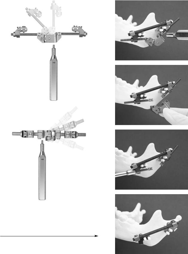
This is used as an external fixator device with percutaneous Kirschner wire (pin) implants for stabilization. The Titanium Multi-Vector Distractor (Figure A1.14) module is composed of a titanium multi-vector distractor assembly with titanium multi-vector arms in 5 lengths (15, 25, 35, 45, and 55 mm with 65, 75, and 85 mm also available) and activation instrumentation (Figure A1.15). Implants consist of 2-mm Kirschner W with thread and trocar point (pin) for self-drilling and self-tapping. Following the use of a preoperative radiograph TMVD angulation planner, an osteotomy site is performed via an intraoral or percutaneous approach. Insertion of the first pair of pins is achieved using the wire guide/ tissue protector, along with an optional trocar, thumbscrew, and check retractor ring (Figure A1.16). Then, the two infe-
FIGURE A1.13 Removal of the distractor percutaneously, leaving the foot implants in place. (Courtesy of Synthesis Maxillofacial, Paoli, PA)
Appendix A1. Distraction Osteogenesis of the Mandible |
761 |
FIGURE A1.14 Titanium multivector distractor. (Courtesy of Synthes Maxillofacial, Paoli, PA)
rior pins are inserted and the distractor assembly is placed, followed by completion of the osteotomy. Pins are cut to the desired length and adjustment of the distractor assembly is performed. Mandibular lengthening is achieved by turning the activation instrument two rotations counterclockwise; following the arrow marker is recommended (Figure A1.17), but is subject to the surgeon’s discretion. After a bony regenerate of at least 10 mm has been achieved, angular adjustment is performed using the angular adjustment instrument (Figures A1.18A and B). After consolidation has occurred, the 4.0-mm carbon fiber rod (60 and 80 mm, also available in 100-200 mm in 20-mm increments) are applied with the TMVD clamp for carbon fiber rods after the distractor assembly has been removed (Figures A1.19 and A1.20).
Distraction Osteogenesis of
the Mandible Case Report
Single vector distraction osteogenesis of the mandible is indicated for deformities of mandibular ramus hypoplasia with
FIGURE A1.16 Insertion of screws via trocar. (Courtesy of Synthes Maxillofacial, Paoli, PA)
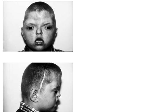
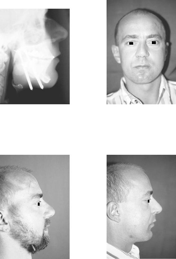
normal mandibular body horizontal size. This case report illustrates this procedure in a male with mandibular retrognathia secondary to a shortened ramus for which the patient underwent bilateral mandibular single vector distraction osteogenesis using the AO/ASIF Single Vector Distractor with improvement in occlusion from Class II to Class I and more satisfactory facial appearance (Figures A21–27). (Case report of Prof. Dr. med Joachim Prein, Kantonsspital Basel, Basel, Switzerland).
|
FIGURE A1.17 Activation of titanium multivector distractor with |
FIGURE A1.15 Titanium multivector distractor activation instrumen- |
counterclockwise turns. (Courtesy of Synthes Maxillofacial, Paoli, |
tation. (Courtesy of Synthes Maxillofacial, Paoli, PA) |
PA) |
762 |
A.M. Greenberg and J. Prein |
a
a
b
c
b
FIGURE A1.18 (a) Angular adjustment using the angular adjustment instrument. (b) Transverse adjustment using the angular adjustment instrument. (Courtesy of Synthes Maxillofacial, Paoli, PA)
FIGURE A1.19 (a) First, the carbon rod is placed. (b) The multivec- |
|
tor distractor body is removed. (c) The multivector distractor arms |
|
are then removed. (d) The carbon rod remains in place for consoli- |
d |
dation. (Courtesy of Synthes Maxillofacial, Paoli, PA) |
Appendix A1. Distraction Osteogenesis of the Mandible |
763 |
|
|
|
|
|
|
|
FIGURE A1.20 Carbon rod in place maintaining the segment positions while the bony regenerate undergoes consolidation. (Courtesy of Synthes Maxillofacial, Paoli, PA)
FIGURE A1.22 Patient with mandibular retrognathia lateral profile view.
FIGURE A1.21 Patient with mandibular retrognathia facial view.
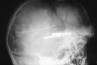
FIGURE A1.23 Preoperative lateral cephalometric radiograph demonstrating Class II malocclusion with mandibular ramus hypoplasia.
764
FIGURE A1.24 Postoperative lateral cephalometric radiograph demonstrating mandibular ramus lengthening with single vector distraction device with occlusion corrected to Class I.
A.M. Greenberg and J. Prein
FIGURE A1.26 Postoperative facial view with improved mandibular lengthening.
FIGURE A1.25 Postoperative lateral profile view with distractors still in place with percutaneous exposure.
FIGURE A1.27 Postoperative lateral profile view with improved mandibular lengthening and chin position.
Appendix A2
ITI Strauman Dental Implant System
Alex M. Greenberg
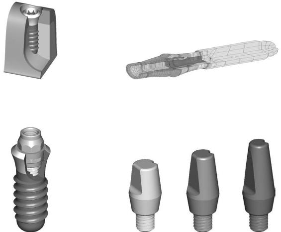
Recent developments in the ITI Strauman dental implant system (Figure A2.1) (Institut Strauman AG, Waldenburg, Switzerland) have improved the surface layer (SLE) as well as the basic prosthetic procedures (Figures A2.2 and A2.3). Illustrated here are several examples of these techniques. A
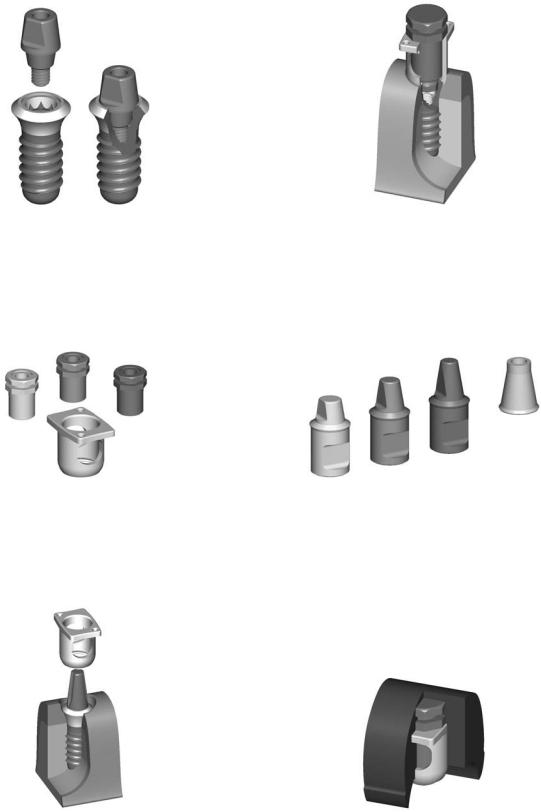
simplified technique using solid abutments (Figures A2.4 and A2.5), transfer systems for impressions (Figures A2.6–A2.8), laboratory steps (Figures A2.9–A2.12) is shown. A special orthodontic appliance is also available (Figure A2.13).
FIGURE A2.1 ITI implant in situ with ideal bone contact and gingival contour. (Courtesy of Institut Strauman AG, Waldenburg, Switzerland)
FIGURE A2.3 Finite element model of entire synOcta implant test setup. (Courtesy of Institut Strauman AG, Waldenburg, Switzerland)
FIGURE A2.2 Corresponding abutment to the synOcta implant. (Courtesy of Institut Strauman AG, Waldenburg, Switzerland)
FIGURE A2.4 Overview of solid abutments. (Courtesy of Institut Strauman AG, Waldenburg, Switzerland)
765
766
FIGURE A2.5 Wide neck ITI implant with corresponding abutment for cemented restoration. (Courtesy of Institut Strauman AG, Waldenburg, Switzerland)
FIGURE A2.6 Corresponding solid abutments with transfer system. (Courtesy of Institut Strauman AG, Waldenburg, Switzerland)
A.M. Greenberg
FIGURE A2.8 Transfer system in place for clinical application. (Courtesy of Institut Strauman AG, Waldenburg, Switzerland)
FIGURE A2.9 Implant laboratory analogs. (Courtesy of Institut Strauman AG, Waldenburg, Switzerland)
FIGURE A2.7 Transfer system for solid abutment. (Courtesy of Institut Strauman AG, Waldenburg, Switzerland)
FIGURE A2.10 Positioning cylinder and transfer coping embedded in impression material. (Courtesy of Institut Strauman AG, Waldenburg, Switzerland)
Appendix A2. ITI Strauman Dental Implant System
FIGURE A2.11 Full metal implant laboratory analog in situ. (Courtesy of Institut Strauman AG, Waldenburg, Switzerland)
767
FIGURE A2.12 Master cast with implant laboratory analog. (Courtesy of Institut Strauman AG, Waldenburg, Switzerland)
FIGURE A2.13 Indication for use with an orthodontic appliance in combination with ITI implants. (Courtesy of Institut Strauman AG, Waldenburg, Switzerland)
This page intentionally left blank