Добавил:
Опубликованный материал нарушает ваши авторские права? Сообщите нам.
Вуз: Предмет: Файл:
Учебники / Craniomaxillofacial.Reconstructive.and.Corrective.Bone.Surgery.3HAXAP.pdf
Скачиваний:
651
Добавлен:
07.06.2016
Размер:
46.49 Mб
Скачать

44

Nasal Reconstruction Using Bone Grafts and Rigid Internal Fixation

Patrick K. Sullivan, Mika Varma, and Arlene A. Rozzelle

Traditionally, reconstruction of the nasal supporting structure has been achieved with septal or auricular cartilage grafts or a combination of the two. Bone graft nasal reconstruction is advantageous, however, when significant structural support is needed or when cartilage donor sites are inadequate. The technique of bone graft nasal reconstruction has evolved over time.1–7

It has often been thought that adequate stabilization of the graft is achieved with complementary shaping of the recipient site, the inner surface of the graft, or both, aided by the compressive forces of the overlying nasal soft tissue.2,8 The underlying bone may merely be “freshened,” it may be smoothed,2,4,6,8 or it may actually be flattened by resecting the curved surface with an osteotome and applying the flat inner surface of the graft to it.2,9–11 Complementary grooves and ridges in the graft and recipient site have also been used.3 The inner surface of the graft may also be somewhat hollowed to fit the convexity of the nasal dorsum.4,9

However, wire stabilization3,4 and screw fixation5,7,10,12,13 have also been advocated. In the long term, two factors regarding bone graft survival may be applicable in the nose. First, increased bony surface area contact between the graft and the recipient bed improves bone volume conservation.14 Second, rigid fixation of bone grafts has been shown to decrease resorption and thus theoretically improve long-term maintenance of the results.15 In addition, rigid fixation of the bone graft in a cantilever fashion allows distant and sometimes multidirectional support.1,7,16

Nasal Bone Thickness

To facilitate rigid fixation of nasal bone grafts, we studied the thickness of the nasal bone in cadavers.7 The nasal bone was thickest superiorly at the nasofrontal angle (an average of 6 mm thick in the midline) and became progressively thinner toward the tip. It was 3 to 4 mm thick in the critical area where screws would be placed for fixation (in the area 5 to 10 mm inferior to the nasofrontal angle). The male nasal bones

were significantly thicker than the female nasal bones from the nasofrontal angle to the point 12 mm inferior to the nasofrontal angle (Figure 44.1).

Donor Sites

The commonly used bone donor sites are the cranium, iliac crest, and ribs. Each has advantages and disadvantages.16 Cranial bone has advantages when only bony support is needed. The donor site is preferred because it is the least conspicuous and least painful, and it is close to the operative site. Membranous bone demonstrates less resorption than endochondral bone when grafted in the face.17,18 Rigid fixation of a cranial bone graft with screws or plates is more easily accomplished due to the characteristics of the cranial bone, which includes ease of drilling and countersinking for lag screws due to the higher proportion of denser, noncompressible cortical to cancellous bone. Similarly, shaping of the graft is easier. However, when a great deal of bone is needed, it may be advantageous to harvest iliac crest bone or multiple ribs or multiple cranial grafts to form stacked-rib or stacked-cranial grafts. A single rib may be harvested if a relatively small amount of bone is required or if a bone graft with a cartilaginous extension is desired for tip support.

Fixation

Fixation has a number of advantages:1,5–7,12,13

1.Along with internal shaping, it controls the position of the graft, assuring that the correct alignment will be retained postoperatively. Without fixation, the exact position of the bone graft cannot always be predicted (Figure 44.2b).

2.Fixation of the cephalic end of the graft provides a true cantilever effect, which can improve tip projection and control.1,7,12 The thicker soft tissue at the tip of the nose exerts more compressive force on the graft than the thin tis-

483

484

FIGURE 44.1 Nasal bone thickness. The nasal bone is thickest superiorly at the nasofrontal angle (approximately 6 mm) and gradually thins inferiorly. In the critical area where a screw would be placed for fixation (approximately 5 to 10 mm from the nasofrontal angle)

sue at the cephalic end of the nose (Figure 44.2a), especially if the domes of the alar cartilages are sutured over the tip of the graft. Without fixation, the cephalic end of the graft may be displaced anteriorly, creating a high, obtuse nasofrontal angle (Figure 44.2b).

3.A rib graft can provide lateral and tip soft tissue support by carving an extension on its cartilaginous end. Fixation is necessary to maintain the orientation of such a graft.7

4.Tiered rib or cranial grafts can be constructed by securing the grafts to each other with a screw and to the recipient site with screws, thus obviating the need for an iliac crest graft (with its troublesome donor site discomfort) when a large amount of bone is needed.

5.Finally, screw fixation has been shown to decrease graft resorption,15 and thus, theoretically, it would help maintain the reconstruction in the long term.

Screw fixation has several possible disadvantages, including cost, palpability, the necessity of a stab incision at the fixation site, and possible artifact production on computed tomographic (CT) and magnetic resonance imaging (MRI) scans. The manufacturer’s charge for one screw is approximately $35. Palpability can be avoided by using microscrews or carefully countersinking miniscrews. The stab incision has proved to be barely perceptible (Figure 44.3). Artifact production on

P.K. Sullivan, M. Varma, and A.A. Rozzelle

it is approximately 3 to 4 mm thick. The nasal bone is significantly thicker in males than in females from the nasofrontal angle to approximately 12 mm inferior.

CT and MRI scans should not be clinically significant if titanium hardware is used.19

Technique

We usually place the bone graft via an open rhinoplasty approach, although a closed approach has often been used successfully. A small stab incision, vertically oriented, is made inferior to the nasofrontal angle to allow for screw placement.

We use the lag-screw technique for graft fixation (Figure 44.4). This obliterates the space that may be maintained between the graft and recipient bone by a positional screw. When using a miniscrew, it is necessary to countersink the screw head. Recently, we have been using extra long microscrews that do not require countersinking, as the head will sit flush with the bone graft surface. In the critical area where the screw(s) will be placed for fixation (5 to 10 mm inferior to the nasofrontal angle) the nasal bone is 3 to 4 mm thick (Figure 44.1). Knowing the thickness of the nasal bone here and the thickness of the carved bone graft allows calculation of the correct length of the screw to be used. Optimally, the screw should capture the inner surface of the recipient bone, but not protrude into the nasal cavity.

44. Nasal Reconstruction Using Bone Grafts and Rigid Internal Fixation

485

a

b

FIGURE 44.2 The nasal soft tissue at the tip is thicker than the cephalic soft tissue. This results in greater soft tissue compressive forces on the inferior end of the graft than on the cephalic end resulting in the situation seen in Figure 44.3a. (b) Lateral radiograph of a nasal bone

graft without fixation. The superior end of the graft is not held down by the overlying soft tissue. This may result in a high, obtuse, nasofrontal angle and loss of bone-to-bone contact.

486

P.K. Sullivan, M. Varma, and A.A. Rozzelle

a


b


c


d


FIGURE 44.3 This patient presented, after multiple nasal injuries, with a lack of support in the middle and lower thirds (tip) of the nose. [Preoperative views on left (a,c,e,g).] A cranial bone graft was shaped and placed as a cantilever via an open rhinoplasty approach

with the lag-screw technique. The domes of the alar cartilages were sutured over the inferior tip of the bone graft. Postoperative views are on the right (b,d,f,h). These show an improved nasofrontal angle, a straight, smooth dorsum, and improved tip projection.

44. Nasal Reconstruction Using Bone Grafts and Rigid Internal Fixation

487

e


f


g


h


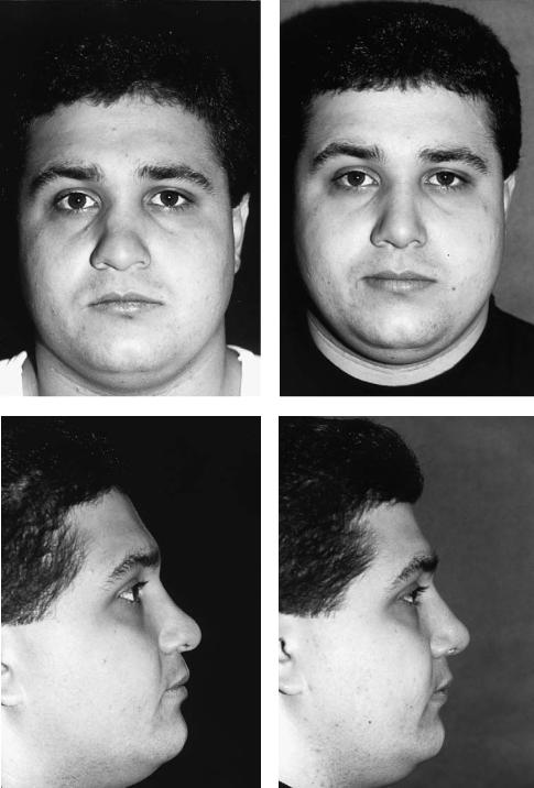
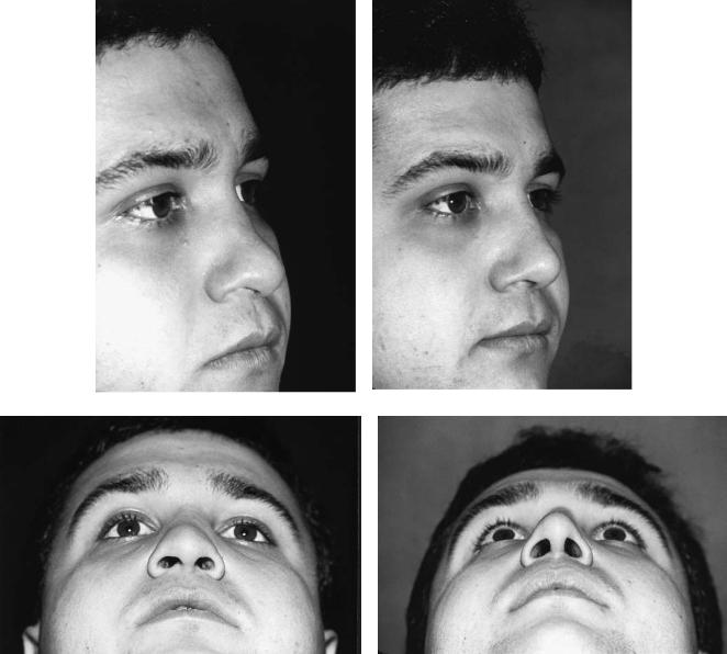
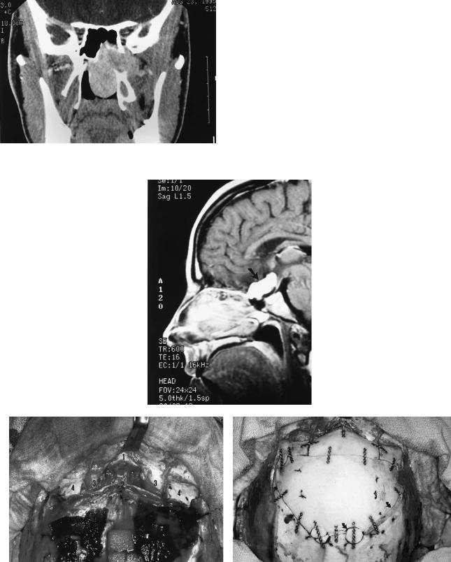
FIGURE 44.3 Continued.

488

FIGURE 44.4 Lag-screw technique. The screw passes through a channel in the graft larger than the screw diameter, without the threads capturing in the graft, thus compressing it to the recipient bone as the screw threads capture in the recipient bone. The screw head is countersunk, if a miniscrew is used, so that it will not be palpable. Currently, we use microscrews that do not require countersinking.

Summary

Fixation using extra long microscrews and the lag technique is recommended to decrease resorption and to provide graft control with enhanced soft tissue structural support. The length of the screw can be calculated by adding the thickness of the graft to the thickness of the recipient nasal bone, which is 3 to 4 mm thick in the area (5 to 10 mm inferior to the nasofrontal angle) where the fixation screw is usually placed.

References

1.Millard DR. Total reconstructive rhinoplasty and a missing link.

Plast Reconstr Surg. 1966;37:167.

P.K. Sullivan, M. Varma, and A.A. Rozzelle

2.Tessier P. Aesthetic aspects of bone grafting to the face. Clin Plast Surg. 1981;8:279.

3.Wheeler ES, Kawamoto HK, Zarem HA. Bone grafts for nasal reconstruction. Plast Reconstr Surg. 1982;69:9.

4.Stuzin JM, Kawamoto HK. Saddle nasal deformity. Clin Plast Surg. 1988;15:83.

5.Hallock GG. Cranial nasal bone grafts. Aesth Plast Surg. 1989;13:285.

6.Posnick JC, Seagle MB, Armstrong D. Nasal reconstruction with full-thickness cranial bone grafts and rigid internal fixation through a coronal incision. Plast Reconstr Surg. 1990;86:894.

7.Sullivan PK, Varma M, Rozzelle AA. Optimizing bone graft nasal reconstruction: a study of nasal bone shape and thickness.

Plast Reconstr Surg. (in press).

8.Ortiz-Monasterio F, Ruas EJ. Cleft lip rhinoplasty: the role of bone and cartilage grafts. Clin Plast Surg. 1989;16:177.

9.McCarthy JG, Wood-Smith D. In: McCarthy JG, ed. Plastic Surgery. Philadelphia: WB Saunders: Rhinoplasty. 3:1886–1890.

10.Mayot D, Perrin C, Haas F, Brunet A. Apport du gresson osseux de voute cranienne dans les septorhinoplasties d’addition.

Ann Oto-Laryngol. 1990;107:571.

11.Sheen JH, Sheen AP. Aesthetic Rhinoplasty. St. Louis: CV Mosby; 1987.

12.David DJ, Moore MH. Cantilever nasal bone grafting with miniscrew fixation. Plast Reconstr Surg. 1989;83:728.

13.Mariano A, Champy M. Fixation par vis miniaturisee des greffons osseax d’arete nasale. Ann Chir Plast Esthetique. 1986;31:381.

14.Whitaker LA. Biological boundaries: a concept in facial skeletal restructuring. Clin Plast Surg. 1989;16:1.

15.Phillips JH, Rahn B. Fixation effects on membranous and endochondral onlay bone-graft resorption. Plast Reconstr Surg. 1988;82:872.

16.Motoki DS, Mulliken JB. The healing of bone and cartilage.

Clin Plast Surg. 1990;17:527.

17.Zins JE, Whitaker LA. Membranous versus endochondral bone: implications for craniofacial reconstruction. Plast Reconstr Surg. 1983;72:778.

18.Kusiak JF, Zins JE, Whitaker LA. The early revascularization of membranous bone. Plast Reconstr Surg. 1985;76:510.

19.Sullivan PK, Smith J, Rozzelle AA. Cranio-orbital reconstruction: safety and image quality of metallic implants on CT and MR imaging. Plast Reconstr Surg. 1994;94:589.

45

Transfacial Access Osteotomies

to the Central and Anterolateral Skull Base

Robert B. Stanley, Jr.

Objectives

The transfacial access osteotomies that are discussed in this chapter are not intended for use in treatment of malignant sinus neoplasms that have invaded the skull base. Such tumors require radical resections that frequently produce unavoidable disfigurement and dysfunction. Instead, these osteotomies are designed to maintain form and function of the facial skeleton and overlying soft tissues. They provide wider and more direct access to less aggressive tumors involving relatively inaccessible areas of the skull base itself or beyond to intracranial pathology while reducing or eliminating the need for traction on the brain, brainstem, or cranial nerves. These approaches must be thought of in terms of a surgical funnel, the mouth of which is located at the level of the superficial projections of the facial skeleton and the spout at the skull base. Although the spout size will be increased only slightly or not at all, the mouth of the standard transoral, transnasal, transfrontal, and transtemporal approaches to the skull base will be greatly widened. Thus the working distance from the surgeon’s hands to the skull base or intracranial target will be shortened, but the field view angle will be maintained or increased (Figure 45.1).

Preoperative Considerations

The applicability of a transfacial approach is determined by the nature of the pathology, and the choice of approach is determined by the location of the target. Skull-base tumors that are traditionally not treated with an en bloc resection for margin control are ideal candidates for transfacial approaches. Examples range from large juvenile nasopharyngeal angiofibromas, which can be totally resected for cure, to large sphenoid wing meningiomas, which can be subtotally resected for restoration of appearance and maintenance of vision, to clivus chordomas, which can be partially resected for long-term palliation of pain and brainstem compression symptoms. Intracranial targets include suprasellar tumors as well as basi-

lar tip and midbasilar artery aneurysms. Although this broad spectrum of extracranial, junctional, and intracranial pathology occurs within a relatively small area surrounding the sphenoid bone, the complexity of this bone and the multiple structures that course through and around it necessitate the use of different approaches as determined by the exact location of the target.

The location of the target can be described in terms of its relationship to four planes that pass through the pterygoid processes of the sphenoid bone: the sagittal planes through the vertical axis of each process (Figure 45.2a), a coronal plane through the vertical axes of the processes (Figure 45.2a), and an axial plane through the level of the origin of those processes at the connection between the greater wing and body of the sphenoid bone (Figure 45.2b).

In general, targets located between the sagittal pterygoid planes and below the horizontal plane (i.e., the central skull base) can be approached through the mouth (transmandibular or transmaxillary approach). This would include targets within the region of the nasopharynx, posterior ethmoid air cells, sphenoid sinus, clivus, craniocervical junction, or upper cervical spine (Figures 45.3a and 45.4a).1–3 Additionally, pathology within the pterygoid or retromaxillary space can be reached through a maxillary osteotomy if the target lesion is centered anterior to the coronal pterygoid plane with minimal extension into the infratemporal fossa (Figure 45.5). Targets located between the sagittal planes, anterior to the coronal plane, and above the axial plane can be approached through the frontonasal area (transglabellar approach).4,5 This would include targets within the anterior cranial fossa and suprasellar area (Figure 45.6a). Any target centered lateral to a sagittal plane or posterior to the coronal plane and above the horizontal plane should be approached through the temporal fossa (transorbitozygomatic approach).6,7 This would include targets within the posterior orbit, infratemporal fossa, middle cranial fossa, parasellar area, and interpeduncular fossa (Figure 45.7a). Occasionally, a target may overlap planes and the simultaneous use of two approaches may be required. Also, although technically difficult, it is possible to remove the me-

489

490

FIGURE 45.1 Surgical funnel. For a given surgical field width (i.e., the space for the surgeon’s hands, instruments, and line of sight for binocular vision), the working distance must be increased for a stan-

R.B. Stanley, Jr.

dard approach compared to an approach via an osteotomy. The potential intracranial field of view is also reduced for the standard approach if the surgical field width is to be maintained.

a

b

FIGURE 45.2 Pterygoid planes. (a) Sagittal planes (small arrows) and coronal plane (large arrow). Numbered structures are (1) clivus; (2) foramen lacerum; (3) occipital condyle; and (4) carotid canal. (b)

Axial plane (arrow). Numbered structures are (1) clivus; (2) sphenoid sinus; (3) medial pterygoid lamina; (4) hard palate; and (5) frontal sinus.

45. Transfacial Access Osteotomies to the Central and Anterolateral Skull Base

491

a

b

c

FIGURE 45.3 (a) Preoperative coronal MRI shows basilar invagination of cervical spine into foramen magnum (arrow) in patient with metabolic bone disease. Numbered structures are (1) atlas; (2) axis; and (3) third cervical vertebral body. (b) Intraoperative view of the same patient at level of craniocervical junction (arrow), as seen through midline labiomandibular glossotomy. Numbered structures

dial and lateral laminae of a pterygoid process and reach a lateral target from a transoral approach or a central target from a lateral approach.

are (1) bivalved tongue; and (2) retracted soft palate. (c) Postoperative radiograph following removal of odontoid. Because of poor bone quality, a THORP plate (Synthes) (large arrow) with hollow screws and 2.0-mm tension band plate (small arrow) were used to stabilize mandibulotomy. Large vertical plates are part of posterior spinal fusion. (Courtesy of Synthes Maxillofacial Paoli, PA)

non–tooth-bearing bone, such as through the orbitozygomatic complex and frontal bone, can produce free segments that can be removed from the surgical field and reinserted.

Osteotomies

Osteotomies that mobilize tooth-bearing bone or any segment of bone covered by oral mucosa must, of course, maintain the bone as an osteoplastic segment. Osteotomies that mobilize

Transmandibular and Transmaxillary

These transoral osteoplastic approaches allow the surgeon to work within limits established by the pterygoid processes cranially and the carotid arteries caudally. The transmandibular approach provides access to only the lowest part of the clivus,

492

R.B. Stanley, Jr.

a

b

c

d

FIGURE 45.4 (a) Preoperative arteriogram that demonstrates a midbasilar artery aneurysm (arrow). (b) Model showing 1.5-mm plates attached across Le Fort I level osteotomy prior to downfracture of maxilla. (c) Plates removed and maxilla downfractured to expose the

clivus. X marks the level of the target aneurysm in relationship to the anterior surface of the clivus. (d) Postoperative axial CT scan shows the transclival successful application of the aneurysm clip (arrow).

45. Transfacial Access Osteotomies to the Central and Anterolateral Skull Base

493

FIGURE 45.5 Coronal CT scan showing large juvenile nasopharyngeal angiofibroma extending through the pterygomaxillary fissure. Total excision was accomplished through maxillotomy approach.

a

b

c

FIGURE 45.6 (a) Sagittal MRI demonstrates a large suprasellar schwannoma (arrow). (b) Intraoperative view of osteotomy site from above after dural closure. Numbered structures are (1) nasal bones;

(2) area of foramen cecum; (3) orbital soft tissue; and (4) frontal bar

lateral to supraorbital formina. (c) Reconstruction with 1.0-mm plates and screws. All craniotome cuts and burr holes have been closed by advancing the bone flap or inserting split cranial grafts (arrows).

494

R.B. Stanley, Jr.

a

b

c

FIGURE 45.7 (a) Preoperative arteriogram demonstrating aneurysm (arrow) of the tip of the basilar artery. (b) Model with lines of four osteotomies marked. See text for details. (c) Reconstruction with 1.0- mm plates and screws. Numbered structures are (1) reinserted zy-

but it is an excellent approach to the upper cervical spine and in most cases the craniocervical junction (Figure 45.3b). A lower lip-splitting incision is required, but the visibility of the healed scar can be minimized by using a stepped or notched course through the vermilion of the lip, then following relaxed skin tension lines around the chin to the level of the hyoid bone. The osteotomy through the anterior mandible can be performed directly in the midline or in a parasagittal stepped fashion. Neither approach should require removal of a tooth if a fine-cut- ting burr, saw, or osteotome is used between the tooth roots.

The tongue can then be split in the midline or an incision can be directed around the tongue across the floor of mouth to the pharynx. The midline glossotomy requires more time for closure, but the floor-of-mouth incision places the hypoglossal and lingual nerves at risk for injury. Exposure of the craniocervical junction often requires splitting of the soft palate, and this should be done with a “lazy-S” type incision placed to the side of the uvula to reduce the amount of palatal shortening and possible velopharyngeal incompetence that will result. The posterior pharyngeal mucosa can be incised in the midline or an inferiorly based flap can be created, depending on what is to be accomplished when the spout of the surgical funnel has been reached.

Stable fixation of the mandibulotomy, which eliminates the need for postoperative maxillomandibular fixation, can be achieved through a variety of techniques. Theoretically, compression osteosynthesis should not be used to close anterior

goma; and (2) split cranial graft placed to augment floor of temporal fossa where temporalis muscle has been detached deep to lateral orbital rim. This will prevent the temporal hollowing that tends to occur even if muscle is reattached to the rim.

mandibulotomies made with a saw-cut. It must be remembered that even the finest osteotomy creates a gap between the bone segments, and a change in the occlusal relationship will occur if this gap is closed. Although the successful use of compression osteosynthesis for anterior mandibulotomies done with an osteotome has been described,8 this type of osteotomy may be more difficult to perform and be of greater risk to the teeth. To ensure that the most accurate realignment of the mandibular segments is achieved during repair of an osteotomy created by a saw-cut, noncompressing fixation plates should be adapted across the line of the proposed osteotomy, and all screw holes should be drilled in an exact neutral position in relation to the plate holes. The plates are then removed and the osteotomy completed. At the time of repair, the preadapted plates are reattached, again with all screws in a neutral position in the plate holes. The type and number of plates and screws used and their points of attachment to the anterior mandible can vary, depending on the status of the dentition, the presence of any metabolic bone disorders, and the experience and preference of the surgeon (Figure 45.3c). In the end, the occlusal patterns should be unchanged, immediate mobilization and early function should be possible, and uncomplicated bony healing should proceed at the osteotomy site.

The transmaxillary approach is a Le Fort I–level maxillotomy with downfracture that provides excellent exposure of the central skull base except at the level of the craniocervical junction.9 The osteotomy is made through the zygomatico-

45. Transfacial Access Osteotomies to the Central and Anterolateral Skull Base

495

maxillary buttresses at a level that leaves sufficient bone above the roots of the maxillary teeth for attachment of the transverse limb of an L-shaped minifixation plate (1.3 or 1.5 mm) and through the nasomaxillary buttresses into the nose below the anterior end of the inferior turbinate. Fixation plates should be adapted to the four buttresses, and all screw holes should be drilled before the osteotomy is made or after it is completed but before the maxilla is detached from the posterior pterygomaxillary buttresses (Figure 45.4b).

The nasal septum is managed in a way very similar to a transseptal approach to the sphenoid sinus for adenohypophysectomy. The mucosa is elevated from one side of the cartilaginous portion of the septum, the bony–cartilaginous junction is identified and separated, and then a bilateral submucoperiosteal dissection is completed over the bony septum to the sphenoid rostrum. The bony septum is then removed piecemeal and the cartilaginous septum is elevated off the maxillary crest, which is preserved if possible for later septal reconstruction. After the mucosa of the floor of the nose is elevated bilaterally, an incision is made through the posterior margin of the septal mucoperiosteum and carried out bilaterally through the elevated floor mucosa just anterior to its transition into soft palate. The leaves of septal mucoperichondrium/periosteum are then separated, carrying the septal cartilage to one side still attached to mucoperichondrium. Preservation of the septal cartilage reduces the chance of developing a troublesome anterior septal perforation and maintains support for the nasal dorsum and tip when the cartilage is repositioned onto the retained maxillary crest. Removing the posterior one third to one half of the inferior turbinate will widen the funnel as it approaches the spout, but removing additional turbinate tissue increases the risk of producing atrophic rhinitis symptoms.

Once the maxilla is detached from the pterygoid processes and downfractured, it remains pedicled on the contents of the pterygomaxillary fissure as well as the soft tissues of the palate and faucial pillars. Therefore, it does not move downward evenly to produce a box-like opening, but rather it hinges around the soft tissue pedicles to produce the surgical funnel (Figure 45.4c,d). If further exposure is required, a parasagittal split through the hard palate (maintaining the maxillary crest for reconstruction of the septum) and the soft palate can be performed to create a bivalved maxilla. This maneuver produces unhindered access above and below the craniocervical junction but carries a possible increased risk of aseptic necrosis of the maxillary segments due to kinking of the vascular pedicles. Retraction pressure should be released from time to time to ensure vascular perfusion of both segments in their downward, rotated position. Also, velopharyngeal incompetence may result from the midline split of the soft palate. If the palate is to be split, an additional fixation plate must be adapted across the proposed exit of the osteotomy through the inferior margin of the pyriform aperture and all screw holes drilled. A plate positioned across the posterior extent of the osteotomy should also be considered for maximum stability of the reconstruction. However, application of this plate can sometimes be techni-

cally difficult, and a high rate of exposure through the repaired mucosa often necessitates a second surgery for its removal.

Transglabellar

This free-segment approach, when done in conjunction with a frontal craniotomy, facilitates both intradural and extradural dissections by the neurosurgeon along the floor of the anterior cranial fossa. The need for traction on the brain and olfactory nerves is lessened with improved visualization of the suprasellar area. The free segment is removed from the frontal bar of the forehead after dissection of the standard coronal flap is carried over the superior orbital rims and down onto the nasal bones, stopping just short of the medial canthal tendons. The supraorbital neurovascular bundles are then freed from their foramina, and both trochlear tendons are detached from the mediosuperior corner of the orbits. Dissection is carried back along the orbital roofs and down to the frontoethmoidal suture line at the level of the anterior ethmoid artery. Intracranially, the dura is elevated down to the foramen cecum, and the venous channel through this foramen is clipped and transected. After identification of the crista galli, the dura is elevated from both orbits without violating either olfactory tract. Vertical bone cuts are then made through the frontal bar perpendicular to the transverse frontal cut of the craniotomy and into the orbital roofs at the supraorbital notches. These cuts are then connected by a transverse cut across the floor of the anterior fossa at the level of the foramen cecum. The final osteotomy is through the frontonasal suture, angled superiorly toward the foramen cecum. Small cuts with an osteotome in the mediosuperior aspect of the orbit are usually necessary to completely mobilize the central segment of the frontal bar (Figure 45.6b).

Most of the frontal sinus will be contained within the removed segment, and an appropriate form of management of the sinus is cranialization. This is performed by removing the posterior table of the sinus and totally extirpating all mucosa from the anterior wall with round cutting burs. Any sinus that extends into the frontal bone flap or that remains in situ as a lateral extension is treated in a similar fashion. Following completion of the neurosurgical procedure, the frontal segment is replaced and stabilized with microplates and screws (1.0 mm). Split inner table grafts harvested from the frontal bone flap are contoured to fit tightly into the area of the frontonasal orifices and then covered with temporalis fascia to complete the seal between the anterior fossa and the nose and paranasal sinuses. Because a pericranial flap rotated intracranially is usually unnecessary for repair of the dura or skull base in these cases, the frontal bone flap should be advanced to completely close the transverse bone cut made by craniotome (Figure 45.6c). This will prevent a linear depression from developing across the supraciliary and glabellar areas. The widened gap at the superolateral rim of the frontal bone flap, which most likely will be behind the hairline, can be filled with “bone pâté” saved from the craniotomy or strips of split inner table bone from the frontal bone flap.

496


R.B. Stanley, Jr.

Transorbitozygomatic

ative edema to further facilitate the approaches, and their

This is a combined osteoplastic-free-segment approach

short-term administration does not appear to increase the risk

of infection, even with the transoral approaches. An attempt

through the temporal fossa. It necessitates complete exposure

should be made to obtain a watertight suture closure of dural

of the lateral orbit, body of zygoma, and zygomatic arch

and mucosal incisions. However, this may not always be pos-

through an extended hemicoronal dissection. This dissection

sible at sites deep within the intracranial cavity or high in the

must be maintained at a level deep to the superficial layer of

nasopharynx. Short-term augmentation of a tenuous closure

the deep temporal fascia to avoid damage to the frontal branch

of either suture line can be obtained with fibrin adhesive, and

of the facial nerve. Two osteotomies through the arch, one

pressure from cerebrospinal fluid on the dural closure can be

placed obliquely through the articular eminence and one

reduced with lumbar drainage for a 3- to 5-day period. Ali-

placed paralleling the lateral margin of the orbital rim (Fig-

mentation should be given by way of a small-diameter, soft

ure 45.7b), allow for lateral and inferior retraction of the arch

nasogastric feeding tube also for a 3- to 5-day period in pa-

without the need for detachment of the masseter muscle. This

tients who undergo transoral approaches. An orogastric tube,

prevents the inferior retraction of the muscle and the resul-

which is somewhat more uncomfortable for the patient, or pe-

tant transcutaneous accentuation of the arch outline that oc-

ripheral intravenous alimentation can be used if there is con-

curs when the arch is removed and replaced as a free seg-

cern regarding the presence of a tube in close proximity to a

ment. The body of the zygoma is then removed as a free

nasopharyngeal repair. A tracheostomy should not be neces-

segment by first detaching the temporalis muscle from the lat-

sary except in patients who undergo a midline labio-

eral orbit and temporal fossa, and then creating two additional

mandibular glossotomy or in patients who will likely have

osteotomies (Figure 45.7b). One osteotomy extends through

airway or aspiration problems related to postoperative lower

the body of the zygoma into the lateral end of the inferior or-

cranial nerve palsies caused by the neurosurgical portion of

bital fissure, and the other extends from the lateral end of the

the case.

fissure superiorly along the zygomaticosphenoid suture line


to pass obliquely through the base of the zygomatic process

Acknowledgments. The author would like to thank H. Richard

of the frontal bone. When used in conjunction with a tempo-

Winn, M.D., Professor and Chairman, and M. Sean Grady,

ral craniotomy, increased exposure of the junction of the tem-

M.D., Associate Professor, of the Department of Neurologi-

poral fossa and infratemporal fossa, posterior orbit, middle

cal Surgery, University of Washington School of Medicine,

cranial fossa, parasellar area, and interpenduncular fossa is

Seattle, WA, for the opportunity to participate in the care of

obtained.

their patients.

Following completion of the neurosurgical procedure, the


posterior orbit is reconstructed as necessary with split cranial

References

bone grafts, and the zygoma and zygomatic arch are reposi-

tioned and stabilized (Figure 45.7c). The osteotomy gaps

1.

Archer DJ, Young S, Utley D. Basilar aneurysms: a new trans-

through the body of the zygoma and the anterior arch are


clival approach via maxillotomy. J Neurosurg. 1987;67:54–58.

closed and stabilized with 1.0- or 1.3-mm plates and screws.


2.

Grime PD, Haskell R, Robertson I, Gullan R. Transfacial access

The oblique osteotomies through the zygomatic process of the


of neurosurgical procedures. I. The upper cervical spine and

frontal bone and the articular eminence of the arch, which act


clivus. Int J Oral Maxillofac Surg. 1991;20:285–290.

as sliding osteotomies due to closure of the other gaps, can

3. Sasaki CT, Lowlicht RA, Astrachan DI, Friedman CD, Goodwin

be stabilized with plates or with lag screws. The temporalis


WJ, Morales M. LeFort I osteotomy approach to skull base.

muscle must be firmly reattached to the lateral orbital rim and


Laryngoscope. 1990;100:1073–1076.

superior temporal line if temporal hollowing is to be avoided.

4.

Raveh J, Vuillemin T. The subcranial-supraorbital and temporal

Additionally, bone grafting to the floor of the temporal fossa


approach for tumor resection. J Craniofac Surg. 1990;1:53–59.

5. Shekahr LN, Nanda A, Sen CN, Snyderman CN, Janecka IP. The

should be considered to help maintain overlying soft tissue

contours.


extended frontal approach to tumors of the anterior, middle, and


posterior skull base. J Neurosurg. 1992;76:198–206.


6. Grime PD, Haskall R, Robertson I, Gullan R. Transfacial access

Miscellaneous Considerations


for neurosurgical procedures. II. Middle cranial fossa, infratem-


poral fossa, and pterygoid space. Int J Oral Maxillofac Surg.


1991;20:291–295.

A broad-spectrum antibiotic, typically a cephalosporin, is ad-

7. Alaywan M, Sindou M. Fronto-temporal approach with orbito-

ministered to all patients preoperatively and continued for 72


zygomatic removal. Acta Reconstr Surg. 1992;87:362–364.

8. Hale RG, Timmis DP, Bays RA. A new mandibulotomy tech-

hours postoperatively. For transoral procedures that include


nique for the dentate patient. Plast Reconstr Surg. 1991;87:362–

exposure of the dura, metronidazole is added. A steroid bo-


364.

lus, usually 12 mg of dexamethasome, is also given preoper-


9.

Janes D, Crockard HA. Surgical access to the base of skull and

atively, and doses of 6 mg are continued every 6 hours for 24


upper cervical spine by extended maxillotomy. Neurosurgery.

hours postoperatively. The steroids greatly reduce intraoper-


1991;29:411–416.

Section V

Craniomaxillofacial Corrective

Bone Surgery