

22
AO/ASIF Mandibular Hardware
Joachim Prein and Alex M. Greenberg
The AO/ASIF mandibular systems of instruments and titanium implants have been developed primarily for the correction of deformities, distraction osteogenesis, reconstruction of defects, and fixation of fractures of the mandible. The mandibular system consists of stronger and larger screws and plates than those utilized in the craniofacial modular system. These are necessary because of the dynamic functional forces acting on the mandible, as compared to the static forces associated with the maxilla. Stronger implants are also required because the mandible is a heavier, thicker, and articulated bone with varied mechanical loading. The mandibular modules are organized according to screw sizes—2.0 mm, 2.4 mm, 3.0 mm, and 4.0 mm. Implant systems with screws sizes less than 2.0 mm are rarely applied in mandibular surgery. These hardware systems based on screw size are uniform worldwide, as approved by the AO/ASIF Maxillofacial Technical Commission. There are some differences in tray or module configurations depending on the distributor (Synthes Maxillofacial in North America and STRATEC and Mathys for the rest of the world). The different mandibular systems, which range in size from 2.0 mm to 4.0 mm, are arranged in color-coded trays or modules. The Synthes Maxillofacial system for North America is called the Modular Fixation System (Figures 22.1 and 22.2a,b), while the Mathys and STRATEC system from Europe is the Compact MF System (Figures 22.3 and 22.4). Not only are these modules organized by screw size, but also by type of surgery performed—trauma, reconstruction, or orthognathic. For the latest surgical technique of bone distraction, a separate Mandible Distractor Module Set has been developed (Appendix A.1).
The instrumentation for mandibular corrective surgery is contained within the module of the craniofacial modular system. Both the North American and European systems have separate trays that contain the universal instruments. The North American system has two trays, of which the top tray contains the transbuccal instruments as follows: 2.0 mm/2.4 mm Trocar with obturator; 2.0-mm and 2.4-mm obturators; cheek retractor ring; cheek retractor blade 1.5-mm, 2.0-mm, 1.8-mm, and 2.4-mm drill guides; 1.5-mm/2.0-mm insert drill guide; 1.8-mm neutral drill guide; 1.8-mm compression drill
guide; 2.4-mm depth gauge (measures up to 40 mm) in regular and extra large; wide screwdriver handle; narrow screwdriver handle; cruciform screwdriver (self-retaining) for 2.0-mm and 2.4-mm screws; cruciform screwdriver with holding sleeve for 2.0-mm and 2.4-mm screws; tap handle; counter/sink; and 1.8-mm DCU drill guide (neutral and load). The lift-out lid for the auxiliary bin of the top tray contains 1.8 and 2.4-mm pins for countersink; 2.0-mm and 2.4-mm taps; 1.8-mm 125-mm drill bit; and 2.4-mm 125-mm drill bit. The bottom universal instrument tray contains plate holding forceps; bone reduction forceps (short and long); bending pliers for 2.0-mm/2.4-mm plates locking; bending pliers for 2.0-mm/2.4-mm plates nonlocking; universal bending irons (2); bending pliers for 2.4-mm plates; 3-in-1 Bending Pliers for 2.0-mm plates (Figure 41.19); shortcut plate cutters (2); plate cutter for 2.0-mm/2.4-mm plates (double action), ratcheting screwdriver (Figure 22.27), and battery powered screwdriver (Figure 22.28). The STRATEC and Mathys systems include the same instruments, which may be placed in either one or two trays at the bottom of the graphic case (Figure 22.5a,b).
2.0 Mandible Locking Plate
System (MLP) Module
Color: Blue (Synthes Maxillofacial for North America and Compact MF for Europe and Worldwide)
Indications: Trauma, simple to unstable fractures, microvascular reconstructive surgery, and orthognathic surgery
The 2.0-mm MLP system module (Figure 22.6) contains plates and screws for the management of simple to unstable fractures. The plates are available in 3 thicknesses (1.0 mm, 1.3 mm, 1.5 mm) to accommodate a wide range of indications. The module contains 2.0-mm self-tapping and self-drilling locking and nonlocking gold-colored star drive-headed screws available in 5, 6, 8, 10, 12, 14, 16, and 18 mm. 2.4-mm teal colored emergency screws are available in the same lengths.
Number embossed markers attach to the top of each modular
269
270 |
J. Prein and A.M. Greenberg |
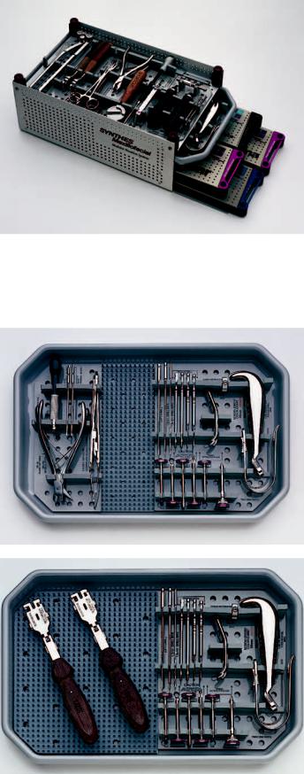
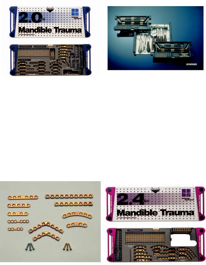
FIGURE 22.1 Mandibular Modular Fixation System Graphic Case.
(Courtesy Synthes Maxillofacial, Paoli, PA)
a
b
FIGURE 22.2 (a,b) Mandibular Modular Fixation System
Universal Instrument Trays. (Courtesy Synthes Maxillofacial,
Paoli, PA)
22. AO/ASIF Mandibular Hardware |
271 |
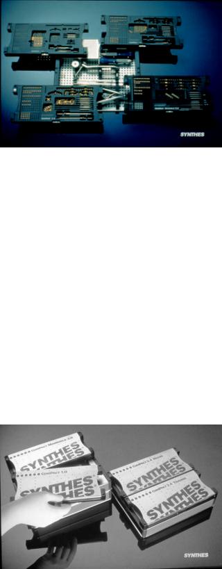
FIGURE 22.3 Compact MF System modules and instrument tray. (Courtesy of STRATEC Medical, Oberdorf, Switzerland and Mathys LTD Bettlach, Bettlach, Switzerland)
screw row indicate the screw length for the customized module in use. Self drilling screw markers have a white background and self tapping screw markers have a black background. Corresponding drill bits for plate fixation are 1.5 mm. Drill bits are available in J latch, Jacob’s chuck, Universal, and mint quick coupling. A tap is available for pretapping holes before the placement of screws in dense cortical bone. Long and short star drive screw driver (self retaining) for both the regular and ratchet type screw drivers is included. There are 1.5 mm regular and threaded drill guides. The 2.0 MLP module includes mini thickness implants as follows (Figure 22.7): malleable straight 4 and 6 holes, mini straight narrow 4 and 6 hole, adaption 20 hole, tension band 4 hole, broad straight 4 hole, and broad curved 4 hole. Intermediate thickness implants as a straight 6 hole and straight 12 hole. Large thickness implants as straight 6 hole, straight 12 hole, and straight 20 hole. Angled implants as: crescent angled 3 3
FIGURE 22.4 Compact MF System Graphic Case. (Courtesy of STRATEC Medical, Oberdorf, Switzerland and Mathys LTD Bettlach, Bettlach, Switzerland)
holes, angled 4 4 holes, angled left 6 21 holes, and angled right 6 21 holes.
2.0 Mandible Trauma
Module Color: Blue (Synthes Maxillofacial for North America and Compact MF for Europe and Worldwide)
The 2.0 Mandible Trauma module (Figures 22.8, 22.9, and 22.10) contains 2.0-mm fluted self tapping screws in 4-, 6-, 8-, 10-, 12-, 14-, 16-, and 18-mm lengths (up to 24 mm) and 2.4-mm emergency teal-colored screws in 6-, 8-, 10-, 12-, 14-, 16-, and 18-mm lengths (up to 24 mm). Number-embossed markers attach to the top of each modular screw row indicate the screw length for the customized module in use. The corresponding drill bits for plate fixation are 1.5 mm 110 mm
(3). For lag screw technique, the 2.0-mm 110-mm (3) drill bit is for the gliding hole, and the 1.5-mm drill bit is for the threaded hole. The drill bits are available in Stryker J Latch, Jacob’s Chuck, Universal, or Miniquick coupling. A tap is available for pretapping holes before the placement of extralong screws in thick cortical bone. A cruciform screwdriver blade (self-retaining) for 1.5-mm/2.0-mm screws is included. The 2.0 mandible miniplates are thicker (1.0 mm) and stronger than the 2.0-mm miniplates for the midface. The Synthes Maxillofacial System (Figure 22.8b) includes limited contact implants as follows: straight plate; narrow (4, 6, and 8 holes); straight plates, broad (4, 6, and 8 holes); curved plate (narrow) (4 and 6 holes); and curved plate (broad) (4 and 6 holes). Other implants include adaption plate (20 holes), DCP (4, 5, 6, 7, and 8 holes), DCP (angled) 4 4 holes (8 holes); mandible strut plate 4 4 holes (8 holes), LC-EDCP (4 and 6 holes).
The Compact MF 2.0 Mandible System consists of a combination 2.0 midface/mandible module and a separate 2.0 unilock/locking plate system. The STRATEC and Mathys 2.0 Mandible system (Figure 22.8a) includes miniplates with center space (2, 4, and 6 holes); miniplates (2, 4, or 20 holes); miniplates twisted 70° with center space, left, and right (6 holes); mini DCP (20 holes); and LC miniplate with center space (4 and 6 holes). These plates are mainly used for simple mandibular fractures with good bony buttresses, either as single-plate fixation or a two-plate fixation system (one plate along the tension side, and the other on the pressure side of the fracture).
2.4 mm Mandible Trauma Module
Colors: Red (Compact MF for Europe and Worldwide) Purple (Synthes Maxillofacial for North America) Indications: Simple to complex mandibular fractures including comminution and avulsive defects.
The 2.4 Mandible Trauma system consists of one module in North America and two modules in Europe and Worldwide
272 |
J. Prein and A.M. Greenberg |
a |
b |
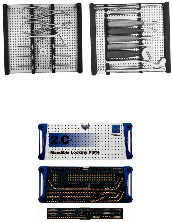
FIGURE 22.5 (a) Compact MF 2.4-mm universal instrument tray containing trocar system and bone-and-plate holding forceps. (b) Compact MF 2.4-mm universal instrument tray containing depth gauge,
drill guides, screwdriver handles, plate cutters, and plate bender. (Courtesy of STRATEC Medical, Oberdorf, Switzerland and Mathys LTD Bettlach, Bettlach, Switzerland)
FIGURE 22.6 A 2.0 Mandible Locking Plate Module Set. (Courtesy of Synthes Maxillofacial, Paoli, PA)
22. AO/ASIF Mandibular Hardware
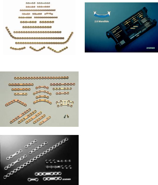
FIGURE 22.7 2.0 Mandible Locking Plate System selection of implants. (Courtesy of Synthes Maxillofacial, Paoli, PA)
a
b
FIGURE 22.8 (a) 2.0-mm Mandible Trauma Module selection of implants for North America. (Courtesy of Synthes Maxillofacial, Paoli, PA) (b) Compact MF 2.0 Mandible Trauma Module selection of implants for Europe and worldwide. (Courtesy of STRATEC Medical, Oberdorf, Switzerland and Mathys LTD Bettlach, Bettlach, Switzerland)
273
FIGURE 22.9 Compact MF 2.0 Mandible Trauma Module with liftout tray for 2.0 Midface Plates. (Courtesy of STRATEC Medical, Oberdorf, Switzerland and Mathys LTD Bettlach, Bettlach, Switzerland)
(2.4-mm Trauma and 2.4-mm UniLock/Locking Reconstruction Plate systems) (Figures 22.11, 22.12, and 22.13). The 2.4-mm trauma module contains plates and screws for the management of more extensive, complex, fragmented, and avulsive fractures, as compared to the 2.0-mm trauma module. The plates are thicker for example, 1.65 mm for the straight LCDCP and 2.0 mm for the crescent LC-DCP. The module contains 2.4-mm gold-colored self-tapping screws 6-, 8-, 10-, 12-, 14-, 16-, and 18-mm screws (20, 22, 24, 26, 28, and 30 are also available). The Synthes Maxillofacial Module includes an additional pop-up tray that contains 2.4-mm gold-colored selftapping 32-, 34-, 36-, 38-, and 40-mm screws. Emergency 2.7- mm teal-colored screws in 6-, 8-, 10-, 12-, 14-, 16-, and 18mm lengths (available up to 30 mm). Number-embossed markers attach to the top of each modular screw row indicate the screw length for the customized module in use. The corresponding drill bits for plate fixation are 1.8 mm 100 mm (3 each). For lag-screw technique, the 2.4 mm 100 mm (3 each) is used for the gliding hole and the 1.8 mm 100 mm drill bit for the threaded hole. The drill bits are available as J- Latch, Jacob’s chuck, or mini/quick coupling. Although the screws are self-tapping, a tap is included for those instances where pretapping is necessary, such as long lag screws in solid cortical bone of the symphysis. The implants include the limited contact LC-DCP (straight 4, 5, and 6 holes); LC-DCP crescent (4 and 6 holes); 2.4-mm tension band plates (4 and 6 holes); universal fracture plate (straight) (8, 10, and 24 holes), and angled 3 3 (6 holes) and 4 4 (8 holes) (Figure 22.11). The 3 3- and 4 4-angled universal fracture plates are indicated for mandibular angle fractures, and they are similar to reconstruction plates in that they are three dimensionally bendable. However, as the universal fracture plate thickness is 2.0 mm, compared to 2.5 mm for reconstruction plates, they are weaker and should not be used in higher load-bearing situations (i.e., avulsive defects).
274
FIGURE 22.10 2.0-mm Mandible Trauma Module for North America. (Courtesy of Synthes Maxillofacial Maxillofacial, Paoli, PA)
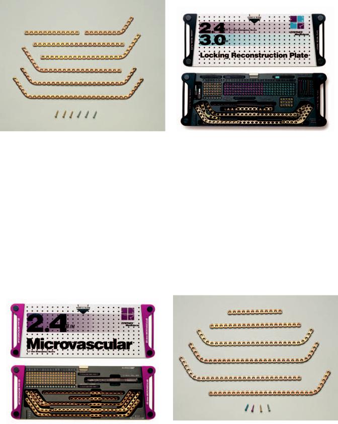
2.4-mm Microvascular Module
Color: Purple (Synthes Maxillofacial/North America availability only).
Indications: Mandibular continuity defect reconstruction with microvascular anastamosed bone grafts.
The 2.4-mm Microvascular Module (Figures 22.14 and 22.15) contains 2.4-mm self-tapping screws in 6-, 8-, 10-, 12-, 14-, 16-, and 18-mm lengths (available up to 40 mm), and emergency screws in 6-, 8-, 10-, 12-, 14-, 16-, and 18-mm lengths
FIGURE 22.11 2.4-mm Mandible Trauma Module selection of implants. (Courtesy of Synthes Maxillofacial, Paoli, PA)
J. Prein and A.M. Greenberg
FIGURE 22.12 Compact MF 2.4-mm Mandible Trauma and 2.4 UniLock Reconstruction modules. (Courtesy of STRATEC Medical, Oberdorf, Switzerland and Mathys LTD Bettlach, Bettlach, Switzerland)
(available up to 40 mm). The corresponding drill bits are 1.8
mm100 mm (3 each) for plate fixation and 2.4 mm 100 mm for lag-screw technique. The implants come as microvascular plates (straight) (12, 14, 16, 18, 20, 22, and 24 holes), microvascular plate (angled) 4 8 (12 holes), right and left, 4 16 (20 holes), right and left, 5 17 (22 holes), right and left, microvascular plate, double angle 4 20 4 (28 holes), 5 22 5 (32 holes), and 6 24 6 (36 holes) (Figure 22.14). Corresponding templates are also available for these plates. These plates are similar to the universal fracture plates.
FIGURE 22.13 2.4 mm Mandible Trauma Module for North America. (Courtesy Synthes Maxillofacial, Paoli, PA)
22. AO/ASIF Mandibular Hardware
FIGURE 22.14 2.4-mm Microvascular Module selection of implants. (Courtesy of Synthes Maxillofacial, Paoli, PA)
2.4/3.0 mm Locking Reconstruction Plate System Module
Colors: Purple (Compact MF for Europe and Worldwide) Black (Synthes Maxillofacial for North America) Indications: Mandibular continuity defect reconstruction with and without bone grafts, and complex mandibular fractures including comminution and avulsive defects.
The 2.4 mm/3.0 mm Locking Reconstruction Plate System module contains reconstruction plates with threaded plate holes and corresponding threaded head screws is indicated for posttraumatic and postablative defects (Figures 22.16 and 22.17).
FIGURE 22.15 2.4-mm Microvascular Module. (Courtesy of Synthes Maxillofacial, Paoli, PA)
275
FIGURE 22.16 A 2.4 mm/3.0 mm Locking Reconstruction Plate Module. (Courtesy of Synthes Maxillofacial, Paoli, PA)
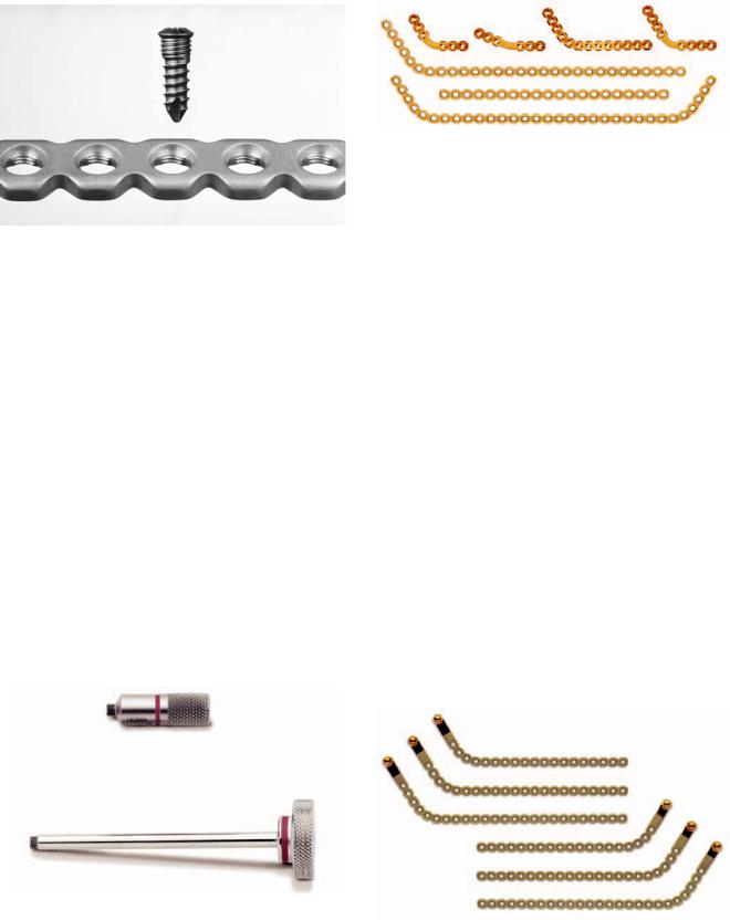
The plate is the same thickness as the standard reconstruction plate. Plate fixation may also be performed with standard nonlocking 2.4-mm screws. The special locking screws only permit perpendicular screw angulation (Figure 22.18) and are placed using special color-coded threaded drill guides (Figure 22.19) while the regular 2.4-mm self-tapping screws allow a 40° angulation within the plate hole. It consists of 2.4- mm self-tapping gold-colored screws in 8-, 10-, 12-, 14-, 16-, and 18-mm lengths, with corresponding teal-colored 2.7-mm emergency screws in 8-, 10-, 12-, 14-, 16-, and 18-mm lengths. These screws allow a 40° angulation within the plate holes. The 2.4-mm locking screws are purple colored and come in 8-, 10-, 12-, 14-, 16-, and 18-mm lengths (up to 24 mm), and the 3.0-mm locking screws are colored aqua and
FIGURE 22.17 A 2.4 mm/3.0 Locking Reconstruction Plate Module selection of implants. (Courtesy of Synthes Maxillofacial, Paoli, PA)
276 |
J. Prein and A.M. Greenberg |
FIGURE 22.18 A 2.4 mm/3.0 mm Locking Reconstruction Plate with threaded hole and corresponding threaded locking screw. (Courtesy of Synthes Maxillofacial, Paoli, PA)
are available in 8-, 10-, 12-, 14-, 16-, and 18-mm lengths (up to 24 mm). The side bin contains 3.0-mm screws in 20-, 22-, and 24-mm lengths. The drill bits are color coded with 1.8-mm 125-mm purple coded (3 each) and 2.4-mm 125-mm aqua coded (3 each). The implants come as locking reconstruction plates (straight) (12 and 20 holes), the locking reconstruction plate (angled) 6 23 (29 holes), left and right, locking reconstruction plate (double-angled) 4 20 4 (28 holes), 5 22 5 (32 holes), and 6 24 6 (36 holes), crescent 3 3 holes, angled 3 3 holes and 4 4 holes, angled left and right 5 8 holes, with corresponding templates (Figure 22.20).
FIGURE 22.20 A 2.4 mm/3.0 mm Locking Reconstruction Plate Module selection of implants including Crescent and Angled types. (Courtesy of Synthes Maxillofacial, Paoli, PA)
Titanium Locking Reconstruction Plate with Condylar Head
Indications: For temporary reconstruction in patients undergoing ablative tumor surgery requiring the removal of the mandibular condyle.
The Titanium Locking Reconstruction Plate with Condylar Head is available as left and right implants in three sizes (3 16 holes, 4 18 holes, 5 20 holes (Figure 22.21). 2.4 mm self-tapping cortex screws are available in 6-40 mm in 2 mm increments; 2.4-mm locking screws in 8-24 mm in 2 mm increments; and 3.0 mm locking screws in 8-24 mm in 2 mm increments. 3-mm locking screws are recommended for osteoporotic bone. The implant size can be selected with the use of the Titanium Locking reconstruction Plate with Condylar Head Planning Template for measurement of the ramus height from a radiograph. Intraoperatively a template can be used to determine the shape and length of the desired implant, and should be aligned with the inferior border of the mandible. For Europe and worldwide use, a titanium locking plate with condylar head is available.
FIGURE 22.19 Threaded drill guide which when engaged into the |
|
holes of the 2.4 mm/3.0 mm Locking Reconstruction Plate, allow |
FIGURE 22.21 Left and right: Titanium Locking Reconstruction Plate |
the preparation of perpendicular holes. (Courtesy of Synthes Max- |
with Condylar Head implants. (Courtesy of Synthes Maxillofacial, |
illofacial, Paoli, PA) |
Paoli, PA) |
22. AO/ASIF Mandibular Hardware |
277 |
4.0-mm Titanium Hollow Screw
Reconstruction Plate (THORP) Set
North America:
4.0-mm Titanium Hollow Screw Reconstruction Plate (THORP) Set (Synthes Maxillofacial)
Europe, Asia, South America, Africa:
4.0-mm Titanium Hollow Screw Reconstruction Plate (THORP) Set (STRATEC and Mathys)
Indications: Rarely used except for large mandibular continuity defect reconstruction with and without bone grafts, and complex mandibular fractures. The 4.0-mm Titanium Hollow Screw Reconstruction Plate (THORP) Set (Figure 22.22a,b) was developed to permit noncompressive stabilization with the avoidance of bone resorption under the plate and its associated unstable fixation. These features have particular advantages for the fixation and healing of bone grafts. The titanium hollow THORP screws permit bone ingrowth and added stabilization. The THORP set contains 4.0 mm titanium THORP screws of 8-, 10-, 12-, 14-, 16-, 18-, and 20-mm lengths which are intended for removal, and 4.0 titanium hollow THORP
a
b
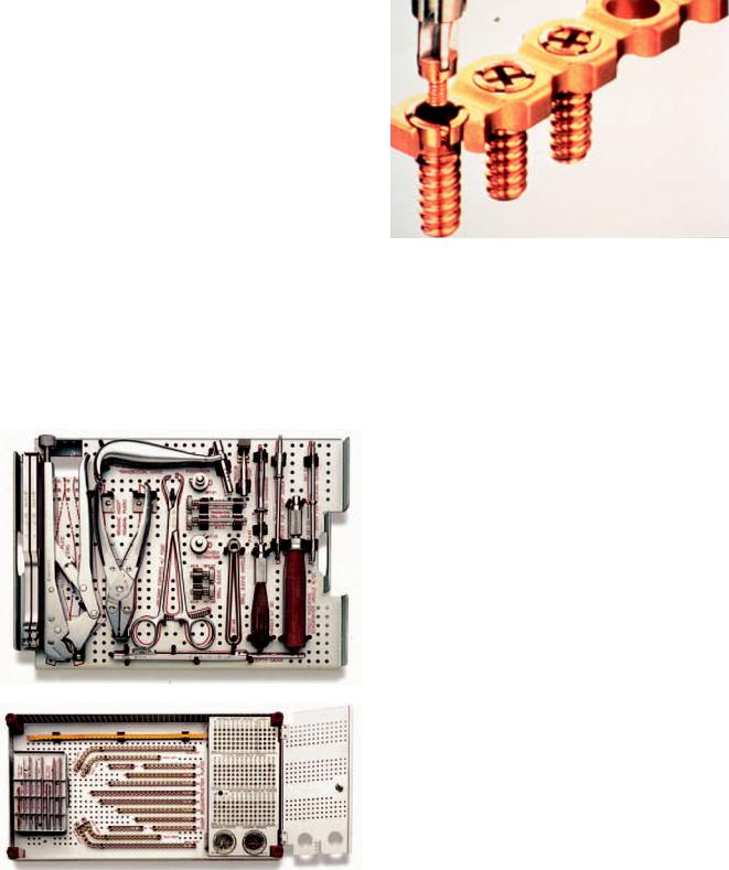
FIGURE 22.23 Locking screw insertion in THORP screw head case. (Courtesy of Synthes Maxillofacial, Paoli, PA)
screws 8-, 12-, 14-, 16-, 18-, and 20-mm lengths which are not generally intended for removal. 1.8 mm titanium locking screws 5 mm in length (Figure 22.23) are inserted into the head of the 4.0 mm titanium solid and hollow THORP screws in order to lock the plate to these bone penetrating screws. The corresponding drill bits to be used are 3.0 mm 130 mm, which after the hole is prepared is then widened with a 4.0 mm tap. The implants come as 4.0 Titanium THORP Reconstruction Plates Straight (10, 12, 14, 16, 20, and 24 holes) (Figure 22.22b), 4.0-mm Titanium THORP Reconstruction Plates, Angled 5 15 (20 holes) Right and Left, and 4.0 Titanium THORP Reconstruction Plates, and Angled 6 24 (30 holes) Right and Left Corresponding bending templates are also available for these plates. Additional instruments include the 3.0-mm Drill Guide for 4.0-mm screws to ensure perpendicular screw placement (Figure 22.22a) 4.5-Bending Inserts are for use within the plate holes to prevent deformation during bending and are removed with a corresponding Bending Insert Removal Pliers. Other instruments include a Tap for 4.0 mm Screws, Cruciform Screwdriver Shaft, Self Retaining for 4.0 mm Titanium THORP Screws, Cruciform Screwdriver Shaft for 1.8-mm Titanium Locking Screw, Conical Extraction Screw, 4.5-mm Reamer for Titanium THORP plates (to redefine plate holes following bending), and Bending Irons (2), Depth Guide, handle with Quick Coupling (1), Drill Guide Handle (1), Torque Indicating Screwdriver Handle with Quick Coupling (1), and Transbuccal Instruments.
Mandible Fix Bridge
FIGURE 22.22 4.0-mm Titanium Hollow Screw Reconstruction Plate (THORP) Set within graphic case. (a) Lift out tray with instruments at top. (b) Implants, screws, drills, taps, reamer, and screwdriver shafts at bottom of graphic case. (Courtesy of Synthes Maxillofacial, Paoli, PA)
Indications: Mandibular tumor and resective surgery.
This fixation device allows the remaining mandibular segments to be maintained in their preoperative positions following the resection of an anterior mandibular segment in order to permit the application of a THORP, microvascular, or
278
FIGURE 22.24 The Mandible FixBridge assembly in place prior to partial anterior resection of the mandible. (Courtesy of Synthes Maxillofacial, Paoli, PA)
J. Prein and A.M. Greenberg
FIGURE 22.26 Universal Trocar System Insert B system tray. (Courtesy of Synthes Maxillofacial, Paoli, PA)
locking reconstruction plate with or without immediate bone grafting (Figure 22.24). The device is placed prior to resection and then the Mandible FixBridge assembly is removed to allow resection, after which the device is reapplied and an appropriate THORP, microvascular, or locking reconstruction plate is contoured and fixated.
FIGURE 22.25 Universal transbuccal instrumentation with trocar system and ratcheting screwdriver. (Courtesy of Synthes Maxillofacial, Paoli, PA)
The Universal Trocar System
This is a comprehensive system supporting all transbuccal surgical applications for the placement of 2.0-3.0 mm screws (Figure 22.25). It contains (Figure 22.26) 2.0-mm and 2.4- mm cannulas and obturators, handle size specific color coded drill guides for 2.4-mm cannula: 1.8-mm, 1.8-mm DCU Neutral, 1.8-mm DCU compression, 1.8-mm threaded, 2.4-mm threaded, 1.8-mm insert (lag screw), 2.4-mm and 2.0-mm cannula: 1.5-mm. Cheek retractors come as the malleable C-re- tractor cheek retractor rings and cheek retractor blades. The malleable C-retractor and cheek retractor blades can rotate.
Ratcheting Screwdriver
The ratcheting screwdriver is used for the manual placement of screws using a swivel mechanism that allows independent
FIGURE 22.27 Ratcheting screwdriver. (Courtesy of Synthes Maxillofacial, Paoli, PA)
22. AO/ASIF Mandibular Hardware |
279 |
FIGURE 22.28 Battery powered screwdriver system. (Courtesy of Synthes Maxillofacial, Paoli, PA)
movement of the handle for forward and reverse ratchet, as well as for rigid use (Figure 22.27). The hex coupling allows quick connection to the screwdriver blades for 1.5-mm, 2.0- mm, 2.4-mm, and 3.0-mm screws.
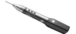
Battery Powered Screwdriver
This battery powered cordless screwdriver (Figure 22.28) uses a rechargeable battery pack. A battery charger recharges 2 battery packs at a time. It is used for the 1.3-mm StarDrive and Cruciform Screwdriver blades and for short and long 1.5- mm/2.0-mm cruciform screwdriver blades.