

- •Preface
- •Acknowledgments
- •Contents
- •Contributors
- •1. Introduction
- •2. Evaluation of the Craniomaxillofacial Deformity Patient
- •3. Craniofacial Deformities: Review of Etiologies, Distribution, and Their Classification
- •4. Etiology of Skeletal Malocclusion
- •5. Etiology, Distribution, and Classification of Craniomaxillofacial Deformities: Traumatic Defects
- •6. Etiology, Distribution, and Classification of Craniomaxillofacial Deformities: Review of Nasal Deformities
- •7. Review of Benign Tumors of the Maxillofacial Region and Considerations for Bone Invasion
- •8. Oral Malignancies: Etiology, Distribution, and Basic Treatment Considerations
- •9. Craniomaxillofacial Bone Infections: Etiologies, Distributions, and Associated Defects
- •11. Craniomaxillofacial Bone Healing, Biomechanics, and Rigid Internal Fixation
- •12. Metal for Craniomaxillofacial Internal Fixation Implants and Its Physiological Implications
- •13. Bioresorbable Materials for Bone Fixation: Review of Biological Concepts and Mechanical Aspects
- •14. Advanced Bone Healing Concepts in Craniomaxillofacial Reconstructive and Corrective Bone Surgery
- •15. The ITI Dental Implant System
- •16. Localized Ridge Augmentation Using Guided Bone Regeneration in Deficient Implant Sites
- •17. The ITI Dental Implant System in Maxillofacial Applications
- •18. Maxillary Sinus Grafting and Osseointegration Surgery
- •19. Computerized Tomography and Its Use for Craniomaxillofacial Dental Implantology
- •20B. Atlas of Cases
- •21A. Prosthodontic Considerations in Dental Implant Restoration
- •21B. Overdenture Case Reports
- •22. AO/ASIF Mandibular Hardware
- •23. Aesthetic Considerations in Reconstructive and Corrective Craniomaxillofacial Bone Surgery
- •24. Considerations for Reconstruction of the Head and Neck Oncologic Patient
- •25. Autogenous Bone Grafts in Maxillofacial Reconstruction
- •26. Current Practice and Future Trends in Craniomaxillofacial Reconstructive and Corrective Microvascular Bone Surgery
- •27. Considerations in the Fixation of Bone Grafts for the Reconstruction of Mandibular Continuity Defects
- •28. Indications and Technical Considerations of Different Fibula Grafts
- •29. Soft Tissue Flaps for Coverage of Craniomaxillofacial Osseous Continuity Defects with or Without Bone Graft and Rigid Fixation
- •30. Mandibular Condyle Reconstruction with Free Costochondral Grafting
- •31. Microsurgical Reconstruction of Large Defects of the Maxilla, Midface, and Cranial Base
- •32. Condylar Prosthesis for the Replacement of the Mandibular Condyle
- •33. Problems Related to Mandibular Condylar Prosthesis
- •34. Reconstruction of Defects of the Mandibular Angle
- •35. Mandibular Body Reconstruction
- •36. Marginal Mandibulectomy
- •37. Reconstruction of Extensive Anterior Defects of the Mandible
- •38. Radiation Therapy and Considerations for Internal Fixation Devices
- •39. Management of Posttraumatic Osteomyelitis of the Mandible
- •40. Bilateral Maxillary Defects: THORP Plate Reconstruction with Removable Prosthesis
- •41. AO/ASIF Craniofacial Fixation System Hardware
- •43. Orbital Reconstruction
- •44. Nasal Reconstruction Using Bone Grafts and Rigid Internal Fixation
- •46. Orthognathic Examination
- •47. Considerations in Planning for Bimaxillary Surgery and the Implications of Rigid Internal Fixation
- •48. Reconstruction of Cleft Lip and Palate Osseous Defects and Deformities
- •49. Maxillary Osteotomies and Considerations for Rigid Internal Fixation
- •50. Mandibular Osteotomies and Considerations for Rigid Internal Fixation
- •51. Genioplasty Techniques and Considerations for Rigid Internal Fixation
- •52. Long-Term Stability of Maxillary and Mandibular Osteotomies with Rigid Internal Fixation
- •53. Le Fort II and Le Fort III Osteotomies for Midface Reconstruction and Considerations for Internal Fixation
- •54. Craniofacial Deformities: Introduction and Principles of Management
- •55. The Effects of Plate and Screw Fixation on the Growing Craniofacial Skeleton
- •56. Calvarial Bone Graft Harvesting Techniques: Considerations for Their Use with Rigid Fixation Techniques in the Craniomaxillofacial Region
- •57. Crouzon Syndrome: Basic Dysmorphology and Staging of Reconstruction
- •58. Hemifacial Microsomia
- •59. Orbital Hypertelorism: Surgical Management
- •60. Surgical Correction of the Apert Craniofacial Deformities
- •Index
51
Genioplasty Techniques and Considerations for Rigid Internal Fixation
Frans H.M. Kroon
Genioplastic corrective surgery has been used for many years.1,2 Owing to the improvement of fixation techniques with plates and screws,2 as in fracture treatment, reconstructive and corrective bone surgery has become considerably more predictable than was possible when wire osteosyntheses were used. In this chapter, the advantages of stable fixation of genioplasties will be described. Genioplastic surgery can be defined in two ways. First, it is an active surgical procedure that is either restricted to the site of the chin bone area or used in combination with other surgical corrective procedures in the mandible. Second, it can also be a passive surgical procedure in the sense that it is an effect of other facial corrective surgery (e.g., a mandibular setback or advancement in combination with osteotomies of the midface).
Genioplasty can be used for esthetic reasons alone, or it can be considered in relation to and in combination with facial corrections for other functional reasons.
Both active and passive genioplastic surgery always requires thorough evaluation of the facial skeleton and associated soft tissues, and careful prediction planning is necessary to achieve a satisfactory esthetic result.3,4
Anatomical Considerations
Eachindividualanatomicalconfigurationwilldeterminethesurgical possibilities for genioplasty, and it is worthwhile to include a few remarks on the anatomy of the chin area. Embryologically, the chin bone, or symphyseal area, is developed by fusion of the two halves of the mandible in the midline of the face.
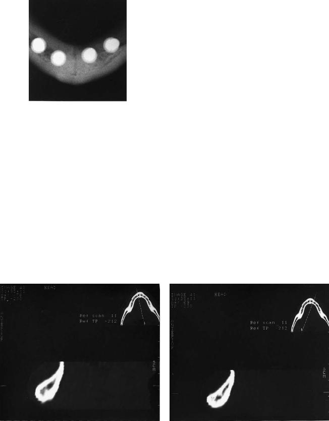
Although even in adults (Figure 51.1) there can still be radiologic evidence of the symphyseal midline, functionally the chin-bone area may be considered as a continuous structure of the mandible.
The functional “borders” of the chin area can be described as follows:
1.A very solid cortical bone ridge as part of the mandibular inferior border ventrocaudal creates the chin point known as the mental protuberance just lateral to which the men-
tal tubercles are formed. These support the soft tissues of the chin area and determine the cosmetic appearance.
2.In the vertical, or coronal, direction, the chin area is limited by the root apices of the lower incisors and canines.
3.The width in the buccolingual direction is determined by the amount of bone marrow and the thickness of the lingual and buccal cortical bone layers. It is also very closely related to the dimensions of the roots of these teeth. In cases of agenesis, there is even a striking minimum of spongeous bone between the two cortical layers, which fuse to the top of the alveolar process (Figure 51.2).
4.In the lateral direction, the chin-area border is determined by the length of the roots of the lower canine and first premolar and the position of the mental foramen. With respect to this, however, one has to realize that in the mandibular canal the alveolar nerve runs slightly frontocaudally from the mental foramen before it turns back and upward to leave the foramen as the mental nerve. Before doing so, a frontal branch occurs, which in many genioplasties will be surgically violated.
In designing and planning the genioplasty, it is important to note the position and function of some other landmarks:
1.The origins/insertions of the geniohyoid and genioglossus muscles
2.The insertion of the median raphe of the mylohyoid muscle
3.The insertions and configuration of the mental and mentolabial muscles at the frontal site
Vascular supply of the chin bone in a genioplasty procedure is sufficiently preserved by leaving the caudal side attached to the soft tissues of the chin. In studies of long-term results, bone apposition is seen at point B and slight resorption occurs at pogonion.
Analysis of Facial Anatomy
To evaluate and determine the position of the chin, several methods of facial analysis are available.5–12
623
624
FIGURE 51.1 Occlusal view of symphyseal area of 53-year-old man, edentulous for 30 years. Clear evidence of symphyseal midline septum (white spots represent implants).
It is important to study both the bony and soft tissue configurations. The final interpretation of measurements should also take into consideration the relative importance of the nasolabial angle, the length of the upper lip, the extent of visibility of parts of the dentition, the labiomental fold in relation to the position of teeth, and the curvature of the chin to the throat area.
In addition to the evaluation of the lateral x-rays and photographs, it is very important to study the direct frontal appearance of the chin. In particular, the position and functional effects of mental muscles may determine the design of the genioplasty. Furthermore, it is important to realize that the effects of profile changes in the chin area are quite different in the horizontal and vertical directions depending on the type and direction of the osteotomies. In horizontal augmentation procedures, different ratios between soft tissue and hard tis-
a
F.H.M. Kroon
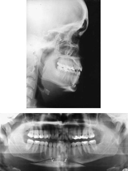
sue are mentioned, from 60% to 75%.13,14 In reduction procedures, there is always the danger of weakening of the soft tissues of the chin. Stable internal fixation has been shown to give improved reliability of the clinical results.13–15 Likewise, the final outcome of passive chin surgery as an effect of mandibular advancement or setback procedures is closely related to the extent of horizontal and vertical vectors of the change in position of the chin. Forward or backward positioning along the line of occlusion will always be followed by the chin. However, correction of an Angle class II/1 (deep bite) will at the same time lengthen the vertical height in the chin area, straighten the mentolabial fold, and still move the chin forward less than the incisor region (Figure 51.3). This relative clockwise rotation of the chin is frequently an adequate correction of an otherwise undesired forwardpositioning of the chin.
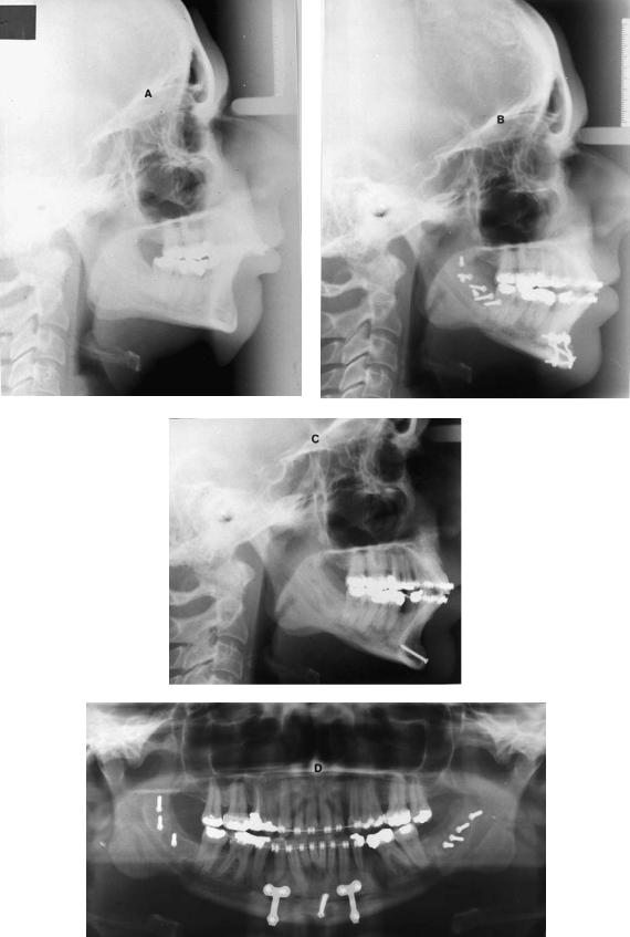
Figure 51.4 shows another clinical result of a passive genioplasty. Severe Angle class II/1 (deep bite) was corrected by mandibular advancement (sagittal split osteotomy) in conjunction with Köle osteotomy for surgical intrusion of the incisor segment (anterior mandibular segment from cuspid to cuspid), stable fixation with positioning screws in the mandibular angle, and the placement of two 2.0-mm miniplates and one central lag screw (2.0 mm) in the Köle segment.
Indications and Classifications
In general, the indication for a genioplasty is determined by the need to maintain or to move the chin bone area of the mandible by surgical intervention into such a position that it is in harmony with the references of hardand soft-tissue analyses of a particular patient.
b
FIGURE 51.2 Photograph of CT imaging of vertical configuration of symphyseal area left (a) and right (b) of midline in a 21-year-old man with agenesis of the dentition. Thick cortical layers, hardly any marrow, and concave configuration are at the anterior side.
51. Genioplasty Techniques and Considerations for Rigid Internal Fixation |
625 |
a |
|
|
|
|
|
b |
|
|
|
|
|
|
|
|
|
|
|
|
|
|
|
|
|
|
|
|
|
|
|
|
|
|
|
|
c |
|
|
|
|
|
d |
|
|
|
|
|
|
|
|
|
|
|
|
|
|
|
|
|
|
|
|
|
|
|
|
|
|
|
|
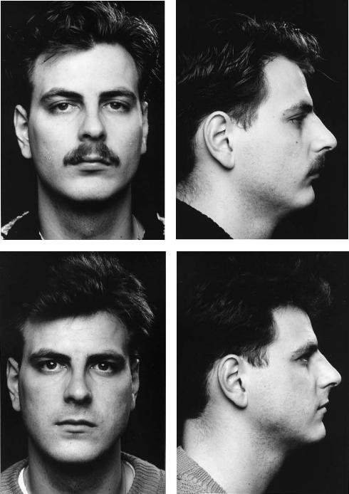
FIGURE 51.3 Clinical example of passive genioplasty. Presurgical and postsurgical photographs of a 22-year-old man with Angle class II/1 (deep bite) corrected by surgical advancement of the mandible (bilateral sagittal split osteotomy). Note the improvement of the chin
position, lengthening of the anterior height, and stretching of the inferior labial fold. (a) Presurgical frontal view. (b) Presurgical in profile. (c) Postsurgical frontal view. (d) Postsurgical in profile.
626 |
F.H.M. Kroon |
a |
b |
c
d
51. Genioplasty Techniques and Considerations for Rigid Internal Fixation |
627 |
TABLE 51.1 Classification for genioplasties related to the main direction of change in position of the chin.
1.Horizontal a. Backward b. Forward
2. Vertical |
a. Upward |
b.Downward
3.Lateral to correct asymmetry
4.Combinations
TABLE 51.2 Classification for genioplasties related to the main clinical change in appearance.
1.Augmentation a. Horizontal
b.Vertical
2. Reduction |
a. Horizontal |
b.Vertical
3.Correction of asymmetry
4.Combinations
Classifications for genioplasties are most practical if they are related either to the direction of the change in position of the chin (Table 51.1) or to the proposed clinical change in appearance (Table 51.2).
In the case of asymmetry, an anteroposterior x-ray and a submentovertex x-ray should be taken and analyzed to measure the discrepancies and to determine the extent of bony corrections. Several methods have been described.20
Prediction Measurements |
Surgical Approach |
Measurements for prediction can be drawn on lateral cephalometric radiograph tracings. This method gives acceptable and sufficient information about the surgical possibilities in the hard tissue and the clinical effect at the site of the soft tissue.6,16,17 In recent years, three-dimensional computerized hardand soft-tissue prediction programs have become available.18
After analysis of the lateral cephalometric x-ray, the required transposition of the bony chin can be drawn and measured (Figure 51.5). To have a controlled clinical prediction, it is wise to correlate the drawing to the position of the lower incisor. An equilateral rhomboid parallelogram can be constructed by drawing crosspoint X between the lower incisor line and an occlusal line connecting the tips of the molars, cuspids, and incisors. Parallel to this occlusal line, the baseline is drawn from where the incisor line crosses the inferior mandibular border (point Y). The length XY is used as measure for the four sides of the parallelogram. The next step is to choose how to divide the angle between baseline and incisorline. In case of the bisector, the transposition effects in both the horizontal and vertical directions are of equal length. If the inclination is less steep (i.e., ), the horizontal effect will be greater than the vertical effect. If the inclination is steeper (i.e., ), the vertical effect is bigger than the horizontal effect. Earl and Foster described an apparatus that can be used during surgery to maintain the orientation with the planned angle during bone sawing. Depending on the required transposition, the angle of the inclination can be chosen and the horizontal and vertical coordinates can be measured.19
A genioplasty procedure can be performed completely intraorally. Preferably, the mucosal incision lies in the nonattached gingiva deep enough in the vestibular sulcus to have enough soft tissue to close the incision afterwards. Laterally, the incision should be superior to the mental nerve. Generally, it is wise to first identify the mental foramen and preserve its nerve through a safe and correct orientation of the osteotomy. Incisions that extend further out in the labial part of the lateral vestibule tend to cross the fine branches of the mental nerve.
The periosteum should always be kept attached to the frontal part of the chin to maintain sufficient vascular blood supply. The periosteum should be kept in good condition to
FIGURE 51.4 Clinical result of a passive genioplasty procedure to correct a severe Angle class II/1 malocclusion. (a) Presurgical lateral x-ray. (b) Postsurgical situation after sagittal split procedure in conjunction with segmental intrusion of the lower cuspids and incisors.
(c) Postsurgical situation after 6 months. Hardware removed except for the central lag screw. (d) Orthopantomogram to show the position of plates and screws.
FIGURE 51.5 Line drawing of construction of parallelogram to orient the preferable direction of osteotomy line and required transposition of genial bone fragment. (Incisor line crosses occlusal line at point X and the inferior border at point Y. If , vertical and horizontal transpositions are of equal length. If , the horizontal transposition increases. If , the vertical transposition increases.) For further explanation see text.
628
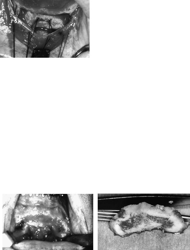
FIGURE 51.6 Photograph of mattress-sutures to close in layers by stepping the periosteal layer directly to the bone surface; picture shows the situation just before tightening the sutures.
use for final closure procedures in layers. To achieve this type of closure, it can be helpful to split the periosteal and mucosal layers more extensively. Figure 51.6 shows traction mattress-sutures to step the periosteum directly to the bone.
Complete degloving procedures are unnecessarily dangerous and have lead to necrosis and infections.21,22
Surgical Procedures
After a straight full mucoperiosteal incision or after stepwise incisions and separation of mucosal and periosteal layers, the periosteum at both sides of the incision is elevated just enough to provide sufficient bone surface to carry out the bone cut. The frontal segment of the chinbone can always be left attached to the periosteum. With references to the position of the mental foramen, a sliding osteotomy can be carried out according to the chosen angle to the bone surface (related to the position of the lower incision).
To indicate the exact location of a sliding osteotomy, some
a
F.H.M. Kroon
landmarks can be made with a small, round drill. The final cutting can be carried out with a thin saw blade. If a more complicated design is planned, as in rotation and reduction procedures, landmarks made by means of a small, round burr are even more important. Anteroposterior reduction that cannot be achieved by a sole sliding osteotomy and translation of the segment should be realized by an osteotomy. If necessary, such an osteotomy can be designed as a wedge to allow additional rotation of the frontal segment around a transverse axis. Figure 51.7 shows the clinical situation after removal of an intermediate bone segment. Note the relative thickness of the cortex suitable for fixation by means of plates and screws.
The chinbone should never be reduced by simply cutting off a frontal segment. The reduction effect is minimal because of the lack of support in transposition of the soft tissues. Moreover, due to the excision of the bone segment, the soft tissues are weakened in a very undesirable way.23
Fixation Techniques
Because plates and screws are available in an extensive variety of sizes and configurations, the use of wire osteosynthesis has lost its justification as a fixation technique in genioplasty procedures. Figure 51.8 shows the result of insufficient support and positioning of a genial segment fixed by wire osteosynthesis. The locations of the wire osteosyntheses are quite the same if plate fixation is carried out (Figure 51.13g). Similar to the stabilization of segments and fragments in fracture treatment,1,24 the technique of lag screw fixation is very useful and relatively easy to perform in genioplasty procedures. Precision in position and drilling procedures is essential.25,26
Stable fixation by means of plates, screws, or a combination of the two contributes to predictable surgical results regarding positioning, avoids undesired resorption effects due to instability, and allows relative extensive distances of advancements or transposition procedures.
b
FIGURE 51.7 (a) Frontal view of reduced chin area. (b) Frontal view of resected bone segment. Note the relative thickness of the cortical layers, suitable for proper stable fixation.
51. Genioplasty Techniques and Considerations for Rigid Internal Fixation |
629 |
a
b
FIGURE 51.8 Insufficient position and support of a reduced chin segment fixed by wire osteosyntheses. (a) Lateral skull x-ray. (b) Orthopantomogram.
Craniofacial osteotomy instrumentation sets usually contain four sizes of plates. The regular (mandibular) 2.4 system has screw diameters of 2.4 mm. Miniplate systems 2.0 and 1.5 have screw diameters of 2.0 and 1.5 mm, respectively, including additional 2.4-mm screws as “emergency screws.” Microplate systems 1.0 and 1.2 have screw diameters of 1.0 and 1.2 mm, respectively.
Systems 2.0 and 1.5 are the most convenient and practical for fixation of genioplasty segments. The strength of the 2.0 screws is sufficient to stabilize segments using either three separate lag screws or a combination of one screw in the central part and miniplates or microplates at both sides. The feasibility of screws as the sole means of fixation, using either as a lag screw or a positioning screw as shown in Figure 51.9, depends entirely on the type and direction of the osteotomy line (Table 51.3).
The use of the lag screw technique is only possible if enough holding power in the cortical layers can be achieved. If this cannot be realized, the transposition gap can better be bridged with plates with the preferred minimum of at least two monocortical screws on either side of the osteotomy line.
The 2.4-mm size is usually suitable to achieve initial segment stability. Infrequently, a 2.7-mm screw emergency will be required.
Fixation Procedures
Precise positioning of the genial segment is essential for a well-defined clinical result. A well-controlled sawing procedure results in an accurate translation of the planning and analysis to the clinical situation, and permits an exact trans-
630 |
F.H.M. Kroon |
a |
b |
c |
d |
e |
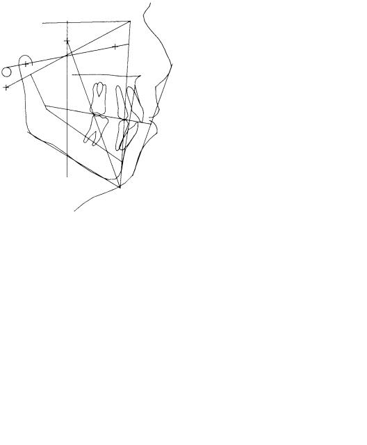
FIGURE 51.9 Photographs of (a) preand (b) postsurgical situation of a chin augmentation achieved by a sliding osteotomy according to the prediction described in Figure 51.5. (a) Presurgical situation.
position and fixation technique. Midline references should be marked on the bone segment. Even extraoral orientation on a line such as the Frankfurt horizontal can be very helpful.
When introducing lag screws, the technical rules of preparation should be strictly followed:
1.Preparation of the gliding hole in the genial segment. If necessary, gently adjust the cortical surface for an exact fit and avoid any sliding of the screwhead.
2.Prepare the opposite traction hole in the mandible using a centering drill guide to achieve coaxial preparation of the holes.
(b) Postsurgical situation. (c) Presurgical tracing. (d) Postsurgical tracing. (e) The combination of (c) and (d). Dotted lines are presurgical. (Line drawings in (c,d,e) courtesy Dr. P.E. Swartberg)
3.Measure the required screw length.
4.Pretap the traction hole, if a nonself-tapping screw is to be used.
5.Insert and position the screw.
The need for pretapping is mainly determined by the thickness and the number of cortical layers to pass. Experimental work27,28 has shown that length of the pathway in the cortex of more than 3 mm requires pretapping. Additionally, it is important to realize that in case of using or passing through more cortical layers the length of the screw is critical and requires proper preparation of the drill holes.

51. Genioplasty Techniques and Considerations for Rigid Internal Fixation |
631 |
TABLE 51.3 Preferable type of fixation and clinical effect of transposition of genial segment related to the inclination of the (sliding) osteotomy line to the incisor line and occlusal line (see Figure 51.5).
|
|
Direction of |
|
|
|
Angulation of |
segmental |
|
Preferable type |
Type of genioplasty |
osteotomy line |
transposition |
Clinical effect |
of fixation |
|
|
|
|
|
A. Without bone reduction |
I. Parallel to |
a. Upward |
Vertical reduction |
Lag screw |
|
incisor line |
b. Downward |
Vertical augmentation |
Lag screw and/or miniplates |
|
II. Bisector |
a. Upward |
Vertical reduction horizontal augmentation |
Lag screw |
|
|
b. Downward |
Vertical augmentation horizontal reduction |
Miniplates |
|
III. Parallel to |
a. Forward |
Horizontal augmentation |
Miniplates |
|
occlusal line |
b. Backward |
Horizontal reduction |
Miniplates |
B. With segment excision |
I. Parallel to |
a. Upward |
Vertical horizontal reduction |
Lag screw |
|
incisor line |
b. Downward |
Vertical augmentation horizontal reduction |
Lag screw and/or miniplates |
|
|
c. No sliding |
Horizontal reduction |
Lag screw |
|
II. Bisector |
a. Upward |
Vertical reduction |
Lag screw |
|
|
b. Downward |
Vertical augmentation horizontal reduction |
Miniplates |
|
|
c. No sliding |
Horizontal reduction |
Lag screw |
|
III. Parallel to |
a. Forward |
Horizontal augmentation vertical reduction |
Miniplates |
|
occlusal line |
b. Backward |
Horizontal reduction vertical reduction |
Miniplates |
|
|
c. No sliding |
Vertical reduction |
Miniplates |
C. With segment interposition |
I. Parallel to |
a. Upward |
Horizontal augmentation vertical reduction |
Lag screw |
|
incisor line |
b. Downward |
Horizontal augmentation vertical augmentation |
Lag screw and miniplates |
|
|
c. No sliding |
Horizontal augmentation |
Lag screw |
|
II. Bisector |
a. Upward |
Horizontal augmentation vertical reduction |
Lag screw |
|
|
b. Downward |
Vertical augmentation |
Lag screw and miniplates |
|
|
c. No sliding |
Horizontal vertical augmentation |
Lag screw |
|
III. Parallel to |
a. Forward |
Horizontal vertical augmentation |
Miniplates |
|
occlusal line |
b. Backward |
Horizontal reduction vertical augmentation |
Miniplates |
|
|
c. No sliding |
Vertical augmentation |
Miniplates |
|
|
|
|
|
Rotation and Interposition
of Bone Fragments
Augmentation procedures sometimes need interposition of segmental fragments or additional bone transplants. Generally, the technique of fixation of such configurations of genioplasties is not different from the simpler sliding procedure. The position of the segments should be stabilized during the hole preparation procedure to achieve the planned clinical result.
The space created in the vicinity of point B can easily be filled in with spongeous bone transplants or a cortical fragment from the osteotomy procedure can be used for that purpose. Preferably, stable fixation of such fragments should be realized by using the lag screw technique. Miniscrews 1.5- mm diameter or even the 1.0-mm microscrews can provide adequate stability. The surgical steps of such a procedure of slight rotation and interposition in a case of chin augmentation is shown in Figure 51.10. The radiographic evidence of positioning and consolidation is shown in Figure 51.11. The clinical appearance is shown in Figure 51.12. Lateral defects at the inferior border can also be considered to be filled in with bone particles and eventually combined with artificial bone fragments (covered by resorbable membranes). Correction of asymmetries should include thorough orientation of facial and dental midlines. Rigid fixation by means of lag screws, miniplates, or a combination, is even more important
in these more complicated corrections. Wedge-type excisions and propeller-type segment inversions to correct asymmetries have been described.20 Midline splits for widening may also be considered.
Complications and Solutions
Overdrilling of Holes
In the case of overdrilling of holes, emergency screws that correspond to the planned type of screws should be available; that is, 1.2 (1.0), 1.5 (1.2), 2.0 (1.5), 2.4 (2.0), or 2.7 (2.4). If the proposed design of lag screws fails, monocortical fixation of well-adapted miniplates (or even microplates) should be the proper solution. During preparation of drill holes, careful cooling and rinsing procedures should be followed.
Soft Tissue Closure
With augmentation, inadequacy of soft tissues for closure in layers can be easily prevented by choosing a stepwise mucosal/periosteal incision and additional splitting of both layers from each other before closing in layers.
In the case of reduction, abundance of tissue could require shortening the soft tissue of the lower lip by reducing the buccal mucosa. Care must be taken in reapproximating the mentalis muscles, which at times may require bony suspension.
632 |
F.H.M. Kroon |
a |
b |
c |
d |
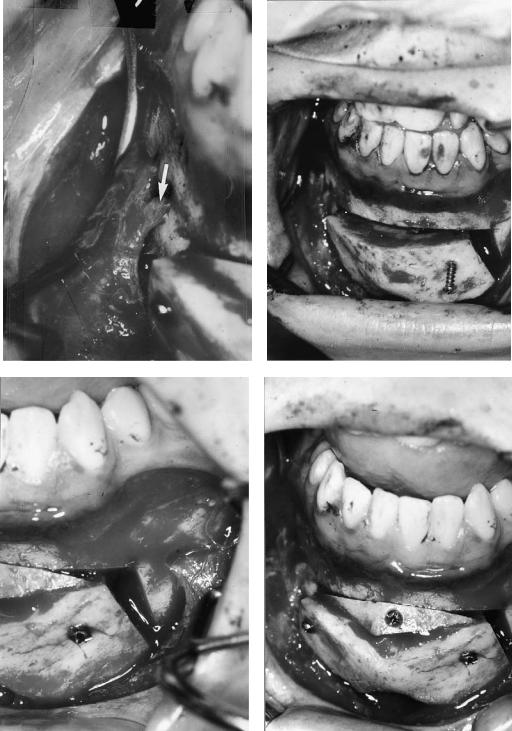
FIGURE 51.10 Surgical steps of fixation of frontal genial segment, slightly rotated around a transverse axis. (a) Note the position of the mental nerve (see arrow). (b–d) Positioning of the 2.0 fixation lag
screw and the fixation and stabilization of a cortical fragment to fill the gap at point B.
51. Genioplasty Techniques and Considerations for Rigid Internal Fixation |
633 |
a |
b |
c |
d |
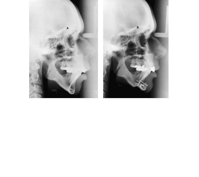
FIGURE 51.11 Lateral x-rays of the patient described in Figures 51.10 and 51.12. (a) Presurgical. (b) Direct postsurgical. (c) Three months postsurgical. (d) Consolidation after 15 months. No signs of resorption around screwheads (titanium screws).
634 |
|
|
|
F.H.M. Kroon |
a |
|
|
|
b |
|
|
|
|
|
|
|
|
|
|
|
|
|
|
|
|
|
|
|
|
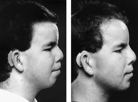
FIGURE 51.12 Clinical photographs of the patient described in Figures 51.10 and 51.11. (a) Presurgical. (b) Postsurgical after nose correction (courtesy Dr. J.B. de Boer) and after chin augmentation. (c)
Presurgical tracing. (d) Postsurgical tracing. (e) Combination of (c) and (d). Dotted line is presurgical. [(c,d,e,) Courtesy Dr. P.E. Swartberg]
Wound Dehiscenses
Wound dehiscense mostly occurs because of insufficient oral hygiene postoperatively or from a lack of temporary support by bandages. Reapplication of extraoral bandages and thorough cleaning instruction will solve these problems. Regular intensive dental hygiene should be advised and can be supported by rinsing the mouth with salt water or chlorohexidine gluconate rinses.
Nerve Damage
The best solution to manage nerve damage is through prevention. Mucosal incision design superior to the mental foramen avoids unneccesary division of small extensions of the mental nerve. Temporary hypoesthesia is expected in all cases, and the patient should be advised. Return of sensation of damaged mental nerves is very difficult to predict and should not be promised.
Infections
To prevent infection, generally short prophylactic application of antibiotics (24 hours) should be sufficient. Infections, rarely occur, and most probably will be due to instability of the segments and loose hardware. Removal of loose hardware and reapplication of internal fixation is the treatment method of choice.29 Only in the case of abscess formation is extensive empirical antibiotic therapy and culture and identification of the bacteria necessary.
Cosmetic Failures
Patients’ final satisfaction with the cosmetic results can be a very delicate matter, especially when a genioplasty is done for cosmetic improvement only (see Figure 51.13). However, cosmetic changes that result from major facial corrections, such as extensive orthognathic surgery for functional reasons, also include risks for patient dissatisfaction. It has been pointed out that psychological aspects may play an important role as a predisposition to the development of jaw dysfunction.30 Preoperative attention to patient expectations and
51. Genioplasty Techniques and Considerations for Rigid Internal Fixation |
635 |
c |
d |
e
FIGURE 51.12 Continued.
636 |
|
F.H.M. Kroon |
a |
|
b |
|
||
|
|
|
c |
d |
e |
FIGURE 51.13
51. Genioplasty Techniques and Considerations for Rigid Internal Fixation |
637 |
f
g
h
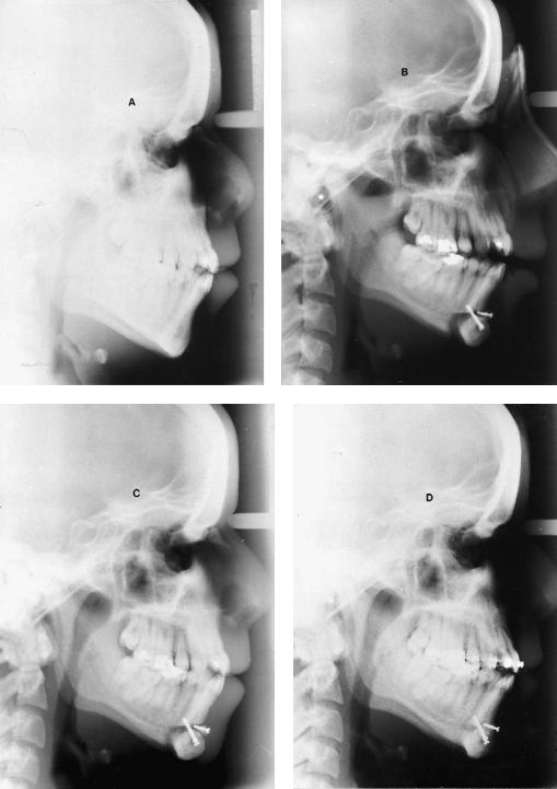
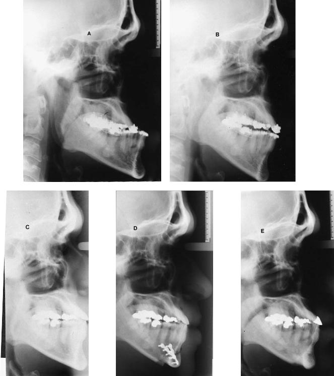
FIGURE 51.13 Continued. X-rays of Hindustan man (30 years old at time of first surgery). Angle class III malocclusion skeletal hypodevelopment of the maxilla (with protrusion of the incisors) and prognathism of the mandible corrected by vertical ramus osteotomy. (a) Lateral x-ray presurgical. (b) Lateral x-ray postsurgical (10 weeks).
(c) Lateral x-ray postsurgical (4 years and 3 months) used as presurgical to chin surgery. (d) Lateral x-ray postsurgical to genioplasty after 1 day. (e) Lateral x-ray postsurgical (7 years and 7 weeks) after vertical ramus osteotomy, and (2 years and 9 months) after genioplasty. (f) Orthopantomogram postsurgical (6 weeks). (g) Orthopantomogram 1 day after chin surgery. (h) Orthopantomogram
(7 years and 7 weeks) after vertical ramus osteotomy and (2 years and 9 months) after genioplasty, following removal of hardware.
Note 1: At present, patient is again seeking treatment for the hypodevelopment of the infraorbital regions. In the past, the retrognathism of the maxilla and the infraposition of the malar bones was considered to be acceptable. The patient is still satisfied with the position of the chin after his setback operation and genioplasty. Reevaluation and facial analysis will be combined in consultation with a psychologist.30 Note 2: The notches in the inferior border related to the genioplasty have been mainly remodeled by bone apposition.
638
desires is important and can be helpful to prevent unnecessary complications.
Conclusion
Although a genioplasty seems to be a simple operation, the translation of the treatment plan into a satisfying and predictable long-term, stable result can be challenging. Lengthening or augmentation procedures are much safer and more predictable in relation to the soft tissue appearance than reduction procedures.
Shortening and reduction always include the risk of ptosis or weakening of the soft tissue appearance of the chin. However, hyperactivity or hyperfunction of muscle groups such as the mental muscles can be positively influenced. Techniques of rigid internal fixation have brought a major improvement of the feasibility and predictability of genioplasties by bone surgery.
References
1.Leonard MS. The use of lag screws in mandibular fractures.
Otolaryngol Clin North Am. 1987;20(3):479–493.
2.Spiessl B. Internal Fixation of the Mandible. A Manual of AO/ASIF Principles. Berlin; Springer-Verlag; 1989.
3.McBride KL, Bell WH. Chin surgery. In: Bell WH, Proffit WR, White RP, eds. Surgical Correction of Dentofacial Abnormalities. Philadelphia: Saunders; 1980:1216–1279.
4.Proffit, WR. Treatment planning: the search for wisdom. In: Profitt WR, White RP, eds. Surgical Orthodontic Treatment.
Boston: Mosby Year Book; 1991:142–191.
5.Gonzalez Ulloa M. Quantitative principles in cosmetic surgery of the face. Plast Reconstr Surg. 1963;29:2.
6.McNamara JA Jr. A method of cephalometric evaluation. Am J Orthod. 1984;86:449–468.
7.Moorrees CFA, Kean MR. Natural head position: a basic consideration for analysis of cephalometric radiographs. Am J Phys Anthropol. 1958;16:213–234.
8.Ricketts RM. Perspectives in the clinical application of cephalometrics. Angle Orthod. 1981;51:115–150.
9.Sassouni VA. A classification of skeletal facial types. Am J Orthod. 1969;55:109–123.
10.Solow B, Tallgren A. Natural head position in standing subjects.
Acta Odontol Scand. 1971;29:591–607.
11.Steiner CC. Cephalometrics for you and me. Am J Orthod. 1953;39:729.
12.Steiner CC. The use of cephalometrics as an aid to planning and
F.H.M. Kroon
assessing orthodontic treatment. Am J Orthod. 1960;46:721– 735.
13.Davis WJ, Davis CL, Daly BW. Long-term bony and soft tissue stability following advancement genioplasty. J Oral Maxillofac Surg. 1988;46:731.
14.Polido WD, De Clairefont Regis L, Bell WH. Bone resorption, stability, and soft-tisuue changes following large chin advancements. J Oral Maxillofac Surg. 1991;49:251–256.
15.Sik Park H, Ellis E, Fonseca RJ, Reynolds ST, Mayo KH, Arbor A. Oral surgery. A retrospective study of advancement genioplasty. Oral Surg Oral Med Oral Pathol. 1989;67:481.
16.Popovich F, Thompson GW. Craniofacial templates for orthodontic case analysis. Am J Orthod. 1977;71:406–420.
17.Walker R. Dentofacial Planner; User Manual Dentofacial Planner Software. Toronto; 1988.
18.Walker R. Dentofacial Planner; User Manual Dentofacial Planner Software 6.5. Toronto; 1995.
19.Earl PH, Foster M. A new technical aid for genioplasties. Abstracts of the 12th Congress of EACMFS (nr. 125). J Craniomaxillofac Surg. 1994;22:43.
20.Thomson ERE. Sagittal genioplasty: a new technique of genioplasty. Br J Plast Surg. 1985;38:70–74.
21.Ellis E, Dechow PC, McNamara JA Jr. Advancement genioplasty with and without soft tissue pedicle. An experimental investigation. J Oral Maxillofac Surg. 1984;42:639.
22.Mercuri LG, Laskin DM. Avascular necrosis after anterior horizontal augmentation genioplasty. J Oral Surg. 1977;35:296.
23.Noorman van der Dussen F, Egyedi P. Premature aging of the face after orthognathic surgery. J Craniomaxfac Surg. 1990;18: 335.
24.Frodel JL Jr, Marentette LJ. Lag screw fixation in the upper craniomaxillofacial skeleton. Arch Otolaryngol Head Neck Surg. 1993;119(3):297–304.
25.Ellis E, Ghali GE. Lag screw fixation of anterior mandibular fractures. J Oral Maxillofac Surg. 1991;49(1):13–21.
26.Ilg P, Ellis E. A comparison of two methods for inserting lag screws. J Oral Maxillofac Surg. 1992;50(2):119–123.
27.Bähr W, Stoll P. Pre-tapped and self-tapping screws in children’s mandibles. A scanning electron microscopic examination of the implant beds. Br J Oral Maxillofac Surg. 1991:29.
28.Phillips JH, Rahn BA. Comparison of compression and torque of self-tapping and pretapped screws. Plast Reconstruct Surg. 1989;83(3):447–456.
29.Prein J, Beyer M. Management of infection and nonunion in mandibular fractures. Oral Maxillofac Surg Clin North Am.
1990;2(1):187–194.
30.Hakman ECJ. Psychological aspects of surgical orthodontics. In: Tuinzing DB, Greebe RB, Dorenbos J, van der Kwast WAM, eds. Surgical Orthodontics, Diagnosis and Treatment. Amsterdam: University Press; 1993:108.