

- •Preface
- •Acknowledgments
- •Contents
- •Contributors
- •1. Introduction
- •2. Evaluation of the Craniomaxillofacial Deformity Patient
- •3. Craniofacial Deformities: Review of Etiologies, Distribution, and Their Classification
- •4. Etiology of Skeletal Malocclusion
- •5. Etiology, Distribution, and Classification of Craniomaxillofacial Deformities: Traumatic Defects
- •6. Etiology, Distribution, and Classification of Craniomaxillofacial Deformities: Review of Nasal Deformities
- •7. Review of Benign Tumors of the Maxillofacial Region and Considerations for Bone Invasion
- •8. Oral Malignancies: Etiology, Distribution, and Basic Treatment Considerations
- •9. Craniomaxillofacial Bone Infections: Etiologies, Distributions, and Associated Defects
- •11. Craniomaxillofacial Bone Healing, Biomechanics, and Rigid Internal Fixation
- •12. Metal for Craniomaxillofacial Internal Fixation Implants and Its Physiological Implications
- •13. Bioresorbable Materials for Bone Fixation: Review of Biological Concepts and Mechanical Aspects
- •14. Advanced Bone Healing Concepts in Craniomaxillofacial Reconstructive and Corrective Bone Surgery
- •15. The ITI Dental Implant System
- •16. Localized Ridge Augmentation Using Guided Bone Regeneration in Deficient Implant Sites
- •17. The ITI Dental Implant System in Maxillofacial Applications
- •18. Maxillary Sinus Grafting and Osseointegration Surgery
- •19. Computerized Tomography and Its Use for Craniomaxillofacial Dental Implantology
- •20B. Atlas of Cases
- •21A. Prosthodontic Considerations in Dental Implant Restoration
- •21B. Overdenture Case Reports
- •22. AO/ASIF Mandibular Hardware
- •23. Aesthetic Considerations in Reconstructive and Corrective Craniomaxillofacial Bone Surgery
- •24. Considerations for Reconstruction of the Head and Neck Oncologic Patient
- •25. Autogenous Bone Grafts in Maxillofacial Reconstruction
- •26. Current Practice and Future Trends in Craniomaxillofacial Reconstructive and Corrective Microvascular Bone Surgery
- •27. Considerations in the Fixation of Bone Grafts for the Reconstruction of Mandibular Continuity Defects
- •28. Indications and Technical Considerations of Different Fibula Grafts
- •29. Soft Tissue Flaps for Coverage of Craniomaxillofacial Osseous Continuity Defects with or Without Bone Graft and Rigid Fixation
- •30. Mandibular Condyle Reconstruction with Free Costochondral Grafting
- •31. Microsurgical Reconstruction of Large Defects of the Maxilla, Midface, and Cranial Base
- •32. Condylar Prosthesis for the Replacement of the Mandibular Condyle
- •33. Problems Related to Mandibular Condylar Prosthesis
- •34. Reconstruction of Defects of the Mandibular Angle
- •35. Mandibular Body Reconstruction
- •36. Marginal Mandibulectomy
- •37. Reconstruction of Extensive Anterior Defects of the Mandible
- •38. Radiation Therapy and Considerations for Internal Fixation Devices
- •39. Management of Posttraumatic Osteomyelitis of the Mandible
- •40. Bilateral Maxillary Defects: THORP Plate Reconstruction with Removable Prosthesis
- •41. AO/ASIF Craniofacial Fixation System Hardware
- •43. Orbital Reconstruction
- •44. Nasal Reconstruction Using Bone Grafts and Rigid Internal Fixation
- •46. Orthognathic Examination
- •47. Considerations in Planning for Bimaxillary Surgery and the Implications of Rigid Internal Fixation
- •48. Reconstruction of Cleft Lip and Palate Osseous Defects and Deformities
- •49. Maxillary Osteotomies and Considerations for Rigid Internal Fixation
- •50. Mandibular Osteotomies and Considerations for Rigid Internal Fixation
- •51. Genioplasty Techniques and Considerations for Rigid Internal Fixation
- •52. Long-Term Stability of Maxillary and Mandibular Osteotomies with Rigid Internal Fixation
- •53. Le Fort II and Le Fort III Osteotomies for Midface Reconstruction and Considerations for Internal Fixation
- •54. Craniofacial Deformities: Introduction and Principles of Management
- •55. The Effects of Plate and Screw Fixation on the Growing Craniofacial Skeleton
- •56. Calvarial Bone Graft Harvesting Techniques: Considerations for Their Use with Rigid Fixation Techniques in the Craniomaxillofacial Region
- •57. Crouzon Syndrome: Basic Dysmorphology and Staging of Reconstruction
- •58. Hemifacial Microsomia
- •59. Orbital Hypertelorism: Surgical Management
- •60. Surgical Correction of the Apert Craniofacial Deformities
- •Index
43
Orbital Reconstruction
Beat Hammer
Orbital reconstruction may indicate either the replacement of missing segments of the orbital skeleton, reduction of displaced fragments, or both. The indications for surgical intervention are trauma, posttraumatic deformities, defects after tumor resection, and malformations.1 Despite the considerable differences among these problems, there are commonly applied principles. In this chapter, immediate posttraumatic orbital reconstruction is discussed as a model for orbital reconstruction. The fracture patterns vary considerably in their location as well as in their degree of severity. A formal reconstruction is necessary in the case of severe disruption of the orbital frame or in the presence of a large defect in the orbital walls.
Basic Principles
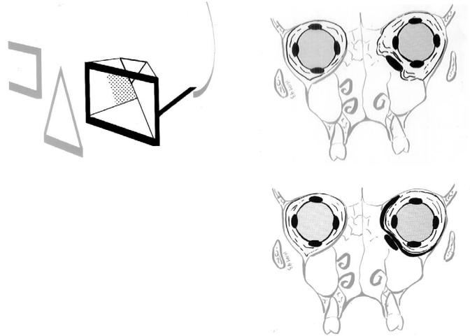
The orbit is a pyramid-shaped structure containing the ocular globe with its motor apparatus. In all situations, the goal of reconstruction is to restore the normal shape and volume. The orbit is composed of seven individual bones. For surgical purposes however, a differentiation between orbital frame and the orbital pyramid, or internal orbit is adequate (Figure 43.1).
The posterior part of the medial wall is an area of special surgical interest and is called the “key area” for the following reasons:
•It is, together with the lateral wall, the main support for the anterior projection of the globe. The function of the two walls has been compared to a pair of cupped hands holding the globe in its forward position.2
•Being a paper-thin structure, it is often damaged in orbital injuries.
•Clinical experience has shown that repair of fractures with an intact “key area” is technically much easier than repair of fractures involving this part of the orbit.3 Therefore, the first step in repair of complex orbital injuries is repair of the key area as described below.
Orbital reconstruction requires adequate exposure, for which complete subperiostal dissection is a most important aspect.
Diagnosis
CT examination is the cornerstone of orbital fracture diagnosis, permitting an exact and reproducible visualization of every part of the bony orbit as well as the adjacent structures in several planes. The threshold for performing a CT examination should be low, because the clinical signs indicating complex injuries may be discrete. Optimal diagnosis can be made from high-resolution scans in an axial and coronal plane, with a slice thickness of 2 mm. In severely traumatized and unconscious patients, however, coronal scans are often not obtainable because they require retroinclination of the head. Nevertheless, axial scans usually provide sufficient information to clearly identify the injured parts of the orbit and therefore assess the need for orbital reconstruction.
Three-dimensional formatted CT scans give excellent information about the degree of fragmentation to the orbital frame, as well as the position of the fragments. The software available today however is not yet able to correctly provide images regarding the status of the orbital walls. Axial cuts therefore remain indispensable.
Exposure
For major orbital reconstruction, complete subperiosteal dissection up to the apex is necessary. It is done with a combination of a coronal and a mid-lower eyelid incision. The coronal incision can safely be extended far enough to allow visualization of the entire zygomatic body and the arch back to its root.4
Subperiosteal dissection of the internal orbit is usually started at the superior lateral part, and is then carried down
478
43. Orbital Reconstruction
FIGURE 43.1 For surgical purposes, the orbit can be divided into two components: orbital frame (dark black) and orbital pyramid. The shaded area represents the posterior medial wall (key area). (Reproduced with permission from: Hammer, B. Orbital Fractures: Diagnosis, Operative Treatment, Secondary Corrections. Hogrefe & Huber, 1995)
along the lateral orbital wall, thus exposing the articulation between the zygoma and the greater wing of the sphenoid. Dissection of the medial wall starts again at the orbital roof and proceeds inferiorly. If the deep part of the medial wall needs to be exposed, a superior marginotomy is advisable.3,5 Finally, the inferior part of the orbit is exposed through the mid-eyelid incision, thus completing the circular dissection.
Key points to be considered in dissecting the internal orbit are these:
•The lateral canthal ligament is detached, whereas the medial ligament should be left attached to the bone if at all possible.
•Exposure of the posterior medial wall requires transection of the anterior ethmoid artery.
•The connective tissue of the inferior orbital fissure is sectioned to allow visualization of the posterior lower part of the orbit, which forms a triangular groove blending into this fissure.
•Visibility and access to the internal orbit are often a problem, owing to herniation of the intraperiorbital fat which then protrudes on both sides of the retractor. It can be considerably improved by inserting a flexible sheet into the orbit after completion of the dissection (Figure 43.2).3,6 The sheet is passed from the coronal to the infraorbital incision. We use a resorbable sheet (polydioxanone, PDS Ethicon), which is left in situ as a bridging material for small defects between the bone grafts.
•After completion of the reconstruction, the detached soft tissues and especially the lateral canthal ligament need to be resuspended using subperiosteal face-lift techniques.7
479
a
b
FIGURE 43.2 Schematic drawing of a coronal section through both orbits. The left orbit exhibits a defect involving both the floor and the medial wall. (a) Because of rupture the periorbit, intraperiorbital fat protrudes on both sides of the retractor, making visibility and access difficult. (b) A flexible sheet has been inserted, replacing the ruptured periorbit. It prevents further herniation of fat and improves visibility. (Reproduced with permission from: Hammer, B. Orbital Fractures: Diagnosis, Operative Treatment, Secondary Corrections.
Hogrefe & Huber, 1995)
Reconstruction Technique
Orbital reconstruction involves two basic steps:
•Reconstruction of the orbital frame and
•Reconstruction of the internal orbit.
The orbital frame is a part of the midface buttress system.8 It is composed of the two orbital rings and the zygomatic arches, the two components forming a structure resembling the frame of eyeglasses.
Technically the reconstruction is initiated by reducing the zygoma, which constitutes the outer part of the frame (outer facial frame technique).9 The most important landmark hereby
480
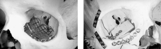
FIGURE 43.3 Use of the flag-shaped orbital floor plate (Synthes Maxillofacial, Paoli, PA) to reconstruct a large defect involving the orbital floor and medial wall and extending back to the posterior third of the orbit. (Reproduced with permission from: Hammer, B. Orbital Fractures: Diagnosis, Operative Treatment, Secondary Corrections. Hogrefe & Huber, 1995)
is the lateral orbital wall, where the zygoma forms a long articulation with the greater wing of the sphenoid.
The second most important landmark is the zygomatic arch.10 Both sites need to be exposed simultaneously to allow for exact three-dimensional positioning of the zygoma.
Reconstruction of the naso-ethmoid area (inner orbital frame) varies according to the type of injury.11 Depending on the degree of fragmentation of the canthal ligament-bearing (central) fragment, simple stabilization with plates or a transnasal canthopexy is indicated.
Reconstruction of the internal orbit is indicated in defects extending into the posterior third of the orbit and/or involving two or more orbital walls. These defects are complicated by the following facts:
•The posterior bony ledge is very small and therefore does not offer support for grafts.
•Disruption of the periorbit with fat protruding on both sides of the retractors makes exposure and visibility difficult.
Inadequate reconstruction of these defects results in serious cosmetic and functional defects, of which the secondary correction is difficult if not impossible. It is therefore of utmost importance to identify these defects in CT scans and to perform a meticulous primary repair.
The preferred material for repair is autologous bone (calvaria or iliac crest), eventually combined with a titanium plate to support the grafts. It is important to realize that these large defects cannot be reconstructed with a single graft. With the techniques presently available, it would be very difficult to exactly tailor it to the complex shape of such a defect, not to
B. Hammer
FIGURE 43.4 A cantilevered bone graft can be used to reconstruct the key area. It provides a stable basis for further bone grafts, which can be wedged in without fixation. (Reproduced with permission from: Hammer, B. Orbital Fractures: Diagnosis, Operative Treatment, Secondary Corrections. Hogrefe & Huber, 1995)
mention the difficulties of inserting such a graft into the orbit. To overcome this problem, the defect is reconstructed with several smaller grafts. The first one reconstructs the key area and serves as a platform to support the additional grafts.1 This first graft is either a specially designed mesh plate (Synthes Maxillofacial, Paoli, PA) orbital floor plate; (Figure 43.3) or a cantilevered bone graft (Figure 43.4). This rigid fixation technique for the internal orbit allows predictable three-di- mensional restoration of the orbital shape and volume. Additional bone grafts are inserted to complete the reconstruction. They usually can be wedged in without further fixation.
At completion of the reconstruction, the globe should protrude by about 2 mm to compensate for later volume loss after resolution of the swelling. The procedure is completed by a forced duction test to make sure that no periorbital tissue is entrapped between the grafts, which could cause motility problems.
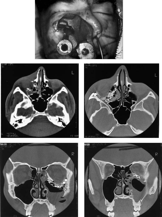
Case Example (Figure 43.5)
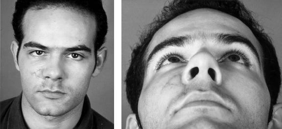
A 21-year-old man was hit in the face by an iron piece of a truck brake, causing a complex fracture of the right orbit involving the floor and the medial wall back to the apex. Inspite of the severe bony destruction, the eye was intact. Reconstruction was performed using a flag-shaped orbital plate (Synthes Maxillofacial, Paoli, PA) in combination with calvarial bone grafts. Healing was uneventful. Diplopia in downward gaze gradually resolved over a period of 9 months without any additional surgery.
43. Orbital Reconstruction |
481 |
a
b |
c |
d |
e |
FIGURE 43.5 (a) The patient on admission, with a heavy iron piece impaled in the face. (b) Axial CT scan showing complete destruction of the orbital floor. (c) Axial and (d,e) coronal CT scans show-
ing reconstruction of the right orbit with a titanium plate and calvarial bone grafts.
Continued.
482 |
|
|
|
|
|
|
|
B. Hammer |
f |
|
|
|
|
|
|
|
g |
|
|
|
|
|
|
|
|
|
|
|
|
|
|
|
|
|
|
|
|
|
|
|
|
|
|
|
|
|
|
|
|
|
|
|
|
|
|
|
|
|
|
|
|
|
FIGURE 43.5 Continued. (f,g) The patient 10 months after the accident. Normal eye position and binocular vision have been restored.
References
1.Manson PN, Glassman D, Iliff N, Vanderkolk C, Dufresne C. Rigid fixation of fractures of the internal orbit. Plast Surg Forum 1988;11:80–82.
2.Kawamoto HK. Late posttraumatic enophthalmos: a correctable deformity? Plast Reconstr Surg. 1982;69:423–430.
3.Hammer B. Orbital Fractures: Diagnosis, Operative Treatment, Secondary Corrections. Bern, Göttingen, Toronto, Seattle: Hogrefe & Huber; 1995.
4.Stutzin JM, Wagstrom L, Kawamoto H, Wolfe SA. Anatomy of the frontal branch of the facial nerve: the significance of the temporal fat pad. Plast Reconstr Surg. 1989;83:265–271.
5.SullivanWG,KawamotoHK.Periorbitalmarginotomies:anatomy and application. J Craniomaxillofac Surg. 1989;17:206–209.
6.Glassmann RD, Petty P, Vanderkolk C, Iliff N. Techniques for improved visibility and lid protection in orbital explorations.
J Craniofac Surg. 1990;1:69–71.
7.Philips JH, Gruss JS, Wells MD, Chollet A. Periosteal suspension of the lower eyelid and cheek following subciliary exposure of facial fractures. Plast Reconstr Surg. 1991;88:145– 148.
8.Manson PN, Hoope JE, Su CT. Structural pillars of the facial skeleton: an approach to the management of Le Fort fractures.
Plast Reconstr Surg. 1980;66:54–61.
9.Gruss JS, Bubak PJ, Egbert MA. Craniofacial fractures. An algorithm to optimize results. Clin Plast Surg. 1992;19:195–206.
10.Gruss JS, Van Wyck L, Philips JH, Antonyshyn O. The importance of the zygomatic arch in complex midfacial fracture repair and correction of posttraumatic orbitozygomatic deformities. Plast Reconstr Surg. 1990;85:878–890.
11.Markowitz BL, Manson PN, Sargent L, Vanderkolk CA, Yaremchuk M, Glassman D, Crawley WA. Management of the medial canthal tendon in nasoethmoid orbital fractures: the importance of the central fragment in classification and treatment. Plast Reconstr Surg. 1991;87:843–853.