

17
The ITI Dental Implant System in Maxillofacial Applications
Dieter Weingart, Daniel A. Buser, and Hans-Peter Weber
In severe trauma cases, after jaw resection in tumor surgery, and especially in cases of severe atrophy of the maxillary or mandibular alveolar ridge, a direct implant placement using the one-stage approach with ITI implants as described in Chapter 15 is often not possible. Also, the technique of guided bone regeneration discussed in that chapter would not be an efficient method to restore areas of such extended and severe alveolar atrophy. Therefore, a vertical augmentation with bone grafts most frequently obtained from the iliac crest is the method of choice in patients presenting with such conditions (Figures 17.1–17.4). As with guided bone regeneration, two methods regarding timing of implant placement may be differentiated: (1) implant insertion simultaneously with the bone grafts in which instance the implants serve to stabilize the grafts to the basal bone; and (2) stage approach, that is, the bone grafts are stabilized by means of miniplates or screws, which are removed after graft healing at which time the implants are inserted (Figures 17.1 and 17.2).
As a prerequisite for the use of free bone grafts, a maximum wound closure during the healing phase is required. Accordingly, the implants in this indication need to be inserted to the bone level, and the mucoperiosteal flap must cover the implants after suturing. A modification of the standard ITI Dental Implant System was necessary to allow that at the time of secondstage surgery (i.e., after bone-graft healing and osseointegration of the implants) transmucosal extensions can be attached. For this purpose, the ITI Extender System was developed.1–5 The available extensions allow the adaptation of the periimplant mucosa to this transmucosal component (Figure 17.5d).
After completion of soft tissue healing following secondstage surgery, any of the prosthetic abutments of the regular ITI system may be placed on top of the extensions, and the superstructure is fabricated according to standard procedures.
Surgical Procedure
As outlined earlier, the implants used for the stabilization of bone grafts are to be inserted into the transplants in a submerged manner, mainly for reasons of infection prophylaxis
and prevention of graft resorption. The ITI full-body screws, available in lengths of 6 to 16 mm, are used for these indications. Owing to their flared neck, the ITI screw implants function as tension screws, building up an interfragmentary compression between the natural bone bed of the jaw bone and the bone transplant (Figure 17.6e).
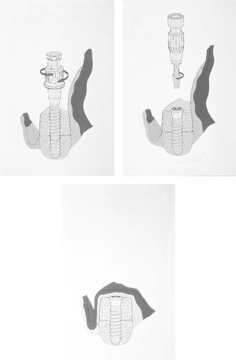
The surgical augmentation procedure and the implantation with ITI screw implants as well as the use of the transgingival extension system is documented step by step in Figures 17.5 and 17.6. At first surgery, the implant (ITI FS) is inserted to its shoulder into the bone graft and covered with a small closure screw. The mucoperiosteal flap is then positioned over the bone graft and implants (Figure 17.6g). At second-stage surgery following a healing phase of 3 to 6 months, the implants are exposed, the healing caps removed, and the basal screws and the mucosa cylinders are inserted and covered with healing caps (Figures 17.5a–d). After completion of wound healing (3 to 4 weeks), the prosthetic phase is started with the insertion of the abutments after removal of the healing caps.
Mechanical Aspects
At second-stage surgery, it is important to consider that the basal screw and the mucosa cylinder are used in corresponding pairs and in accordance with the standard lengths (Figure 17.7). The microgaps between the implant and the extension parts are kept as small as technically possible.
This transgingival unit of the extender system has been mechanically tested under different loading conditions. As a result of preliminary tests with different designs, an integrated attachment (basal screw) was chosen. As usual for ITI secondary components, its apical portion comprises an 8° cone and a 2-mm screw for attachment to the implant. This cone- to-screw design provides a frictional fit, eliminating the risk of loosening of the basal screw. The design of the coronal portions of the basal screw consists of a threaded part to which the corresponding mucosa cylinder is attached (Figure 17.7). It is preferably tightened with a torque meter adjusted to approximately 35 Ncm.
164
17. The ITI Dental Implant System in Maxillofacial Applications |
165 |
a |
b |
c |
d |
e
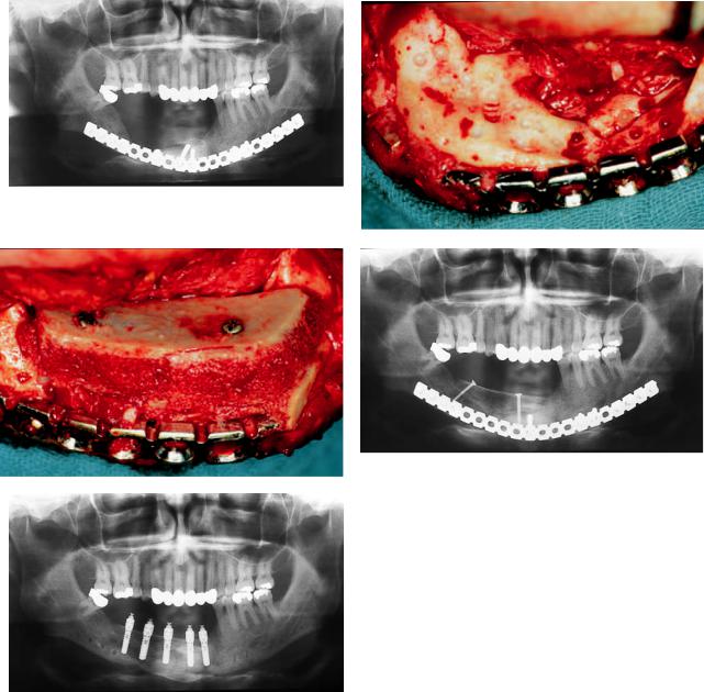
FIGURE 17.1 (a) Situation after a comminuted fracture of the mandible with a defect in the region of the right alveolar ridge stabilized with an AO 2.7 reconstruction plate. (b) The defect is exposed. The remaining vertical bone height in the premolar area is only 3 to 4 mm. (c) An autogenous corticocancellous iliac bone graft is adapted with two lag screws. (d) Radiological control 6 months after bone grafting before implant placement. (e) Situation after mandibular reconstruction and implant placement of ITI full-body screw. For transgingival elongation, the ITI Extender System is inserted.
166 |
D. Weingart, D.A. Buser, and H.-P. Weber |
a |
b |
c |
d |
e
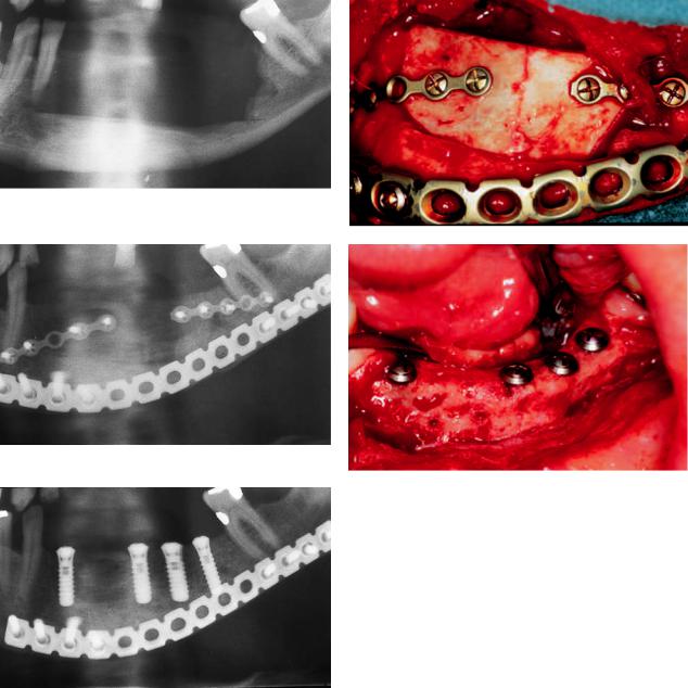
FIGURE 17.2 (a) Bone resection because of an ameloblastoma of the mandible. (b,c) After pathohistological evaluation of the resection border, reconstruction of the mandible with an autogenous corticocancellous iliac bone graft. Fixation of the graft with AO 2.0 miniplates, and stabilization of the mandible with an AO 2.4 universal plate. The alveolar nerve was preserved and lateralized. (d,e) The ITI full-body screw implants are inserted 5 to 6 months after bone grafting.

a |
b |
c |
d |
e |
|
|
|
|
|
|
|
f |
|
|
|
|
|
|
|
|
|
|
|
|
|
|
|
|
|
|
|
|
|
|
|
|
|
|
|
|
|
|
|
|
|
|
|
|
|
|
|
|
|
|
|
|
|
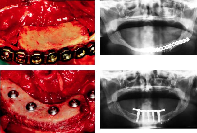
FIGURE 17.3 (a) Situation after resection in the left mandible because of a carcinoma of the floor of the mouth. (b) Restoration by microsurgically revascularized iliac crest bone graft. (c) The implants are inserted into the bone graft during a second-stage approach. (d) Good osseointegration of the implants in the grafted bone with only minimal vertical resorption. The ITI Extender System was inserted 3
months following implant placement. (e) Preoperative extraoral aspect of the patient, with perforation of the reconstruction plate through the skin. (f) Postoperative extraoral aspect of the patient following mandibular reconstruction with revascularized iliac bone graft and implant placement.
168 |
D. Weingart, D.A. Buser, and H.-P. Weber |
a |
b |
c |
d |
FIGURE 17.4 (a) Extreme atrophy of the mandibular alveolar ridge. Measurements for evaluating the vertical height were performed. Patient refused an augmentation procedure. (b) Situation 2 years later. Increase of alveolar ridge atrophy. Patient came back with a fracture of the extremely atrophied left mandible. (c) Intraoperative sit-
uation after an extraoral approach: Fracture and dislocation occurred because there was no bone in the middle of the mandibular ridge.
(d) Initial stabilization of fracture with miniplate fixation to allow anatomic segment positioning for reconstruction plate application in the same operation.
17. The ITI Dental Implant System in Maxillofacial Applications |
169 |
e |
f |
g |
h |
FIGURE 17.4 Continued. (e) Stabilization of the fracture with an AO 2.4 reconstruction plate and simultaneous bone grafting with autogenous iliac bone. (f) Radiological control 6 months after fracture treatment and augmentation on the left side of the mandible. (g) Augmentation on the anterior and right region of the mandible: the implants are inserted through the corticocancellous bone graft into the mandible (see Figure 17.6). Good interfragmentary compression be-
tween the natural bone bed of the jaw bone and the bone transplant due to implant configuration and a certain lag-screw effect. (h) Situation after posthodontic treatment with a bar suprastructure: the ITI Extender System in place. Compare the bony situation with (b). Increase in vertical bone height and titanium microplate for fracture adaption still in place.

170 |
D. Weingart, D.A. Buser, and H.-P. Weber |
a |
b |
c |
d |
FIGURE 17.5 (a) After the healing phase, the implants are exposed either by incision or by punching. The basal screw (b) and the mucosa cylinder (c) are inserted with a special insertion instrument. (d) The assembled transgingival elongation system.
17. The ITI Dental Implant System in Maxillofacial Applications |
171 |
a |
b |
c |
d |
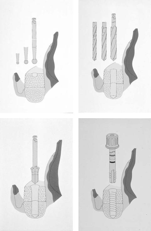
FIGURE 17.6 Step-by-step representation of the surgical sequence. After vestibular incision and adoption of the transplant, the implant bed is prepared in the usual way. (a) Marking with the round bur.
(b) Drilling to the desired depth with three spiral drills. (c) Profiling of the neck portion. (d) The next step is to pretap the thread in accordance with the depth.
Continued.
172 |
D. Weingart, D.A. Buser, and H.-P. Weber |
e |
f |
g
FIGURE 17.6 Continued. (e) The implant is introduced with a standard insertion instrument through the bone graft into the ridge. (f) Insertion of the closure screw into the subgingival positioned implant. (g) The situation after suturing the periosteum and the mucosa.
17. The ITI Dental Implant System in Maxillofacial Applications |
173 |
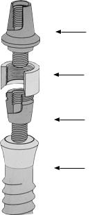
Abutment
Mucosa Cylinder
Basal Screw
Implant
FIGURE 17.7 Parts of the ITI Extender System.
With regard to their coronal configuration, the prosthetic components of the extender system correspond to those of the standard ITI Dental Implant System (conical abutment, retentive anchor, and octa-abutment) and are also manufactured from pure titanium. Any of these abutments can be attached to the mucosa cylinder.
Maximum tightening moments of more than 400 Ncm could be achieved with the new transgingival unit compared with 125 Ncm observed with a conventional 2-mm flat coupling screw. Additional dynamic loading tests proved that the loosening moment remained approximately 10% above the tightening moment after 2,000,000 cycles.4
Summary
Positive experience and results with endosteal implants in the field of standard oral implantology led to an extension of the indication to implantations into transplants. In these cases, the simultaneous use of screw implants facilitated optimal graft adaptation and fixation. Originally, ITI implants were designed for a transmucosal (one-stage) implant placement. Using bone-graft procedures, it is necessary to cover the bone graft with a soft tissue flap to get satisfactory incorporation
of the bone. These cases need second-stage surgery and a special abutment device.
Theextendersystempresentedhereprovidesasimplemethod of restoring ITI implants placed in combination with autogenous bone transplants with various prosthetic superstructures.
References
1.Asikainen P, Sutter F. The new distance system for the submergible use of the ITI-Bonefit Implants. J Oral Implantol. 1990;4:48–54.
2.Sutter F, Weingart D, Mundwiler U, Sutter F, Asikainen P. ITI implants in combination with bone grafts: design and biomechanical aspects. Clin Oral Implants Res. 1990;5:164–172.
3.Weingart D, Strub JR, Schilli W. Kieferchirurgisch-prothetisches Konzept zur implantologischen Versorgung bei unterschiedlichem Atrophiegrad des zahnlosen Patienten. Z Stomatol. 1992;3:137–145.
4.Sutter F, Weber HP, Sorensen J, Belser U. The new restorative concept of the ITI Dental Implant System: design and engineering. Int J Periodont Rest Dent. 1993;13:409–431.
5.Weingart D, Strub JR, Schilli W, Schenk R, Kleinheinz J, Hürzeler B. Mandibular ridge augmentation combining onlay iliac bone graft with endosseous implant placement in dogs. J Dent Res. 1993;72:204–205.