

- •Preface
- •Acknowledgments
- •Contents
- •Contributors
- •1. Introduction
- •2. Evaluation of the Craniomaxillofacial Deformity Patient
- •3. Craniofacial Deformities: Review of Etiologies, Distribution, and Their Classification
- •4. Etiology of Skeletal Malocclusion
- •5. Etiology, Distribution, and Classification of Craniomaxillofacial Deformities: Traumatic Defects
- •6. Etiology, Distribution, and Classification of Craniomaxillofacial Deformities: Review of Nasal Deformities
- •7. Review of Benign Tumors of the Maxillofacial Region and Considerations for Bone Invasion
- •8. Oral Malignancies: Etiology, Distribution, and Basic Treatment Considerations
- •9. Craniomaxillofacial Bone Infections: Etiologies, Distributions, and Associated Defects
- •11. Craniomaxillofacial Bone Healing, Biomechanics, and Rigid Internal Fixation
- •12. Metal for Craniomaxillofacial Internal Fixation Implants and Its Physiological Implications
- •13. Bioresorbable Materials for Bone Fixation: Review of Biological Concepts and Mechanical Aspects
- •14. Advanced Bone Healing Concepts in Craniomaxillofacial Reconstructive and Corrective Bone Surgery
- •15. The ITI Dental Implant System
- •16. Localized Ridge Augmentation Using Guided Bone Regeneration in Deficient Implant Sites
- •17. The ITI Dental Implant System in Maxillofacial Applications
- •18. Maxillary Sinus Grafting and Osseointegration Surgery
- •19. Computerized Tomography and Its Use for Craniomaxillofacial Dental Implantology
- •20B. Atlas of Cases
- •21A. Prosthodontic Considerations in Dental Implant Restoration
- •21B. Overdenture Case Reports
- •22. AO/ASIF Mandibular Hardware
- •23. Aesthetic Considerations in Reconstructive and Corrective Craniomaxillofacial Bone Surgery
- •24. Considerations for Reconstruction of the Head and Neck Oncologic Patient
- •25. Autogenous Bone Grafts in Maxillofacial Reconstruction
- •26. Current Practice and Future Trends in Craniomaxillofacial Reconstructive and Corrective Microvascular Bone Surgery
- •27. Considerations in the Fixation of Bone Grafts for the Reconstruction of Mandibular Continuity Defects
- •28. Indications and Technical Considerations of Different Fibula Grafts
- •29. Soft Tissue Flaps for Coverage of Craniomaxillofacial Osseous Continuity Defects with or Without Bone Graft and Rigid Fixation
- •30. Mandibular Condyle Reconstruction with Free Costochondral Grafting
- •31. Microsurgical Reconstruction of Large Defects of the Maxilla, Midface, and Cranial Base
- •32. Condylar Prosthesis for the Replacement of the Mandibular Condyle
- •33. Problems Related to Mandibular Condylar Prosthesis
- •34. Reconstruction of Defects of the Mandibular Angle
- •35. Mandibular Body Reconstruction
- •36. Marginal Mandibulectomy
- •37. Reconstruction of Extensive Anterior Defects of the Mandible
- •38. Radiation Therapy and Considerations for Internal Fixation Devices
- •39. Management of Posttraumatic Osteomyelitis of the Mandible
- •40. Bilateral Maxillary Defects: THORP Plate Reconstruction with Removable Prosthesis
- •41. AO/ASIF Craniofacial Fixation System Hardware
- •43. Orbital Reconstruction
- •44. Nasal Reconstruction Using Bone Grafts and Rigid Internal Fixation
- •46. Orthognathic Examination
- •47. Considerations in Planning for Bimaxillary Surgery and the Implications of Rigid Internal Fixation
- •48. Reconstruction of Cleft Lip and Palate Osseous Defects and Deformities
- •49. Maxillary Osteotomies and Considerations for Rigid Internal Fixation
- •50. Mandibular Osteotomies and Considerations for Rigid Internal Fixation
- •51. Genioplasty Techniques and Considerations for Rigid Internal Fixation
- •52. Long-Term Stability of Maxillary and Mandibular Osteotomies with Rigid Internal Fixation
- •53. Le Fort II and Le Fort III Osteotomies for Midface Reconstruction and Considerations for Internal Fixation
- •54. Craniofacial Deformities: Introduction and Principles of Management
- •55. The Effects of Plate and Screw Fixation on the Growing Craniofacial Skeleton
- •56. Calvarial Bone Graft Harvesting Techniques: Considerations for Their Use with Rigid Fixation Techniques in the Craniomaxillofacial Region
- •57. Crouzon Syndrome: Basic Dysmorphology and Staging of Reconstruction
- •58. Hemifacial Microsomia
- •59. Orbital Hypertelorism: Surgical Management
- •60. Surgical Correction of the Apert Craniofacial Deformities
- •Index
47
Considerations in Planning for Bimaxillary Surgery and the Implications of Rigid Internal Fixation
Brian Alpert, George M. Kushner, and Gerald D. Verdi
Rigid fixation is one of the latest and indeed one of the most significant advances in the surgery of dentofacial deformities. Although the use of intermaxillary fixation is routine to the surgeons who utilize it, it is often a cause of anxiety to others. Orthodontists, nurses, anesthesiologists, and other health care providers often have great concern, indeed fear, about its use, as do many patients for whom the prospect of being “wired shut” often negatively impacts on their decision to undergo corrective surgery.
The advantages of rigid fixation are obviously an easier and shorter hospital admission, with the elimination of the need for overnight intubation or nasal airways, which are often associated with intensive care unit or transitional care unit stays. The avoidance of intermaxillary fixation has dramatically diminished the perception of, if not the actual existence of, potential airway problems.
Rigid fixation permits an earlier return to function with regard to mastication and speech, which otherwise would be limited during the convalescent period. There is decreased long-term trismus, and by the time a patient who is treated with intermaxillary fixation is allowed to open, a comparable patient with rigid internal fixation is at full function.
Several studies have shown rigid fixation to be at least as stable as conventional skeletal fixation,1–3 with others indicating that it is more stable.4,5 There has been a resurgence of attempts to do corrections with rigid fixation that in the past were deemed inherently unstable when wire fixation6 was utilized. These procedures include maxillary downgrafts as well as closure of open bites at the expense of the mandibular angle. It remains to be seen whether rigid fixation will offer a solution in unstable corrections.
Rigid fixation has certain disadvantages because it is a more difficult procedure and is certainly more technique sensitive, with very little margin for error. Utilizing conventional techniques with wire gives a certain amount of leeway, as adjustments can be made during the convalescent period. The segments themselves will exhibit a degree of movement to offer this potential adjustment, as opposed to the use of rigid fixation in which the segments are absolutely stable with only orthodontic adjustments possible.
The learning curve in the use of rigid fixation is much longer than wire fixation techniques. As experience is gained, however, surgeons can often apply rigid fixation more rapidly than conventional wiring techniques. There is certainly also greater potential for morbidity with rigid fixation. The obvious surgical misadventure of violating a nerve or tooth root with a screw occasionally occurs. The less obvious rigidly fixed error, resulting in malposition of bone fragments, also occasionally occurs with resultant malocclusion, condylar malposition, and contour defects.
One of the major reasons for increased morbidity potential with rigid internal fixation is when it is necessary to perform bilateral sagittal split ramus osteotomies for the correction of mandibular deformities. This particular procedure for the correction of mandibular prognathism has greater inherent potential for morbidity than the oblique subcondylar osteotomy, (which does not readily lend itself to rigid fixation techniques).
Rigid fixation is more costly because specialized equipment and costly hardware are required. However, this increased equipment expense is usually offset by a shorter, less costly hospital stay.
Indications for Bimaxillary Surgery
A discussion of all the intricacies of planning for dentofacial deformity correction is beyond the scope of this review. However, there are a number of indications for two-jaw surgery. Large anteroposterior discrepancies often necessitate two-jaw surgery. The treatment of at least moderate mandibular excess or deficiency in conjunction with open-bite, long or short face deformity almost always requires simultaneous mobilization of both jaws. When significant asymmetries exist in both maxillary and mandibular midlines, two-jaw surgery is often necessary. When discrepancies are present in the orientation of the occlusal plane either in the anteroposterior dimension as in deep bite deformities, or in lateral dimension as in hemifacial microsomia or condylar hyperplasia cases, simultaneous mobilization of both jaws is performed.
Obviously, one can usually find an indication to operate
47. Bimaxillary Surgery and Rigid Internal Fixation
both jaws. However in the context of a whole face, a 2- to 3- mm correction is insignificant. As such, a two-jaw correction for 4 to 6 mm of total discrepancy in the absence of midline alterations, open bites, or significant discrepancies of the occlusal plane is a great deal of treatment for minimal gain. The surgeon must consider the potential for morbidity with respect to the benefit gained.
There are some basic truths with respect to orthognathic surgery. It is well known that the conventional Le Fort I maxillary osteotomy (downfracture) has minimal potential for long-term morbidity. This differs from the sagittal split ramus osteotomy, which has significant potential for permanent morbidity in the form of paresthesia and regression or relapse. Condylar resorption, TMJ problems, etc. are more unusual complications of this operation. Similarly, segmental osteotomies are not periodontally predictable; 20% of these procedures demonstrate permanent periodontal defects at the osteotomy site. The Le Fort II osteotomy has also been found to be a relatively unstable correction.
Recognition of these “truths” should guide the surgeon and orthodontist in developing a treatment plan that should fit the operation to the patient and not the patient to the operation. The development of a treatment plan is based on establishing a diagnosis from which a list of the patient’s problems and the available surgical or orthodontic solutions is formulated. Discussion between the surgeon, orthodontist, and the patient should weigh the potential for morbidity of the solutions to arrive at a treatment plan with a favorable risk-to-benefit ratio. Fundamentally, the benefit gained must outweigh the risk of complications, because minor problems will require minor corrections, while major problems will require major corrections. (One does not need a sledgehammer to drive a tack.) Consideration must also be made of other treatment alternatives, all of which could be valid options. A patient with a dentofacial deformity could be presented to five different surgical-orthodontic teams and get multiple alternative treatment plans, all of which may be acceptable. Beauty and facial form are in the eyes of the beholder.
There are numerous factors to be considered in the development of a surgical treatment plan that will guide the surgeon and the orthodontist. These include nasal form, nasolabial angle, lip to incisal edge relationship, neck drape, facial height and proportion, and dental and skeletal midlines. Nasal form is often a determinant for which the jaw needs to be corrected. For example, if a patient has a large although well-formed nose and an absolute mandibular prognathism, mandibular setback will make the nose seem even larger, and a maxillary advancement may be indicated. Maxillary advancement in an individual with a small nose may create an anthropoid appearance. The nasolabial angle offers a point of reference with regard to maxillary advancement or setback. A setback in an obtuse nasolabial angle will make it even more obtuse. Maxillary advancement with an obtuse nasolabial angle will make it more acute.
Lip to incisal edge is one of the more critical areas of assessment and is a reference for the vertical position of the maxilla. The patient should show 2 to 4 mm of tooth at rest.
523
Neck drape is critically important in determining mandibular corrections. One needs to be careful in setting back a mandible and creating jowls. Indeed, many patients with true, but moderate mandibular prognathisms are better treated by advancing their maxilla because their neck drape is already optimal. Facial height and proportion need to be assessed along with dental and skeletal midlines. All these considerations must be discussed with the patient and family before surgery so they can participate in the treatment planning.
What Is Needed from the Orthodontist
Once a surgical decision has been made, the orthodontist is responsible for decompensating the dentition. Fundamentally, this means placing the teeth in their optimal position to basal bone. Often the deformity that has dental compensations will become more skeletally apparent following orthodontic treatment. Indeed, changes in the surgical treatment plan often become evident at this point in orthodontic preparation. In any event, the orthodontist needs to decompensate the dentition so that models fit into an appropriate postoperative relationship. Obviously, in a suitably orthodontically decompensated dentition, nonsurgical attempts to close an anterior open bite must be avoided. The orthodontic appliances will also need appropriate surgical hooks for intraoperative intermaxillary fixation and/or postoperative training elastics. At this stage, the surgeon and orthodontist (and patient!) should decide on an optimal lip to incisal edge relationship.
Setting Up the Case
In our view, anatomic articulators and facebow transfers add an aura of precision and mystique to planning and splint fabrication but are unnecessary for precise surgical execution. One needs dental models that can be articulated in both the final occlusal relationship and a preoperative occlusal relationship. The relationship of the teeth (which can be seen and of which we have an exact facsimile) are used to set the case, not areas for osteotomies and ostectomies that can only be imagined.
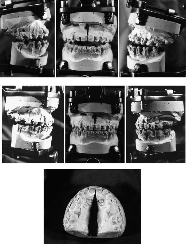
In bimaxillary osteotomies, either jaw can be mobilized first, but it is preferable to mobilize the maxilla first because it can almost always be rigidly fixed. If a mandibular sagittal split is unfavorable, it may not be possible to perform rigid fixation in a convenient manner. If this occurs, then the ability to relate the maxilla to the mandible is lost. In the technique to be described, a transitional interocclusal splint is used to relate the maxilla in the corrected position to the unoperated mandible. Then a final splint will relate the mandible in the desired position to the corrected (and rigidly fixed) maxilla. The models are articulated and marked in the postoperative position as well as the preoperative position with appropriate vertical and horizontal references lines (Figure 47.1). An interocclusal splint is made relating the models in the final occlusion (Figure 47.2).
524 |
B. Alpert, G.M. Kushner, and G.D. Verdi |
a
b
c
FIGURE 47.1 (a) Models articulated in presurgical relationship. Reference lines are marked. (b) Models articulated in final postsurgical relationship. (c) Note midpalatal split and widening of maxilla are required in this instance.
47. Bimaxillary Surgery and Rigid Internal Fixation |
525 |
a
b
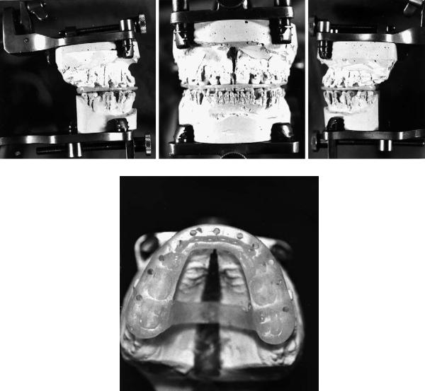
FIGURE 47.2 (a) A final interocclusal splint (index) is made in the postsurgical relationship. (b) Note the palatal strap on the index, which minimizes distortion or bending of the index and supports the
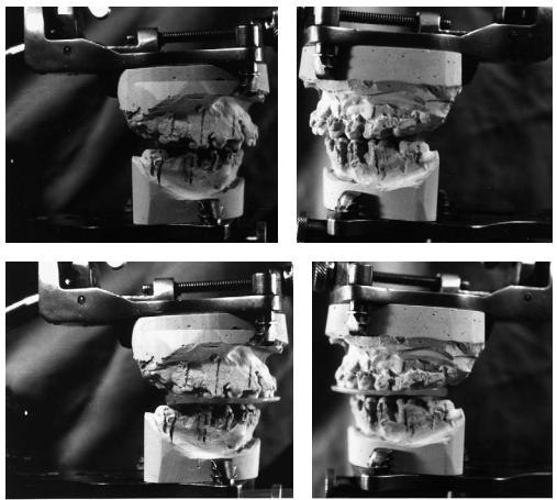
The maxillary model in corrected position is now related to the mandibular model in its uncorrected position utilizing the horizontal and vertical reference lines on the teeth as a guide (Figures 47.3a,b). A “transitional” interocclusal splint (index) is made at this point (Figures 47.3c,d). If the maxilla has been segmented, a splint within a “final’ splint can be used (Figures 47.4a–c). This allows only one splint to be wired into place (making the segmented maxilla intact) rather than changing splints after the maxilla is rigidly fixed. Thus, only one splint
expansion of the maxilla during convalescence because maxillomandibular fixation is not used.
will have to be wired (fixed) to the maxillary arch after it is segmented. The transitional splint carries with it all the anteroposterior (AP), lateral, and occlusal plane corrections that the treatment plan calls for, using the maxillary and mandibular teeth as reference points and the patient’s mandible as the articulator. The vertical position (lip to incisal edge relationship) is set at surgery. Thus, an extremely precise treatment plan that utilizes fixed reference points, the teeth, can be incorporated into two interocclusal acrylic splints (indices) (Figure 47.4).
526
Additional Treatment Planning
Considerations
Multiple Segment Le Fort I
As surgical experience has been gained and orthodontics has advanced, we tend to do fewer multiple segment Le Fort I osteotomies. In our institution, we try to achieve single piece Le Fort I osteotomy preparation by having the orthodontist “work harder.” An exception is midline or paramidline splits for posterior expansion. In excessive posterior maxillary or transverse hyperplasia, it is not unusual to set the case up with good cus- pid-to-cuspid occlusion, but an open bite posteriorly. These posterior open bites close spontaneously, avoiding the need for multiple segment osteotomies.
Cleft Palate Patients
Rather than perform Le Fort I osteotomies with simultaneous closure of fistulae and bone grafting on extensive clefts utilizing anterior soft tissue pedicles (which can pose consider-
a
c
B. Alpert, G.M. Kushner, and G.D. Verdi
able difficulties), we now simultaneously graft the alveolar clefts and close the fistulae in advance (age 7 to 12). In this way, we can perform a conventional Le Fort I osteotomy on a oneor two-piece maxilla without the anterior pedicles and surgical struggle (with the attendant increased risk of necrosis of flaps and recurrent fistulae).
Setting Facial Height (Lip to Incisal Edge)
Setting proper facial height has been one of the most controversial areas in orthognathic surgery planning. A number of techniques have been advocated for this endeavor. Some have used measured bone removal with internal reference points based on cephalometric prediction. Others have used calipers from the nasion to the incisal edge of the maxillary central incisor.7,8 Yet others have measured from a screw placed in the nasion to the incisal edge of the central incisor.9 We utilize the relationship of the inferior margin of the lip to the incisal edge. The salient point of this technique is that the nose must be undistorted by the endotracheal tube so that the lip is not retracted or elongated. (See Figures 47.6a,b later in this chapter.)
b
d
FIGURE 47.3 (a–d) Utilizing the reference lines as a guide, the maxillary model in corrected position is related to the uncorrected mandibular model. Note that the maxilla has been advanced and the open bite corrected at the expense of the posterior maxilla.
47. Bimaxillary Surgery and Rigid Internal Fixation |
527 |
a
b |
|
c |
|
|
|
FIGURE 47.4 (a–c). The final splint and transitional splint serve as blueprints for transferring the extremely precise treatment plan from the laboratory to surgery. (c) Note the final splint is right and the transitional splint is left. The final splint is reinforced with a palatal strut.
Setting Condylar Position (Bilateral Sagittal Split
Ramus Osteotomy [BSSRO])
The available techniques utilized have been high-low wires,10,11 various mechanical devices that relate the proximal segment to the maxilla (bone to bone),12,13 the proximal segment to the maxillary arch wire,14 the maxillary arch wire to reference points on proximal segments,15,16 etc. Other techniques have advocated the use of bone clamps, while others utilize screw slots.17 Our technique uses manual repositioning with a trocar point, which is described later.
segment while avoiding tooth roots (Figure 47.5). Bone should be judiciously trimmed in the maxillary buttress and piriform aperture areas so that contact remains in these areas
Considerations for Rigid Fixation
In maxillary surgery, the surgeon must think of rigid internal fixation when designing the osteotomy. The superior regions of the piriform apertures and zygomatic buttresses need be exposed to find substantial bone that will hold screws. Likewise, the osteotomy should be designed a little higher than normal to allow placement of the plates on the mobilized
FIGURE 47.5 Ideal lines of Le Fort I osteotomy when the use of rigid fixation is intended. This may be considered somewhat higher than normal to facilitate plate and screw fixation.

528
a
b
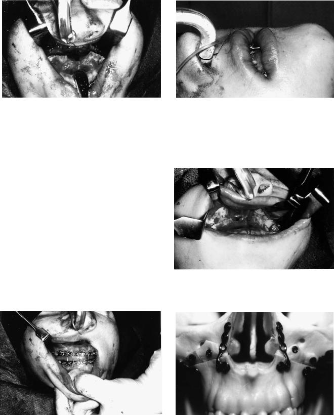
FIGURE 47.6 (a) The endotracheal tube is placed and positioned so that the nose is undistorted, and can be returned to this undistorted position during surgery. (b) Note how the tube is fixed with a heavy suture to the nasal septum.
where rigid fixation is to be placed. The hardware should maintain bone contact in the piriform aperture and buttress regions rather than holding the fragments apart.
Precise, stable intermaxillary fixation cannot be overemphasized to avoid slipping of the occlusion during screw tightening. Position screws should be utilized instead of lag screws to minimize condylar distraction caused by rotation of the segments. The screws should be inserted perpendicular to the bone to avoid sliding the fragments when tightening the screws. In splits that involve rotation of the mandible around the horizontal axis, bone between the splits needs to be trimmed or shims utilized before placement of screws in these
B. Alpert, G.M. Kushner, and G.D. Verdi
areas of rotation to permit passive fit of segments. Finally, impacted teeth need to be removed in advance (3–6 months if possible) to permit superior quality and quantity of bone for screw fixation.
Executing the Treatment Plan During the
Surgical Exercise
The precise treatment plan has been prepared and is transferred to the patient at surgery through the use of the surgical splints. These are the presurgically determined templates or road maps that guide the surgeon during the course of the operation. One does not plan at surgery but before.
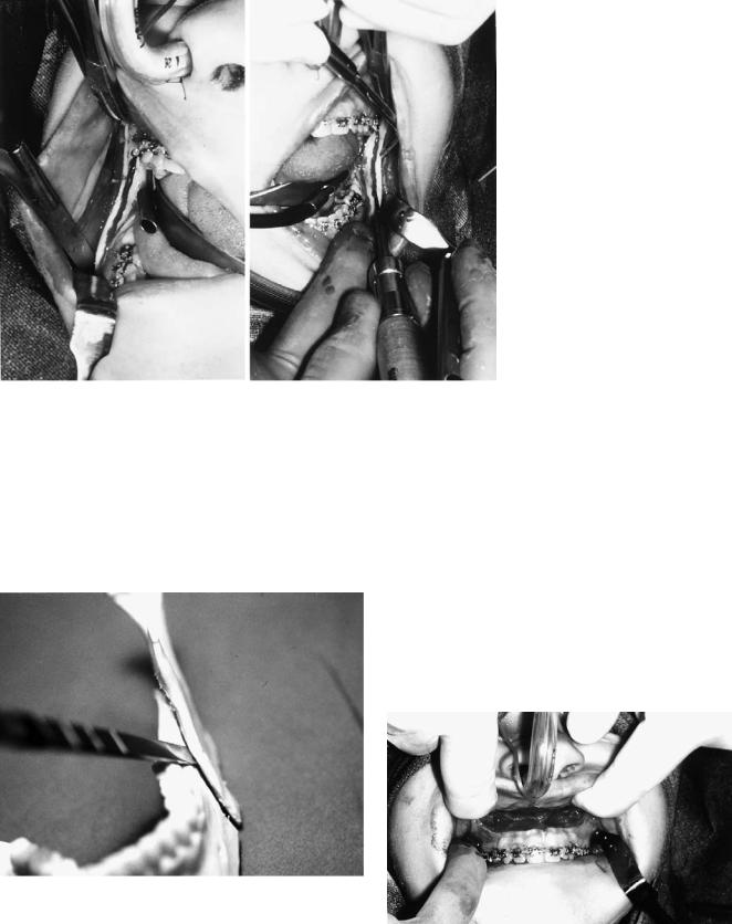
The first step in the procedure is placement and fixation of the nasoendotracheal tube (Figure 47.6a). This is critical in that the nose must be undistorted by the tube (or able to be repeatedly placed in an undistorted posture) during the course of surgery. This is the key to properly setting facial height. The tube is placed and taped securely to the head so that the nose is undistorted. Tape is not used to fix the tube to the nose. Occasionally the tube may be sewn to the nasal septum for additional security (Figure 47.6b). The position and the reproducibility of this position are checked before draping.
Following the usual prep, drape, throat pack, etc., the areas of surgery are infiltrated with local anesthetic solution for hemostasis (Figure 47.7). Use of 0.5% or 1% lidocaine with epinephrine 1:200,000 is preferred. To reduce hemorrhage during the course of surgery, the anesthesiologist is asked to keep the systolic blood pressure below 100 mmHg. This is usually done with deep inhalation anesthesia, although occasionally formal hypotensive anesthesia is utilized.
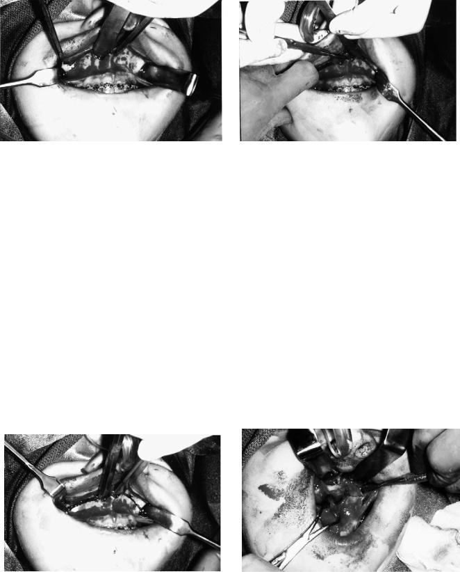
Attention is first directed to the mandible where, following exposure, cortical osteotomies are made in standard fashion (Figure 47.8). Burs are utilized although some operators prefer saws. The osteotomies are designed for “chisel access,” which later allows the chisel to be directed at the inner aspect of the buccal cortex, attempting to avoid the inferior alveolar
FIGURE 47.7 Infiltration of the incision sites with local anesthesia for hemostasis; 0.5% lidocaine with epinephrine 1:200,000 is preferred.
47. Bimaxillary Surgery and Rigid Internal Fixation |
529 |
neurovascular bundle during the split (Figure 47.9). The cuts are made bilaterally but the splits are not completed, and then the wounds are packed if necessary and attention directed to the maxilla.
A flattened U-shaped incision is made high in the vestibule from approximately second premolar to second premolar (Figure 47.10). This U-shaped incision is utilized because it al-
FIGURE 47.8 The mandibular osteotomy sites are exposed and the cortical osteotomy cuts made. The osteotomies are not yet mobilized with osteotomes.
lows for a broader buccal mucosal pedicle with ample surgical access and is less likely to tear when retractors are placed in the pterygomaxillary fissure (Figure 47.11). The piriform apertures are exposed to the infraorbital rims and the dissection is carried high on the zygomatic buttress. The nasal mucosa is stripped from the medial and lateral nasal walls and the floor.
FIGURE 47.9 Model demonstrating the concept of separating the buccal cortex of the proximal fragment from the medullary bone of the distal fragment in an attempt to avoid the neurovascular bundle. This plan necessitates “chisel access,” which means designing and contouring the cortical cuts to allow the osteotome to be directed laterally.
FIGURE 47.10 High, U-shaped incision enhances the buccal pedicle. It also is less likely to tear from retractors.
530
FIGURE 47.11 Excellent exposure of osteotomy site provided by high, U-shaped incision.
The bone cut, with bur or saw, is made from pterygomaxillary fissure to piriform aperture approximately 6 to 8 mm above the apices of the teeth (Figure 47.12). No attempt is made to remove a measured segment of bone. The nasal septum is freed with a specialized osteotome and the lateral nasal walls are sectioned with an osteotome (Figure 47.13). No attempt is made to avoid the greater palatine vessels. Pterygoid osteotomes complete the section in standard fashion.
The maxilla is downfractured with digital pressure, the use of disimpaction forceps rarely being necessary. The maxilla is now thoroughly mobilized so that it can be moved with ease to literally any position. If necessary, hemostasis is achieved with packing and/or electrocautery. With good hypotensive anesthesia, excessive bleeding is unusual. A heavy towel clip is now placed in the nasal spine region and the maxilla is mobilized anteriorly and inferiorly (Figure 47.14).
B. Alpert, G.M. Kushner, and G.D. Verdi
FIGURE 47.13 The lateral nasal walls and septum are sectioned with an osteotome. No attempt is made to preserve or avoid the greater palatine vessels.
Bone is now removed in the posterior regions of the maxilla utilizing a rongeur and large bone bur. This maneuver is accomplished at this time because these are the areas that are difficult to access once intermaxillary fixation is in place and the maxilla and the mandible are being autorotated. Significant bone reduction is accomplished in the posterior maxillary wall, the lateral nasal walls, and the region of pterygomaxillary junction. The nasal crest is removed along its entire length and replaced by a groove (Figure 47.15). At this point the maxilla is sectioned if necessary utilizing conventional technique.
The transitional splint is now fixed to the maxillary arch: if the maxilla has been sectioned, the final splint is wired to place, uniting the segments. This is followed by placement of the transitional splint within the splint. Intermaxillary fixation is now placed in this corrected position, which relates the op-
FIGURE 47.12 Buccal bone cuts are made from the pterygomaxillary fissure to piriform apertures. No attempt is made to remove a measured amount of bone; a cut is just made.
FIGURE 47.14 The maxilla is thoroughly mobilized and pulled forward with a towel clip (through the nasal spine area) for access to the posterior regions.
47. Bimaxillary Surgery and Rigid Internal Fixation
FIGURE 47.15 Bone has been reduced in the posterior maxillary and lateral nasal walls. The piriform aperture has been widened, the nasal crest eliminated, and a midline groove placed.
erated maxilla to the unoperated mandible (Figure 47.16). The maxilla and mandible are now autorotated making sure that the mandibular condyles are properly seated. The inferior margin of the upper lip to the incisal edge relationship is utilized to set facial height (Figure 47.17). It is critical that the nose (and lip) is undistorted and is in the reproducible position. At this point the only areas of bone contact remaining are between the zygomatic buttresses and piriform apertures. These are trimmed under direct vision until a proper lip to incisal edge relationship is obtained. At this point there should be bone contact in the piriform aperture and buttress regions (Figure 47.18). If proper facial height has been achieved and there is no contact at any point, shims of bone graft need be placed (Figure 47.19).
The piriform apertures are now contoured with rotary instrumentation for proper nasal form. If the maxilla is being advanced or intruded, this generally means widening and deepening these piriform apertures so that the nose is undis-
531
FIGURE 47.17 With the nose maintained in undistorted position, facial height is set using the inferior margin of the upper lip to the maxillary incisal edge. Bone is judiciously reduced from the maxillary buttress to piriform aperture until proper height is achieved. This lip-to-incisor relationship will be maintained after healing is complete.
FIGURE 47.18 Bone contact resulting from judicious trimming to achieve proper facial height.
FIGURE 47.16 Utilizing a final splint with a transitional splint, intermaxillary fixation is placed, relating the mobilized maxilla to the intact mandible.
FIGURE 47.19 Model demonstrating placement and lag screw fixation of bone grafts to establish bony continuity of anterior maxillary walls in “downgrafts.”
532 |
B. Alpert, G.M. Kushner, and G.D. Verdi |
torted in the alar regions. If this maneuver is done properly, nasal cinch sutures are unnecessary. Indeed, if the bone contour is not proper, the nasal cinch sutures are not helpful. At this point a submucous resection of the septum is performed from below if necessary to avoid buckling the septum. Care must be taken to leave adequate dorsal and caudal supports.
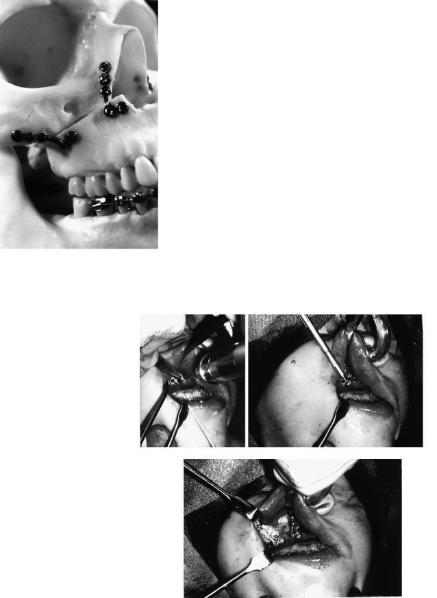
The maxilla is now fixed in this position with four plates placed bilaterally in the piriform aperture and zygomatic buttress regions. The plates are placed in sites that allow for the greatest screw retention (Figure 47.20). Anteriorly, this would be the lateral margin of the nose where the lateral nasal and anterior maxilla walls join. Posteriorly, one should extend to the buttress of the zygoma. If the bone is thin one needs to extend higher. The plates are contoured so that they rest on the bone passively. Screw holes should be placed with lowspeed twist drills of appropriate size utilizing drill guides (Figures 47.21a–c). High-speed drills without drill guides tend to whip slightly, making larger holes. Once the maxilla has been fixed in its corrected position, the intermaxillary fixation is released and the occlusion is checked (against the transitional splint). If it is not correct, the plates are removed and the fixation repeated. When the position is proper, intermaxillary
FIGURE 47.20 Model demonstrating proper placement of plate and screw fixation. Note that the double cortex on the lateral margin of the nasal bones is used anteriorly and the relatively thick zygomatic buttress posteriorly for screw fixation.
a |
b |
c
FIGURE 47.21 (a) A drill guide and low-speed twist drill are used to make holes. The drill guide centers the hole and does not allow the drill tip to “whip” and enlarge the hole. (b) Screws of appropriate length (generally 4–6 mm) fix the plate to the bone. (c) Complete fixation at piriform aperture and maxillary buttress.
47. Bimaxillary Surgery and Rigid Internal Fixation
FIGURE 47.22 Intermaxillary fixation has been released and the transitional splint discarded. The maxilla is now in proper postoperative position. Note the lateral open bite in this example, resulting from the correction of a tilted occlusal plane.
fixation is released and the transitional splint discarded (Figure 47.22).
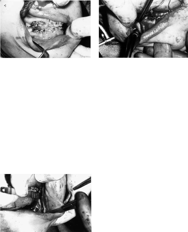
Attention is now directed to the mandible where the sagittal cuts are now completed and segments mobilized. Care is taken to direct the chisel to the outer cortical plate in an attempt to avoid the inferior alveolar neurovascular triad (Figure 47.23). Once the splits are complete, necessary detachments of pterygoid muscle on the distal fragments are done with a gloved finger. Tight intermaxillary fixation is placed utilizing the final splint as a guide. One has to ensure that the intermaxillary fixation is quite stable because tightening screws can often alter an occlusal relationship that is not rigidly fixed. Bone in and around the osteotomy sites is now contoured, trimmed, or shimmed so that it comes passively together in a position amenable to osteosynthesis.
FIGURE 47.23 Splitting of the sagittal osteotomies. Note how the osteotome is directed toward the inner aspect of the lateral cortex to avoid the inferior alveolar neurovascular bundle.
533
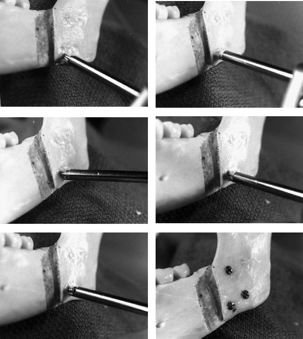
FIGURE 47.24 Use of the transbuccal trocar to place screw fixation of the sagittal osteotomies.
A transbuccal trocar is used to place the screw fixation perpendicular to the osteotomies (Figure 47.24). The point of the trocar is also utilized to control the position of the proximal fragments while screw fixation is being accomplished (Figures 47.25a–f). A 5-mm stab incision is made approximately one finger breadth inferior to the mandible below the osteotomy site. An obturator is placed into the trocar and the trocar is passed through the stab incision into the mouth. The obturator is removed and the trocar sleeve is loosened and adjusted so that the point is in the six o’clock position in relationship to the inferior border of the mandible. The sleeve is tightened. A cheek retractor ring or blade is now fixed to the trocar sleeve.
A hole is drilled in the proximal segment with a 1.8-mm drill throughthetrocarjustabovetheinferiorborderofthemandible. The trocar point is now placed into this hole, effectively making the trocar into a “handle” on the proximal fragment. The proximal fragment (and condyle) are now manipulated into proper position, seating the condyle gently in the fossa. The key to this maneuver is that once the proper condylar position is achieved, the surgeon’s hand manipulating the trocar is not moved. A drill guide is placed, a bicortical hole drilled, the depth measured, and a screw of appropriate length placed. While the screw is being tightened, it is important to watch the occlusion to make certain it is not being altered by tightening the screw. Two additional screws are placed in triangular fashion. The procedure is repeated on the opposite side, the intermaxillary fixation is removed, and the occlusion checked for accuracy (Figure 47.26). If the occlusion is off, the screws are removed and the procedure repeated. This has rarely been found necessary when utilizing the described trocar point technique to control the proximal fragment. The wounds are closed in standard fashion. Sometimes it is necessary to do a V-Y closure of the maxillary wound. Resorbable sutures are utilized.
534 |
B. Alpert, G.M. Kushner, and G.D. Verdi |
a |
b |
|
c |
d |
e |
f |
FIGURE 47.25 Technique of screw fixation and proximal segment control utilizing the transbuccal trocar. Note: for photographic purposes, the cheek retractor ring or blade is not in position on the trocar sleeve. (a) A 1.8-mm hole is drilled through the proximal fragment just above the inferior border. (b) The point of the trocar sleeve is placed in the hole, effectively making the trocar into a handle on the proximal fragment. The proximal fragment is positioned appropriately, seating the condyle and lining up the inferior border. This position is maintained by not moving the trocar through the ensuing steps. (c) A drill guide is placed and a bicortical hole is drilled
through the proximal and distal fragments (1.8 mm for 2.4 mm screws). (d) The depth is measured with a depth gauge. (e) An appropriate length screw is placed. The proximal fragment is now fixed in place. (f) Two or three additional screws are placed in box or triangular fashion. Note the hole below the anterior inferior screw that served to hold the trocar point. Editor’s note: Usually it is desirable to place two or three screws along the superior border of the osteotomy. One or more screws may be placed along the inferior border if the situation requires.

47. Bimaxillary Surgery and Rigid Internal Fixation |
535 |
FIGURE 47.26 The mandible is manipulated to ensure correct reproducible occlusion.
During the first postoperative days, the patient is usually unable to completely close into the occlusion because of swelling. One should not be concerned because proper maxillomandibular relationship was appreciated at surgery. Training elastics are placed during the first week or two and then night elastics only. The patient should be on a soft diet for 1 month, advancing to a regular diet at the end of the month. It should be noted that these cases are won and lost through careful postoperative management. Minor adjustments of the occlusion can be managed with training elastics if the patient has been in orthodontic appliances. In these cases the arches are quite “plastic” and will respond to minor movement. If the patient has not been under active orthodontics, minor tooth movement is much more difficult.
Figures 47.27 through 47.29 show examples of various two-jaw osteotomy corrections.
a
b
FIGURE 47.27 Preoperative (a) and postoperative (b) x-rays of an asymmetric class II open bite corrected by a unilateral mandibular advancement and closure of the open bite at the expense of the pos-
terior maxilla. Note the combination of L & Y plates used to rigidly fix the maxilla.
536 |
B. Alpert, G.M. Kushner, and G.D. Verdi |
a |
b |
c |
d |
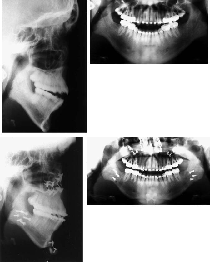
FIGURE 47.28 Preoperative (a,b) and postoperative (c,d) x-rays of patient in Figures 47.1 through 47.4. The correction involved closure of a skeletal open bite by impacting the posterior maxilla, and mandibular advancement, and an advancement genioplasty.
47. Bimaxillary Surgery and Rigid Internal Fixation |
537 |
a |
|
b |
|
|
|
c
d
FIGURE 47.29 Preoperative (a,b) and postoperative (c,d) x-rays of a severe mandibular prognathism–maxillary retrognathia corrected by maxillary advancement and mandibular reduction.
538
References
1.Abeloos J, DeClerq C, Neyt L. Skeletal stability following miniplate fixation after bilateral sagittal split osteotomy for mandibular advancement. J Oral Maxillofac Surg. 1993;51:366–369.
2.Watzke I, Turvey T, Phillips C, Proffitt WR. Stability of mandibular advancement after sagittal osteotomy with screw and wire fixation. J Oral Maxillofac Surg. 1990;48:108–121.
3.Horste W. Experience with functionally stable plate osteosynthesis after forward displacement of the upper jaw. J Oral Maxillofac Surg. 1980;8:176.
4.Carpenter CW, Nanda RS, Currier GF. The skeletal stability of LeFort I downfracture osteotomies with rigid fixation. J Oral Maxillofac Surg. 1989;47:922–925.
5.Kierl M, Nanda RS. A 3-year evaluation of skeletal stability of mandibular advancement with rigid fixation. J Oral Maxillofac Surg. 1990;46:587–592.
6.Carlotti A, Schendel S. An analysis of factors influencing stability of surgical advancement of the maxilla by the LeFort I osteotomy. J Oral Maxillofac Surg. 1987;45:924–928.
7.Perkins S, Newhouse R, Bach D. A modified Boley gauge for accurate measurement during maxillary osteotomies. J Oral Maxillofac Surg. 1992;50:1018–1019.
8.Van Sickels JE, Larsen AJ, Triplett RG. Predictability of maxillary surgery: a comparison of internal and external reference marks. Oral Surg Oral Med Oral Pathol. 1986;61:542–545.
B.Alpert, G.M. Kushner, and G.D. Verdi
9.Nishioka GJ, VanSickels JE. Modified external references measurement technique for vertical positioning of the maxilla. Oral Surg Oral Med Oral Pathol. 1987;64:22–23.
10.Booth DF. Control of the proximal segment by lower border wiring in the sagittal split osteotomy. J Oral Maxillofac Surg. 1981;9:126–128.
11.Singer R, Bays R. A comparison between superior and inferior border wiring techniques in sagittal split ramus osteotomies. J Oral Maxillofac Surg. 1985;43:444–449.
12.Linqvist C, Soderholm AL. A simple method for establishing the position of the condylar segment in sagittal split osteotomy of the mandible. Plast Reconstr Surg. 1988;82:707–709.
13.Hiatt W, Schelkun P, Moore D. Condylar positioning in orthognathic surgery. J Oral Maxillofac Surg. 1988;46:1110– 1112.
14.Rotskoff K, Heubosa E, Villa P. Maintenance of condyle-prox- imal segment position in orthognathic surgery. J Oral Maxillofac Surg. 1991;49:2–7.
15.Fujimara N, Nagova H. New appliance for repositioning the proximal segment during rigid fixation of the sagittal split ramus osteotomy. J Oral Maxillofac Surg. 1991;49:1026–1027.
16.Heffez L, Marsik J, Bressman J. A simple means of maintaining the condyle-fossa relationship. J Oral Maxillofac Surg. 1987;45:288–290.
17.Mommaerts M. Slot osteosynthesis technique for sagittal ramus split osteotomies. J Cranio-Maxillo-Fac Surg. 1991;19:147–149.