

21A
Prosthodontic Considerations in Dental Implant Restoration
James H. Abjanich and Ira H. Orenstein
Osseointegrated implant dentistry was originally developed to address the special needs of the edentulous lower jaw.1–3 Many patients who were unable to manage a complete lower denture had four to six implants placed in the anterior mandible upon which a rigid prosthesis was fabricated. From this early success, there emerged an effort to expand the uses of endosseous implants to restore a variety of edentate conditions.
As with any developing technology, dental implantology has become a highly complex and sophisticated treatment modality rooted in fundamental principles. Surgeons are opening texts from earlier school days to reacquaint themselves with the dynamics of bone biology. Similarly, restorative dentists are relearning basic biomechanical concepts. There has been a resurgence in research addressing bone healing, biomaterials, and implant biology.
The need for a strong interdisciplinary relationship between the surgeon and restorative dentist cannot be overstated. Dental implantology should be prosthetically driven. It is the patient’s intention to have dental function restored, often emphasizing a highly aesthetic result. The final prosthetic tooth position governs all phases of implant therapy. Fixture placement, possibly incorporating plastic procedures, must be executed with coordinated precision. Treatment planning and delivery is now fraught with nuances and subtleties that mandate accurate communication among the members of the interdisciplinary team. Toward that end, it is the goal of the authors of this chapter to expand the surgeon’s scope of understanding of restorative implant dentistry. It is through this sharing of knowledge that the implant team can be most effective.
Basic Principles
Surgical Stent
The surgical phase of implant placement requires a vision of the final prosthesis. The stent provides the surgeon with a three-dimensional prescription for implant placement. It will
convey the proper position, angulation, and number of fixtures to be placed. Implant diameter, length, and the relationship to anatomic structures can also be evaluated.
Radiographic markers (e.g., gutta percha, ball bearings, metal wires, barium sulfate) can be incorporated into the stent and worn by the patient during CT scanning and conventional radiographic procedures.
For the edentulous arch, a trial setup or existing ideal denture can be replicated into clear acrylic with a denture duplicating flask (e.g., Lang Denture Duplicator Flask, Lang Dental Mfg. Co., Inc., Wheeling, IL, USA). A window is cut in the stent, which defines the perimetric limits of implant placement. A perspective of the relationship between the proposed implant location and the desired tooth position is maintained. This design allows flexibility in alternate site selection. The stent should take into account flap design and be relieved to accommodate tissue retraction. It should be stable and provide good visual access to the surgical site4,5 (Figure 21A.1) while in position.
The same principles can be applied to the partially edentulous patient. A diagnostic wax-up is made on a stone model and replicated in clear acrylic as previously described. Acrylic resin is then added to the incisal and occlusal surfaces of adjacent teeth to orient and stabilize the stent. A window is made through the occlusal surfaces demarcating the potential implant sites.
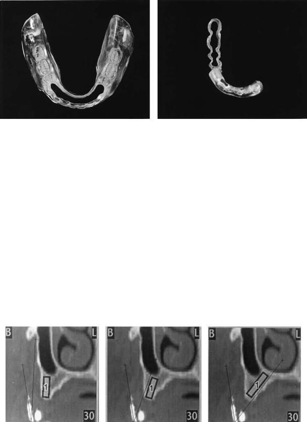
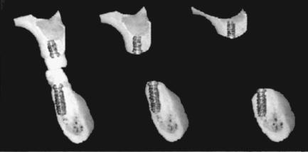
The CT scan6 can be reformatted from conventional transaxial scan images into cross-sectional views that are perpendicular to the long axis of the jaw. These reformatted images help the clinician to visualize bony topography and vital structures. Technology with computed tomographic (CT) radiology is rapidly progressing. Software (Simplant, Columbia Scientific Inc., Columbia, MD, USA) that allows the operator to superimpose implant facsimiles of different lengths and widths on reformatted images is available (Figure 21A.2). Scans taken with stents that incorporate radiopaque markers permit visualization of the labial and incisal tooth contours in relation to the bony topography and proposed implant orientation.
232
21A. Prosthodontic Considerations in Dental Implant Restoration |
233 |
a |
b |
FIGURE 21A.1 Surgical templates for the (a) completely and (b) partially edentulous mandible.
Bone
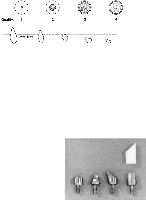
Bone quality and volume are of paramount importance to the surgeon placing implants. Lekholm and Zarb7 developed a system for classifying bone quality and volume that has become widely accepted (Figure 21A.3). Misch and Judy,8 and Jensen9 developed similar site-specific systems of bone classification. Initial rigid fixation is desirable for osseointegration to occur. This is best achieved by engaging cortical bone. Misch10 described three criteria for rigid fixation: (1) atraumatic bone preparation; (2) close adaptation of living bone to a biocompatible implant surface; and (3) absence of movement at the interface between the bone and implant during healing. He also suggested that bone quality may influence such factors as the drilling rate, sequence, countersinking, length and number of implants placed, healing time, occlusal scheme, and the need for progressive loading.
Jaffin and Berman11 reported an overall implant failure rate of 35% in quality-four (Q-4) bone using threaded titanium fixtures. Implant design and surface characteristics may influence success in various bone qualities. Manufacturers seek
to develop implant designs that lend themselves for use in poor quality bone (i.e., self-tapping implants, hydroxyapatite coatings, plasma-sprayed surfaces). It is important for the restorative dentist to consider bone quality from a biomechanical standpoint. Generally, the anterior mandible has the densest bone followed by the posterior mandible, anterior maxilla, and posterior maxilla.12 Low-density bone requires a longer healing period to maximize bony adaptation to the implant surfaces.
Forces
Implants best tolerate compressive forces.13 Compression is an apically directed force along the long axis of the implant. Tensile forces (coronally directed along the implant axis) are not as well tolerated. Shear forces (off-axis loads) have the potential to be the most destructive to the integrity of the im- plant–bone complex.
It is not always possible to position fixtures ideally to achieve optimal force distribution. The surgeon may have to
FIGURE 21A.2 Reformatted CT scan. Superimposed implant analog can be oriented to determine optimum placement. (Courtesy of Simplant, Columbia Scientific Inc., Columbia, MD, USA)
234 |
J.H. Abjanich and I.H. Orenstein |
a
b
FIGURE 21A.3 Lekholm and Zarb’s classification of bone (a) quality and (b) quantity. (From Lekholm and Zarb,7 by permission of Quintessence Publishing Co.)
angle an implant from the ideal position when bone volume is limited or in an attempt to engage cortical bone. The restorative dentist may need to modify the treatment accordingly.
It is well documented that bone density increases in relation to physiologic stress.14 The concept of progressive prosthetic loading was developed in an effort to optimize maturation of bone around implants.15,16 The restorative dentist gradually increases the forces applied to the implant–bone interface over time. This can be achieved in a variety of ways specific to the type of prosthesis. The interval between appointments may be increased to allow more time for bone remodeling to occur. Temporary removable prostheses should be frequently relined with tissue conditioner and selectively relieved. Fixed acrylic temporary restorations should initially have a narrow occlusal table, no occlusion on pontics, and no cantilever occlusion. Loads should be concentrated onto the most favorable implants. Over time, the provisional prosthesis can be modified to mimic the final result.
signs (Figure 21A.4). Standard cylindrical abutments are used where they do not compromise aesthetics (i.e., mandibular hybrid prosthesis, bar-retained overdenture). Aesthetic abutments allow the final prosthesis to end at or below the gingival margin. Angled abutments redirect the orientation of misaligned implants. The clinician can choose between abutments that employ screw or cement retention of the final prosthesis.
The use of custom abutments is becoming the procedure of choice for many practitioners (Figure 21A.5). These abutments can be waxed and cast to develop proper emergence profiles and maximize aesthetic potential. Implant alignment
Abutment Selection
In most situations the surgeon should defer the final abutment selection to the restorative dentist. A healing abutment should be placed at the time of uncovering, which emerges slightly coronal to the soft-tissue level.
The restorative dentist addresses many factors when choosing a final abutment. The proposed tooth position and contour as it relates to implant orientation will contribute to the determination of abutment length, width, and angulation. The single-tooth restoration must be antirotational. The abutmentprosthesis complex should be cleansable.17
Premachined abutments are available in a variety of de-
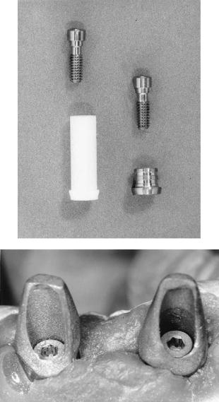
FIGURE 21A.4 Nobel Biocare abutments. (Nobel Biocare, USA, Inc., Yorba Linda, CA.) From left to right: Standard, EsthetiCone, PreAngled, CeraOne®.
21A. Prosthodontic Considerations in Dental Implant Restoration |
235 |
a
b
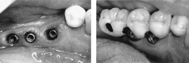
FIGURE 21A.5 (a) Implant Innovations Inc., Palm Beach Gardens, FL custom abutment components; plastic (left) and gold alloy (right).
(b) Custom abutments (viewed on soft tissue cast) fabricated from plastic UCLA-type patterns.
can be corrected to control the path of insertion of the prosthesis. Short abutments can often be milled with minimal taper and grooves to increase prosthesis retention. Abutment inventory is vastly reduced.
The recently developed high-strength all-ceramic abutments (Ceradapt™, Nobel Biocare, USA, Inc., Yorba Linda, CA) by Prestipino and Ingber in conjunction with Nobel Biocare, USA, Inc. (Yorba Linda, CA) is currently being investigated for clinical usefulness.18–20 They are said to be safe to prepare intraorally without generating heat to the implant
body and are more resistant to scratching than titanium during maintenance procedures. The aesthetic potential of these abutments is excellent.
At times, it may be difficult or impossible for the restorative dentist to choose the proper abutment intraorally. Repositioning the surgical stent may provide the necessary spatial relationship between the proposed abutment and tooth position. When selection remains difficult, it becomes necessary to directly impression the implants.21 A stone master model with implant analogs is generated and articulated at the correct vertical dimension. A diagnostic wax-up is made and a buccal putty matrix is fabricated to establish a tooth-abutment perspective. This procedure is particularly helpful when fabricating custom abutments.
Screw Versus Cement Retention of Prosthesis
Implant prostheses can be either screwor cement-retained. Many instances require this decision to be made prior to surgery as it may influence the desired implant position as detailed in the “Single Tooth Restorations” section of this chapter. When the patient has been treatment-planned to receive an anterior screw-retained prosthesis, it is generally advisable to direct implants for the access hole to exit the cingulum area. This will often necessitate placing a labial ridge-lap to meet aesthetic demands. The screw-retained prosthesis access channel can interfere with aesthetics if an implant is angled too far labially and can compromise the tongue space when oriented lingually. Angled abutments can redirect the access opening. When using UCLA-type abutments that screw-retain the prosthesis directly to the implant body (i.e., because of limited intermaxillary space or for better control of emergence profile) redirection of the access opening is impossible. Lingually positioned fixtures are often best restored with a one-piece screw-retained prosthesis to reduce bulk, which could otherwise affect phonetics and comfort (Figure 21A.6). Difficult cases that require screw-retention with fine control of exit holes can sometimes be restored with prostheses that incorporate mesostructures (see the “Complications” section in this chapter). These restorations are often very complex, costly, and bulky, reinforcing the need for accurate implant placement.
Cemented prostheses eliminate the aesthetic and surgical limitations associated with the screw access opening. Custom abutments often employ cement retention of the overlying prosthesis and offer the greatest control of emergence profile and aesthetics.
The restorative dentist may not wish to place a cementretained prosthesis where intermaxillary space is limited. Alveoloplasty and/or countersinking of implants below the crest of bone might otherwise be necessary to achieve the height requirement for cement retention. The decision to do this is not without potential consequences as the surgeon may be sacrificing precious crestal cortical bone and reducing the
236 |
J.H. Abjanich and I.H. Orenstein |
a |
b |
FIGURE 21A.6 (a) Severe lingual placement of implants. (b) One-piece screw-retained restoration minimizes lingual bulk.
potential implant length. In such situations, a screw-retained prosthesis may be the better choice as the vertical height requirement is less.
The cemented prosthesis is more likely to fit passively than its screw-retained counterpart. This factor is important to the surgeon and restorative dentist troubleshooting the ailing implant. A screw-retained prosthesis that does not fit passively may induce implant overload with potential failure if not corrected.
The restorative procedures associated with cemented prostheses closely parallel those of the conventional crown and bridge.22
Completely Edentulous
Many edentulous patients are unable to function with conventional complete dentures. Patients with advanced bone resorption and thin overlying mucosa have ridges that provide minimal stability and resistance to motion. This causes continual irritation and limits mastication and speech. Other patients cannot tolerate a palatal section due to severe gagging. A small group is psychologically unable to confront their edentulous state and completely rejects the concept of complete dentures.23 These concerns have made dental implantology useful for the restoration of many edentulous arches.
Immediately following the extraction of all teeth in an arch, bone is rapidly resorbed.24 During the first year of edentulism there is an average decrease in bone height of 4 to 5 mm in the mandible and 2 to 3 mm in the maxilla.25 A ratio of 3 or 4:1 has been demonstrated for long-term bone loss of the mandible and maxilla, respectively. Carlsson found the mean mandibular height reduction 5 years after tooth extraction to be 12.5 mm (ranging from 2 to 14.5 mm).26 Patients who have initial rapid bone loss tend to continue to demonstrate greater long-term ridge resorption. There is a poor correlation between ridge size and time of edentulism as significant individual variation exists.
The maxillary edentulous arch will resorb in a superior and lingual direction. The outer cortical plate is thinner, and as a result, resorption from the facial aspect tends to be more rapid. As the maxilla resorbs, it becomes smaller in all dimensions. The mandibular outer cortex is generally thicker than the lingual except in the molar region. The mandibular width is greatest at its inferior border and therefore appears to widen in the posterior region as resorption progresses in an inferior and lateral direction.
The horizontal and vertical bony resorptive patterns produce narrowing of the maxilla and expansion of the mandible.27 The resulting unfavorable ridge relationships can have many effects. The decrease in maxillary anterior arch circumference necessitates unfavorable lingual implant placement, a poor crown-to-implant ratio, and reverse occlusion (crossbite)28 (Figure 21A.7).
Although the mandible suffers a greater magnitude of resorption, restoration of the edentulous maxilla remains more challenging. The anterior mandible widens toward the inferior border. The absence of a mandibular residual ridge does not influence the use of implants since the width and depth of basal bone below the floor of the mouth is usually substantial with a prominent inferior cortex.29 It is usually possible to place fixtures here in the presence of advanced resorption. On the contrary, the maxillary ridge may resorb yielding bone that is too narrow and of insufficient height. The nasal fossa and maxillary sinus may limit implant length.
The aesthetic considerations are very different for both jaws. Aesthetic restoration of the mandible is usually straightforward because the interface between the implant abutments and prosthesis is well hidden by the lower lip. Conversely, the upper arch carries with it a host of aesthetic and functional concerns. The implant-prosthesis interface will sometimes be visible, thereby necessitating meticulous fixture placement within the confines of the body of the prosthetic tooth. The restoration will often employ aesthetic abutments. The maxillary prosthesis may require a prosthetic flange to replace hard and soft tissue for facial support. A major concern with any maxillary pros-
21A. Prosthodontic Considerations in Dental Implant Restoration |
237 |
thesis is speech-related to air flow and tooth position. Air that escapes between the superior aspect of the prosthesis and the ridge can most profoundly affect fricative sounds (f, v, th, s, z, sh, j, ch). Lingual implant placement and a concurrent palatally placed prosthesis may disrupt lingual alveolar sounds (t, d, n, l). In many situations, therefore, restoration of the edentulous maxilla is best accomplished using an overdenture.
Full-arch implant-supported restorations can be fixed (screwor cement-retained) or patient-removable (overdenture). The fixed restoration can be porcelain fused to metal or a hybrid prosthesis using acrylic resin to affix stock denture teeth to a custom frame. Overdentures can incorporate varying degrees of tissue support and can be retained by bars and retention clips, stud attachments, or magnets.
The spark erosion restoration has the rigidity of a fixed prosthesis coupled with the advantages of a conventional implant-retained overdenture as will be discussed in the “Edentulous Maxilla” section of this chapter.
Several factors should be considered when choosing between a fixed or removable restoration.30 Fixed prostheses are usually preferred by the patient whenever possible. They require sufficient fixture support and distribution. The cantilever length will depend upon the amount of implant support, bone quality, crown-to-implant ratio, anteroposterior (A-P) spread (to be discussed in the “Fixed Mandibular Reconstructions” section of this chapter) and opposing occlusal forces. When facial support from hard and soft tissues is correct a fixed option is often preferred. Trial setups with and without a flange can determine whether additional support is necessary. Fixed reconstructions may be preferred when knife-edged ridges with minimal denture-bearing area provide poor support for tissue-borne overdentures. Fixed restorations generally require less interarch space. The removable overdenture may require less complicated treatment planning and decreased expense. It is indicated when confronted with less bone for fewer implants. Overdentures allow greater ease for achieving aesthetics. They should be used when a flange is necessary to support facial structure that has been lost from resorption or trauma. Removable
FIGURE 21A.7 Progression of bone resorption in the maxilla and mandible as it relates to implant position. (From Bahat,28 by permission of Int J Oral Maxillofac Implants)
flanges can be fabricated for fixed reconstructions, but they are usually not durable and attract plaque. Overdentures may be indicated when increased functional capacity of a fixed prosthesis may exceed the load-bearing limit of a weaker opposing jaw.31 A fixed restoration should never be promised to a patient. The treatment plan should always be flexible, and the overdenture restoration should not be viewed as a second-rate service (Figure 21A.8).
Edentulous Mandible
Fixed Mandibular Prosthesis
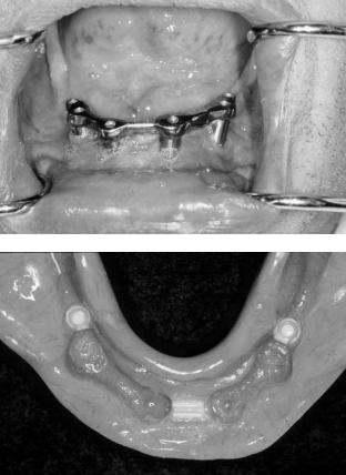
The high level of implant and prosthesis stability associated with mandibular osseointegrated restorations is well documented.32,33 Adell32 reported that 99% of mandibular prostheses remained continuously stable through a 15-year follow-up period; 100% fixture survival is not required for continuous prosthesis stability when adequate fixture redundancy has been incorporated into the treatment plan. The high success rate is reflective of the good bone quality generally found in the anterior mandible. Brånemark’s original protocol called for the placement of four to six fixtures between the mental foramena. The prosthesis was connected to an abutment cylinder via a gold screw. This gold screw is the weak link and will protect the implant from potential overload. It is preferable for the prosthesis or abutment retaining screw to break prior to loss of integration or implant fracture. The classic mandibular prosthesis is a hybrid design, which uses acrylic resin to process stock denture teeth to a screw-retained precisely fitting framework.
The success of implant-retained prosthodontic restorations depends largely on the ability to achieve a precise, passive fit. The healthy natural tooth will typically flex 100 m vertically and horizontally. The fixture will hardly flex (10 m vertically and horizontally).33 Carlsson demonstrated that an angular prosthesis gap of 50 m requires a 200- m correction of the fixture apex to alleviate the resultant forces.34 Any stress produced by the prosthodontic restoration will remain
238
a
c
e
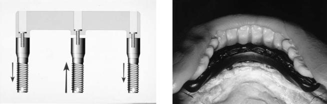
there since the rigid implant has limited adaptability.35 It is therefore critical to minimize static misfit forces. Even when the prosthesis appears to clinically have an acceptable fit, a significant force may be introduced when the framework is screwed into position (Figure 21A.9).36
Transfer Copings for Master Cast Fabrication
Precise reproduction of implant position with the master cast is imperative especially for screw-retained prostheses. Con-
J.H. Abjanich and I.H. Orenstein
b
d
FIGURE 21A.8 Implant restoration of the fully edentulous patient. (a) Mandibular fixed hybrid prosthesis with view of maxillary overdenture substructure. (b) Occlusal view of overdenture substructure. The surgeon must know where the attachments will be placed to properly space implants. (c) Retentive clips in maxillary overdenture. (d,e) Final restoration.
troversy surrounds the issue of master-cast accuracy derived from open-tray square transfer copings (direct technique) versus smooth unsplinted copings (indirect technique). Assif37 and Carr38 concluded that splinted square copings retained in the impression were better than tapered unsplinted transfer copings that were reseated. Zarb39 suggested affixing floss along square abutments to form a matrix for resin splinting. Self-cure acrylic shrinks upon polymerization. Ivanhoe40 advocates splinting copings on a preliminary cast with light-cured resin, while Lechner41 uses autopolymerized acrylic. The resin
21A. Prosthodontic Considerations in Dental Implant Restoration
FIGURE 21A.9 A screw-retained prosthesis with a misfit will generate destructive tensile forces.
splint is sectioned and reattached intraorally to minimize distortion when fabricating the master model. Barrett42 found no significant difference between splinted and unsplinted square copings. The tapered copings, however, had decreased accuracy in the vertical axis. Contrary to other studies, Humphries43 concluded that unsplinted tapered copings (that are reseated into the impression) reproduced the greatest accuracy.
Transfer copings that can be retained in impression material do not have to be reseated, thereby eliminating a potential source of error. Copings splinted with acrylic should be sectioned and reannealed with minimal material to reduce distortion. Tapered copings that are reseated may need to be used in limited access regions as they require less vertical height.
Verification of the Master Cut
Prior to fabricating the wax pattern, verification of the master cast accuracy41,44 will minimize sectioning and resoldering of frameworks. Gold cylinders can be placed on the abutment replicas and connected with acrylic resin. The joints are sectioned and reconnected with minimal material to reduce polymerization shrinkage. The assembly is checked in the mouth to verify acceptable clinical fit, which is usually agreed to be within 30m. If the index is inaccurate, it is sectioned and reannealed in themouth,andacorrectedstonemastermodelisgenerated.Each subsequent step (i.e., porcelain application) can be checked for distortion by replacement of the prosthesis on the verified master model. All cylinders must simultaneously seat without tightening multiple screws. One terminal screw is placed, and the fit of the prosthesis checked. If this is acceptable the other terminal screw is inserted and the original one removed. Intermediate screws can then be placed and fit reassessed. For cementretained prostheses, master-cast verification may be less critical.
Substructure Fabrication
Prior to substructure fabrication, a diagnostic setup should be verified in the patient’s mouth to establish aesthetics, pho-
239
FIGURE 21A.10 Facial putty matrix with denture teeth guides the technician with substructure wax-up.
netics, vertical dimension, and occlusion. A putty matrix is constructed to relate the final tooth position to the master cast (Figure 21A.10). The substructure is correctly waxed to be strong and rigid and to adequately support the veneering material (denture teeth or porcelain). Porcelain is particularly vulnerable to fracture if it is not properly supported. Substructure thickness when using porcelain veneering with implants compared to natural teeth can result in a much thicker metal frame. This has the distinct advantages of reducing flexure and decreasing the possibility of tensile fracture of porcelain. The increased rigidity permits distribution of static loading more evenly thereby decreasing the potential for sudden impact loading with better distribution to the implants.45
Gold and silver-palladium are the most popular materials employed to fabricate substructures. Recently, Nobel Biocare, USA, Inc. (Yorba Linda, CA) introduced Brånemark System Custom Solutions’ Procera method to fabricate accurate titanium frameworks.46,47 The process begins with the creation of a light-cured resin substructure, which is sectioned into several pieces. Prefabricated titanium rod stock elements that include the abutment (standard or Estheticone) are placed in a copy milling machine (similar to a key cutter) with the resin pieces to replicate their shape. The resulting individual titanium elements are welded with a stereo laser that minimizes framework warpage. This technology produces the most accurate fitting frameworks to date (less than 30- m gap on master model analogs).
Biomechanical Considerations for Mandibular Fixed Reconstructions
The final prosthetic treatment decision is based upon several biomechanical factors. They include the number, length, and angulation of fixtures, bone quality, crown height to implant ratio, opposing occlusion, and the A-P (anteroposterior) spread48 of implants.
The classic lower fixed implant reconstruction has five to six fixtures placed between the mental foramena. Four have
240
been used when opposing a complete denture with all other factors favorable. However, the prosthesis is at a greater risk of failure in the absence of fixture redundancy. When fixtures are not placed distal to the mental foramina, cantilever extensions are necessary.
There is considerable variation in the literature regarding proper cantilever extension. Mandibular cantilever lengths have been suggested not to exceed 20 mm49,50 (while not exceeding 10 mm in the maxilla). Shackleton51 reported significantly better prosthesis survival when cantilevers do not exceed 15 mm. The A-P spread will have a profound effect on this decision.
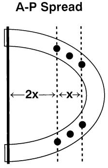
The A-P spread is the distance between the fulcrum and a line through the most anterior implant (Figure 21A.11). A curved implant distribution is more capable of resisting the bending moments generated on cantilever sections. Calculations reveal that posterior cantilever extensions should be less than two times the A-P spread.52 A horizontal arrangement of four to six fixtures would therefore not adequately support a customary cantilever length. Other factors that decrease potential cantilever length include opposing natural dentition, poor bone quality, short or poorly angled implants, poor crown-to-implant ratio, parafunction, and fewer than six implants.
Severely resorbed mandibles can sometimes have an extremely unfavorable crown-to-implant ratio of 3:1. When this is coupled with a poor A-P spread the potential for overload exists, and a fixed prosthesis may be contraindicated.
FIGURE 21A.11 A-P spread. Cantilever extensions (2 ) should never exceed two times the distance between the anterior fixture(s) and posterior fulcrum ( ).
J.H. Abjanich and I.H. Orenstein
Lindqvist et al.53 found that biting force on a cantilever results in compression (better accepted by fixtures) on the distal fixture and tension (potentially destructive) on the anterior fixture. As a result, medial fixtures show more bone loss when compared to the distal fixtures (fulcrum). Sullivan54 demonstrated that an additional 5-mm separation of the distal fixtures decreases the tensile forces by 2.5 times. White et al.55 used a photoelastic model to demonstrate that the highest stresses from forces exerted on distal cantilevers are concentrated on the ridge crest of the distal surface of the distal implant.
Situations arise in which more posterior occlusion is necessary than can be cantilevered from fixtures between the mental foramina. The lower anterior teeth are often the last to be lost. Patients who have worn an upper complete denture over a removable partial prosthesis with natural anterior teeth may have severe maxillary anterior ridge resorption with flabby redundant tissue. A fixed lower implant-supported bridge with only bicuspid occlusion may yield a tipping and unstabilizing effect, whereas a complete denture or overdenture can provide a full complement of posterior teeth. Alternatively, additional fixtures can be placed posterior to the mental foramina to fabricate a fixed prosthesis. Bruxers may also benefit from additional posterior implant placement. Zarb56 reported fractures of abutment screws and gold screws despite accurate framework fit and proper occlusion.
Patients with a full complement of maxillary molars (concerns for supereruption) and those who desire more posterior occlusion may require additional posterior fixtures.
Anterior and posterior fixtures splinted in one piece around the lower arch may subject the bone–implant interface to stress-induced microdamage due to the flexure inherent in the mandible on opening.57 With sufficient posterior fixtures, the fabrication of three independent sections should be considered. When only one terminal fixture can be placed on both sides, the concept of cantilever rests58 can be incorporated. These distal fixtures are not rigidly connected to the framework. They function as vertical stops that reduce torque on anterior fixtures, thereby negating the harmful effects of long cantilevers.
Veneering Materials
Biomechanical concerns have been raised addressing the need to dampen impact forces on osseointegrated implants.59 Various ways to reduce impact load have been suggested. The intramobile element used in the IMZ system is said to simulate the periodontium. Brånemark suggested the use of acrylic resin occlusal surfaces to decrease impact stresses. A study by Gracis et al.60 showed resin to decrease impact force 50% over metal and porcelain occlusal surfaces. Davis suggested that porcelain is more appropriate than resin for patients who brux.61 Porcelain will stiffen the framework and provide more even stress distribution to implants. Naert62 has clinically shown that when compared to resin, porcelain as an occlusal
21A. Prosthodontic Considerations in Dental Implant Restoration
material did not influence the marginal bone height around implants. To date, the clinical significance of impact loading of implants and its relationship to occlusal materials remains unanswered.
Resin and porcelain each have specific indications. Both have a long record of success with conventional dental restorations. Resin is usually indicated when the opposing occlusion is of the same material. Porcelain is more color stable. When porcelain is used, one should consider the potential for framework distortion during firing. For longer spans, postsoldering of shorter sections will minimize this effect. Acrylic wears more rapidly than porcelain and therefore can create iatrogenic occlusal changes over time.
Occlusal Considerations
When considering an occlusal scheme, the weakest component concept should be employed. When a lower fixed osseointegrated reconstruction opposes a maxillary complete denture, the bone of the premaxilla must be protected. There should be no anterior contacts in centric, and a balanced occlusion is developed in excursions. The masticatory forces generated with a fixture-assisted lower fixed prosthesis approach that of the natural dentition. This increased biting force may result in fracture of a previously stable maxillary denture. It is therefore advisable to incorporate cast metal reinforcement in the opposing prosthesis.
When a lower fixed fixture-assisted bridge opposes another implant bridge or natural dentition, a mutually protected occlusion is developed. Protrusive and lateral excursions on the anterior teeth will disclude the posterior dentition, thereby protecting distal cantilever extensions and implants placed in soft bone from lateral forces.
When full-arch implant reconstructions oppose each other, emphasis is placed on protecting the upper cantilevers. If the upper arch has an anterior cantilever and the lower has posterior cantilevers, protection of the upper prosthesis will usually still take precedence.
Removable Mandibular Prosthesis
Brånemark’s original prosthodontic protocol called for a screw-retained fixed prosthesis that could not be removed by the patient. The use of overdentures retained by two or more fixtures has since been proven to be successful. Multicenter studies demonstrate mandibular overdenture success rates similar to those observed for fixed prostheses.63,64 Feine et al.65 found long-bar mandibular overdentures to provide similar chewing efficiency when compared to mandibular fixed full-arch prostheses. Overdentures have several advantages over complete dentures. Prosthesis retention, stability, tissue sensitivity, oral hygiene, chewing efficiency, and speech are improved. Bone atrophy is reduced. After the extraction of mandibular anterior teeth, there is an average of 4 mm of vertical bone loss in the first year. The mandible will have a four-
241
fold greater loss of height when compared to the maxilla during the next 25 years.66 With the placement of overdenture fixtures long-term bone loss may stabilize at 0.1 mm per year around implants. A reduced extension of the lingual denture flange may improve patient comfort and tongue mobility without necessarily sacrificing function.67 Overdentures may be indicated for maxillofacial patients who have undergone resective surgical procedures.
Overdentures present several advantages over fixed appliances. Fabrication time and cost may be reduced. Hygiene access is improved. Overdentures can replace lost facial support. Sometimes fixture support is insufficient to place a fixed prosthesis. Overdentures provide more posterior teeth to function against the opposing arch (when compared to a fixed prosthesis with distal cantilevers).
Several design considerations should be addressed depending on the number and distribution of implants. Bars with retentive clips as well as ball attachments have been used successfully.
Corrosion and tarnish of intraoral magnets have raised questions as to their acceptability for intraoral use.68
Bar-Retained Overdentures
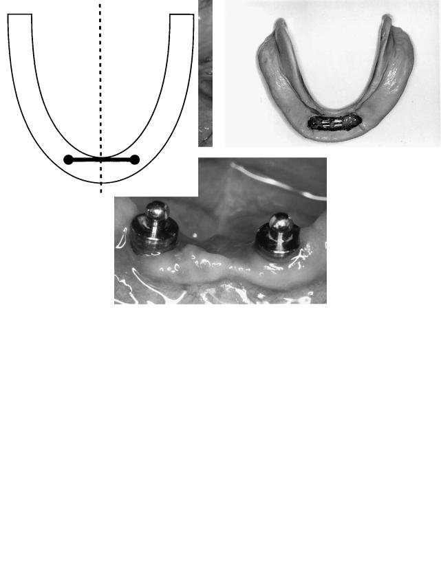
Two implants supporting a bar can effectively stabilize a lower denture (Figure 21A.12). Rotation of the prosthesis around the bar permits the soft tissue to share the occlusal load and minimizes torsional forces on the implants. To achieve this the bar and clip must be perpendicular to the sagittal plane69 (Figure 21A.13). These same principles apply when restoring toothsupported bar-retained overdentures.70
The shape of the bar will influence rotation. A round bar (e.g., Hader bar, APM Sterngold, Attleboro, MA, USA) allows free rotation. The pear-shaped Dolder bar (APM Sterngold, Attleboro, MA, USA) permits less rotation, and finally the parallel-sided Dolder bar allows the least amount of movement. The two fixtures should be placed in the canine regions. If additional implantation for a future fixed prosthesis is anticipated, a site between the implant and mental foramen should be preserved. A distal bar extension should never be used with two implants.
Three-splinted implants will greatly negate the ability of the denture to rotate if there is no straight bar section perpendicular to the sagittal plane. The third implant is sometimes placed for security to maintain the viability of the overdenture prosthesis in the event of implant failure. It is sometimes possible to cantilever a small section with retentive elements distal to the last fixtures when opposing a stressbroken prosthesis.71 The addition of these cantilever extensions must be weighed against the potential introduction of implant overload.
Four implants can sometimes support a fixed prosthesis but will also act as well-positioned overdenture abutments. Two fixtures are placed in the cuspid sites and two just anterior to the mental foramina. A clip will be placed anteriorly, and re-
242 |
J.H. Abjanich and I.H. Orenstein |
a |
b |
c
FIGURE 21A.12 (a) Mandibular implant-supported overdenture bar, (b) denture with retentive clips, and (c) stud attachments. Bar and stud attachments can significantly stabilize a mandibular denture.
FIGURE 21A.13 A mandibular overdenture bar when supported by two implants should be oriented perpendicular to the midsagittal plane.
silient extracoronal attachments are situated immediately distal to the posterior fixtures. Rotation of the denture and posterior lifting are significantly reduced (Figure 21A.14a,b).
Tissue-supported mandibular overdentures generally function better in the presence of adequately attached gingiva as the tissue borders are more stable.
Overdentures can be totally implant-supported in some situations when five or more implants are present.
Stud-Retained Overdentures
Naert et al.72 found no difference in implant success or clinical performance of prosthetic treatment in the mandible for two nonsplinted versus splinted implants. A variety of stud attachments are available to retain mandibular overdentures. The ball attachment has been widely used with great success.73 This prefabricated mechanism is less expensive and quicker to fabricate than a cast or soldered bar. The appropriate height (1 to 2 mm above the gingiva) is selected, and the attachment is screwed directly into the implant. The female retaining cap is inserted into the denture with autopolymerizing acrylic (Figure 21A.12c).
21A. Prosthodontic Considerations in Dental Implant Restoration |
243 |
a |
illary treatment plan should be overengineered, calling for |
|
the placement of as many properly positioned implants as is |
|
possible. |
b
FIGURE 21A.14 (a) For implant design with splinted bar. “Passive” rotation from anterior clip and posterior resilient attachments. (b) Denture with anterior clip and posterior ERA attachments.
Occlusal Considerations
The mandibular overdenture should have a balanced scheme of occlusion. There are no anterior contacts in centric. In protrusive and lateral excursions, both anterior and posterior teeth will touch.
Edentulous Maxilla
The edentulous maxilla presents the greatest challenge to implant reconstruction. Aesthetic demands, anatomic limitations, resorption patterns, and phonetic considerations are just a few of the many restorative concerns that must be addressed. The variability of implant placement will also require flexibility in the design of the final prosthesis. The patient should never be promised a maxillary fixed restoration. The need to replace lost facial support will require most maxillary arches to be restored with overdentures or spark erosion prosthesis.
It is more difficult to achieve and maintain osseointegration in the maxilla. The fixture survival rate decreases approximately 10% from that found in the mandible.1 It is wise to employ the concept of fixture redundancy. Ideally, the max-
Significance of Maxillary Resorption Patterns
As the maxilla resorbs, the ridge moves superior and medial. The bone available for implant placement is therefore often palatal to the original tooth position. This may result in crowding of the tongue and compromised speech. A posterior crossbite or labial cantilever may be necessary to regain former tooth relationships. Anterior teeth positioned for esthetics and phonetics may be far removed from the implants. Labial resorption can result in lost facial support, which can be restored with a labial flange. An overdenture or spark erosion prosthesis will permit optimal hygiene maintenance when a flange is required.
The extent of ridge resorption has been classified by Desjardins as minimal, moderate, or severe.74 This greatly influences prosthesis design.
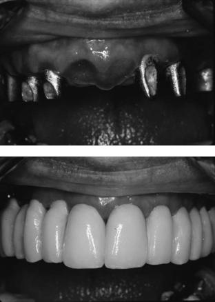
Minimal resorption usually permits fabrication of a fixed restoration. This is generally found in newly edentulous patients or patients who will be rendered edentulous. The fixtures can therefore be placed in an appropriate buccolingual, mesiodistal, and coronogingival position to support aesthetic, phonetic, and emergence profile requirements. This situation lends itself to the use of ceramometal restorations (Figure 21A.15a,b). Implants can be placed where the teeth previously existed. Ideal biomechanical distribution of six or more fixtures is often possible.
Moderate resorption will usually require a labial flange to restore facial support and esthetics. Overdenture therapy is often indicated. If sufficient fixture support and distribution is possible, a spark erosion prosthesis can be used. Diagnostic setups with and without a labial flange should be used to determine whether additional facial support is necessary.
Severe resorption may require bone grafting procedures. There is insufficient bone height, and what is present is in a palatal position. Whenever possible, implant placement with simultaneous bone grafting will save considerable time. These patients should almost exclusively be treated with overdentures as precise fixture positioning is hard to achieve.
Maxillary Implant Positioning and Distribution
The maxilla can be divided into three regions when discussing implant location.
The cuspid area generally provides the most predictable location with good bone height, width, and arch position.75 It should be viewed as the primary site for implant placement.
The posterior areas vary as potential regions for implant placement. It is not uncommon to find Q-4 bone here, reinforcing the need for as much fixture support as possible. The maxillary sinus may limit bone height and width. There is a higher failure rate with 7-mm fixtures.76 Where less than
244 |
J.H. Abjanich and I.H. Orenstein |
a |
maxilla. During the first year of function, speech problems were |
|
the most common patient complaint. The most frequent ad- |
|
justments to the prosthesis were related to resin fracture. |
|
The maxillary fixed prosthesis can be fabricated with porce- |
|
lain fused to metal or as a hybrid case. When a porcelain-to- |
|
metal restoration is considered, ideal implant placement is |
|
imperative to optimize aesthetics, phonetics, and effective hy- |
|
giene. The fixtures must be positioned mesiodistally within |
|
the tooth confines. Interproximal or lingual fixtures will com- |
|
promise aesthetics. A flange may be necessary to hide the im- |
|
plant(s), complicating hygiene access. The fixture head should |
|
be positioned 2 to 4 mm apical to the marginal tissue and exit |
|
just palatal to the proposed labial gingival interface. Local |
|
bone anatomy may prevent ideal implant placement and re- |
b |
quire the use of angled or custom abutments. |
|
The maxillary hybrid design must be very different than its |
|
mandibular counterpart. The mandible classically shows 2 mm |
|
of abutment to facilitate hygiene. The maxilla has stringent |
|
requirements. Air and salivary flow between the top of the |
|
prosthesis and the ridge may compromise speech. The pros- |
|
thesis should be initially abutted to the ridge crest. The bor- |
|
ders can be later adjusted as needed for hygiene access. |
|
Maxillary Removable Prosthesis |
|
|
The maxillary overdenture is indicated when lost facial sup- |
|
|
port necessitates the use of a prosthetic labial flange. Hygiene |
|
|
will be greatly facilitated with this design. Flanges incorpo- |
|
FIGURE 21A.15 (a) Full arch implants restored with custom abut- |
rated into fixed restorations compromise hygiene access. Fix- |
|
ments. (b) Porcelain fused to metal cemented prosthesis. |
ture number and distribution may biomechanically rule out |
|
|
the possibility of a fixed restoration. Overdentures usually |
|
|
permit tissue support to assist the implants with force dissi- |
|
10 mm of bone is available in the sinus region a graft should |
pation. Treatment cost and time are often less than for fixed |
|
be considered. Wide-diameter implants may sometimes be |
prostheses. |
|
used under the sinus. They have increased surface area re- |
The implant failure rate associated with maxillary over- |
|
quiring less fixture length, and may also engage buccal and |
dentures is higher than reported for fixed implant prosthe- |
|
lingual cortical bone. |
ses.79 This fact supports the recommendation that the maxi- |
|
The anterior areas provide the third region for implant |
mum number of implants be placed when fabricating an upper |
|
placement. If sufficient bone exists to place fixtures in the ca- |
overdenture. Rotation and torquing associated with overden- |
|
nine and posterior regions, it may be possible to fabricate a |
tures may contribute to their increased failure rate. Langer80 |
|
fixed prosthesis without involving the premaxilla77 if doing |
suggests rigidly splinting maxillary fixtures to compensate for |
|
so would compromise aesthetics or create excessive bulk in |
the less-favorable bone quality. Unsplinted stud attachments |
|
an overdenture. Where possible, two fixtures can be placed |
in the maxilla have been associated with a higher failure rate |
|
in the central incisor sites. Fixtures should not be placed lin- |
than splinted maxillary implants supporting overdentures. In |
|
gual to the incisive papilla as this can affect speech and re- |
the presence of adequate fixture and facial support the po- |
|
strict tongue movements. |
tential for overload may be better controlled with a fixed |
|
As a general rule, prudence dictates the placement of as |
restoration. Overdenture maintenance is greater than for fixed |
|
many implants as is possible when restoring the edentulous |
prostheses supported by implants.81 Fatigue fractures of the |
|
maxilla. |
resin and clips along with mucosal problems surrounding im- |
|
|
plants have been observed. Fewer phonetic disturbances have |
|
Maxillary Fixed Prosthesis |
been documented. |
|
It is imperative that the surgeon knows where the restora- |
||
|
||
Jemt78 reported a 5-year cumulative fixture and prosthesis sur- |
tive dentist plans to place attachments so that the implants |
|
vival rate of 92.1% and 95.9%, respectively, for fixed pros- |
can be spaced to accommodate them. Attachment mechanisms |
|
theses supported by osseointegrated implants in the edentulous |
near the incisive papilla should be used judiciously as over- |
21A. Prosthodontic Considerations in Dental Implant Restoration
bulking of the prosthesis in this region can annoy the tongue and interfere with phonetics.
Maxillary Spark Erosion Prosthesis
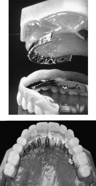
The spark erosion prosthesis combines the best aspects of both the fixed and removable design.82 A primary 2° tapered milled bar is fabricated on the master cast. The secondary casting is made to fit over the primary bar with great intimacy via the spark erosion process. Retention comes from the minimal taper, parallel pins, and direct swivel latch attachment. The swivel latch is placed on the lingual of the upper (and labial of lower) prosthesis.
245
This prosthesis is totally implant-supported and will have the retention and function of a fixed restoration while maintaining the advantages of a removable design. A labial flange can be incorporated, and correct tooth position achieved. The patient can easily remove the prosthesis by unlocking the lingual swivel latch, facilitating hygiene access (Figure 21A.16a,b).
Partially Edentulous
Clinicians have expanded the use of endosseous implantology to treat the partially edentulous patient. Naert et al.83 demonstrated a cumulative implant success rate of 96.1% and 95.9% for the maxilla and mandible, respectively, during a 6-year prosthodontic study. Jemt et al.84 found 98.6% implant success with free-standing fixed partial prostheses after 1 year. Zarb and Schmitt85,86 experienced 94.3% fixture survival during 2.6 to 7.4 years of loading for the posterior partially edentulous and a 91.5% implant success rate for anterior restorations during loading periods ranging from 2 to 8 years. These studies support the consideration of endosseous implantology as an adjunct to restoring the partially edentulous arch.
Sullivan87 notes that approximately 17 to 20 million Americans are partially edentulous. Implant-supported prostheses can be considered for those patients who experience difficulty wearing a removable partial denture. This is a common finding in patients with unilateral edentulism. Implant-supported prostheses may also provide an acceptable alternative to extensive crown and bridge procedures on natural teeth.
Bone density and volume often present problems when considering implant-borne restorations. Knife-edged ridges often necessitate extensive alveoloplasty. The mandibular canal, maxillary sinus, and nasal fossa may limit implant length.
a
b
FIGURE 21A.16 Maxillary spark erosion prosthesis. (a) Milled bar with mating prosthesis. (b) Prosthesis has the stability of a fixed restoration.
Posterior Considerations
The mandibular canal often limits implant length. When the posterior mandible has a broad bony base, a wide-diameter implant may be considered, which can engage the buccal and lingual cortical plates for greater stability. Wide implants increase the bone–implant interface when vertical height is limited. They also provide a better emergence profile for molar teeth and improved axial loading (Figure 21A.17a,b). Bone augmentation may sometimes be considered. Reformatted CT scanning may permit good visualization of the relationship of the mandibular canal to the proposed implant orientation. It is sometimes possible to use a longer fixture by placing it buccal or lingual to the canal. The mandibular nerve has been surgically repositioned to permit longer implant placement.88
The posterior maxilla often presents several obstacles to achieving predictable implant rehabilitation. Kopp89 stated that the replacement of bilateral posterior edentulous areas in the maxilla with osseointegrated implants is difficult if not impossible. Bone density in this region tends to be the

246
a
b
FIGURE 21A.17 (a) Radiograph: the combination of wide platform molars and standard premolar allows for more natural emergence profile. (b) Screw access chambers in final prosthesis.
poorest with Q-3 and Q-4 bone being a common finding. The surgeon may prefer to use self-tapping implants in softer bone to avoid stripping bone threads, which can occur during standard tapping procedures. Alternatively, press-fit implants that are easier to install may be considered. Maxillary bone resorbs from buccal to lingual, often necessitating that restorations be cantilevered buccally for proper cheek support and occlusion. The maxillary sinus tends to pneumatize with age, reducing the amount of vertical bone height available for implant placement. A reformatted CT scan may be indicated to relate proposed implant placement to the orientation of the maxillary sinus. Wide implants, maxillary sinus bone augmentation, or both may be considered when bone height is limited.90 It is generally recommended that the surgeon wait 9 months to 1 year before uncovering implants that have been placed in the posterior maxilla that was treated with sinus augmentation (a great variation in healing times has been reported for various graft materials91). Carefully planned onlay grafts that do not encroach excessively on intermaxillary space can improve the crown-to-implant ratio.
Clinicians may encounter difficulty working in the posterior regions of patients with limited intermaxillary opening. When this occurs, it may be advantageous to employ press-
J.H. Abjanich and I.H. Orenstein
fit implants as the osteotomy site is easier to prepare and placement does not require mounting tools. Tilting the implants slightly mesially may permit easier access for the surgeon and restorative dentist. Impressioning of implants or abutments using the indirect coping technique described earlier requires less vertical space.
Supereruption of teeth opposing an edentulous area may limit intermaxillary space. Occlusal equilibration with possible tooth devitalization and periodontal crown lengthening may be necessary (Figure 21A.18). Segmental osteotomy may be considered when supereruption is severe. Alveoloplasty of the edentulous ridge may also be performed when sufficient bone will remain for fixture placement.
Biomechanically, implants tolerate forces better when they turn the arch to create a curved support system.92 Posterior partially edentulous restorations often have the implants oriented in a straight line in response to jaw anatomy, creating a distinct mechanical disadvantage. Furthermore, molar biting forces can be four times greater than in the incisor region.13 These factors, coupled with the lower bone density, decreased available bone height, and maxillary buccal cantilevering often encountered in the posterior region, suggest the need for careful treatment planning for posterior partially edentulous restorations. Implant support should be maximized, and progressive loading as described earlier should be considered. A mutually protected occlusion that disarticulates the posterior prosthetic teeth in lateral excursions is recommended (lateral forces generate shear stresses on fixtures).
Anterior Considerations
Anterior restorations often present several challenges. Implants must be positioned to permit natural tooth emergence angles, particularly for the patient with a high smile line. Fixtures placed too lingually compromise the tongue space and interfere with phonetics. Lingual or interproximal positioning may require ridge-lapping of the final prosthesis, which can complicate oral hygiene procedures. The nature of bone resorption in the anterior maxilla often necessitates that implants be directed labially. The restorative dentist must compensate by using angled machined abutments or custom abutments or mesostructures to redirect the implants. In severely resorbed, defective, and injured ridges bone grafting may be required to idealize implant positions on placement.
Final tooth position for anterior restorations commonly creates a mutually protected occlusion that disoccludes posterior teeth in excursions. Anterior implants may therefore be exposed to lateral forces. The consequences of this are not known to date. Fortunately in the maxilla, the cuspid region usually provides a good site for implant placement as it lies anterior to the maxillary sinus and posterior to the nasal fossa.
The hardand soft tissue housing of the final prosthesis may need to be evaluated from a cosmetic perspective. The surgical stent relates these tissues to the final tooth position

21A. Prosthodontic Considerations in Dental Implant Restoration |
247 |
a |
b |
c
FIGURE 21A.18 (a) Supereruption of maxillary posterior segment. (b,c) Correction of occlusal plane coupled with mandibular alveoloplasty allowed for restoration with two mandibular fixtures.
and may help determine whether augmentation procedures would enhance the result.
Connecting Implants to Natural Teeth
Controversy surrounds the issue of whether and how to connect implant-supported restorations to natural teeth (Figure
a
21A.19a,b). Weinberg93 states that implants have less than 10m of movement under horizontal loads, while well-supported teeth display movements of 100 m to 500 m under similar conditions. He warns that differential mobility would concentrate excess horizontal forces around the implants’ crestal bone. Skalak94 and Sullivan95 suggest that rigid splinting of implants to teeth can create biomechanical complications due
b
FIGURE 21A.19 (a) Radiograph: direct implant to natural tooth connection. (b) Final prothesis (part of a full arch reconstruction).
248
to uneven force distribution, resulting in implant overload. Increasing the distance between implant and tooth abutments potentiates greater tortional force on the fixture(s). Ericsson et al.96 reported favorable clinical results over 6 to 30 months in six cases in which Brånemark implants were rigidly splinted to natural teeth. Åstrand et al.97 studied 23 patients with Kennedy Class I mandibles. For each patient, on one side a Brånemark implant was joined to a natural tooth with a rigid prosthesis while a two-implant-supported prosthesis was placed on the contralateral side. After 2 years of function the results revealed no statistical difference between the two prosthetic groups. It should be noted that these prostheses opposed a maxillary complete denture. These studies were of relatively short duration, and no long-term data exist to date.
Rangert et al.98 rigidly joined a Brånemark implant to a tooth using an in vitro model to perform mechanical tests. He found that the screw joints that attach the gold cylinder and abutment to the implant form a flexible system that matches the vertical mobility of natural teeth. The study also revealed that transverse mobility of the tooth should be limited to prevent screw loosening.
The IMZ implant system (Nobel Biocare, USA, Inc., Yorba Linda, CA) attempts to resolve the discrepancy between implant and tooth mobility by incorporating a resilient intramo-
a
J.H. Abjanich and I.H. Orenstein
bile element (IME) that is said to simulate a tooth’s periodontium. Kirsch99 adds that joining implants to natural teeth may increase proprioception through the prosthesis.
The Periotest (Siemens AG, Bensheim, Germany) is a mechanical device designed to objectively measure tooth mobility and has since been adopted for use with dental implants.100,101 Measuring the relative mobility of the fixture and tooth abutments used to support a prosthesis may help determine the type of connection to use. Multiple abutting of natural teeth can be employed to reduce their relative mobility. Periotest can also be employed to verify osseointegration at implant uncovering.
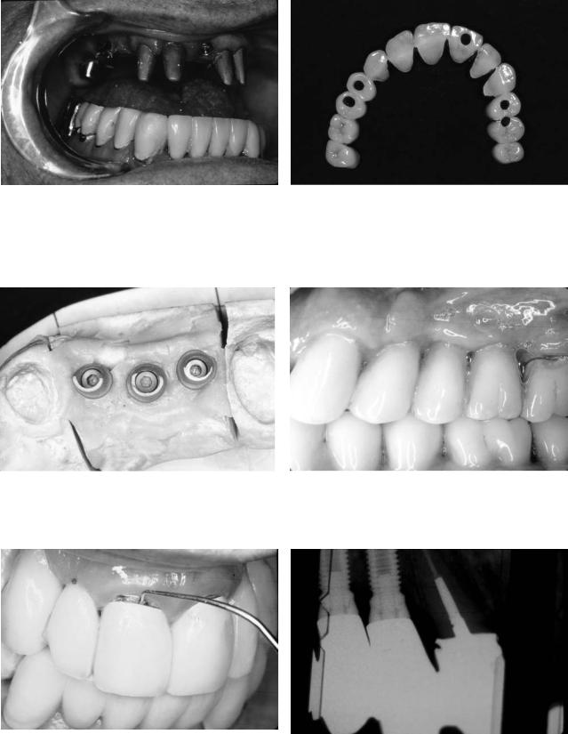
Implants can be joined to natural teeth with a variety of nonrigid connectors (i.e., semiprecision attachments). This arrangement minimizes the transfer of force from the movement of natural teeth in function to the implant component of the prosthesis. The female portion of the attachment is placed in the tooth section, and the male in the implant section. This allows depression of the natural teeth during functional loading without direct force transfer to the implants. Nonrigid attachments also permit retrievability of implant-borne segments (Figure 21A.20). This technique sometimes has complications with natural tooth intrusion.
Implants can be rigidly joined to natural teeth while maintaining retrievability. Teeth can be prepared to receive telescopic copings, which are permanently cemented. The final prosthesis is seated over the copings and implant abutments. Retention to the implant portion can be accomplished with screws or temporary cement, while the tooth component is retained with temporary cement (Figure 21A.21). Implants can also be joined to natural tooth in a nonretrievable format. When there are many more teeth than implants, it may not justify overcopings and a retrievable case. A direct cementation to the natural teeth and implants can be performed.
Nonrigid attachment and telescopic cases can become complex and expensive, and they require additional reduction of tooth structure.
There is no clear concensus regarding the proper management of the tooth–implant connection. It is generally felt that implant-supported prostheses should be freestanding whenever possible (Figure 21A.22a,b).
Abutment Intrusion
Ericsson et al.96 observed tooth abutment intrusion when nonrigidly connected to an implant. Reider and Parel102 and others have also reported this finding. English103 proposes several possible etiologies for this phenomenon (Figure 21A.23a,b). To date, the cause remains a mystery. Intrusion can be prevented by placing a U-shaped pin between the male and female portions of semiprecision attachments while preserving some resiliency. When implants are rigidly connected to natural teeth that have telescopic copings, placement of hori-
b zontal screws through the bridge into the overcopings will
FIGURE 21A.20 (a,b) Nonrigid attachment of implants to natural teeth. help prevent root intrusion while maintaining retrievability.
21A. Prosthodontic Considerations in Dental Implant Restoration |
249 |
a |
b |
FIGURE 21A.21 (a) Maxillary implants and natural teeth with copings. Telescopic copings on natural teeth allow retrievability while minimizing potential for decay. (b) Prosthesis with screw access channels.
a |
b |
FIGURE 21A.22 (a) Custom abutments on implant lab analogs with triad effect. (b) Splinted implants are freestanding and not connected to adjacent reconstruction of the natural teeth.
b
a
FIGURE 21A.23 (a) Intrusion of natural tooth with overcoping (part of full arch implants/natural tooth reconstruction). (b) Radiograph: misfit of coping and bridge due to intrusion.
250 |
J.H. Abjanich and I.H. Orenstein |
From the time of implant placement, the restorative dentist |
21A.24). The surgeon should select the longest implant that |
plays a critical role in assisting with the osseointegration |
the site will allow. The implant must have an antirotational |
process. The patient is provided with a temporary restoration |
mechanism. The surgical stent will help the surgeon properly |
that was made prior to surgery. If the prosthesis is removable, |
direct the fixture. |
there should be maximum soft tissue coverage and vertical |
Faciolingual orientation of the implant is largely depen- |
stops on teeth to prevent it from settling onto the implant sites. |
dent on the mode of prosthetic connection to be used in the |
The undersurface of the prosthesis should be relieved and in |
final restoration. Optimal esthetics and tissue emergence is |
some cases relined with tissue conditioner in the areas of fix- |
often achieved with a screwor cement-retained prosthesis on |
ture placement to prevent micromovement. Sometimes ex- |
a custom abutment. |
traction of hopeless teeth adjacent to the implant sites can be |
When screw retention is chosen, the fixture should be di- |
delayed, and they can be used to support the temporary |
rected for the access opening to coincide with the cingulum |
restoration. |
region or central fossa. Labial ridge-lapping may be neces- |
Impressions of the implant bodies (or abutments if placed |
sary to achieve proper contours of anterior teeth (Figure |
at the time of uncovering) and opposing arch can be taken |
21A.25). |
and poured at or soon after uncovering. A bite registration is |
Cemented prostheses eliminate the cosmetic and surgical |
performed. These models can be useful in a variety of ways. |
restrictions created by the screw access chamber. Often in the |
A fixed or removable temporary prosthesis as previously de- |
anterior region, the surgeon can position the implant slightly |
scribed can be made at this early stage. These “study mod- |
labially to more closely coincide with the long axis of a tooth |
els” can aid in abutment selection. A custom tray can be made |
root and potentiate a natural emergence angle. (N.B.: Exces- |
for the final impression to be taken when the tissues have |
sive labial implant positioning can result in irreversible aes- |
healed. If a temporary prosthesis will not be worn, the sur- |
thetic and functional compromise. When in doubt, it is best |
geon and restorative dentist must confirm that the healing |
to err on the side of lingual implant placement.) |
abutment or permanent abutment is not contacting the op- |
When there is collapse of the facial plate, soft and/or hard |
posing dentition as this could induce implant overload and |
tissue augmentation should be considered. |
failure. |
Apicocoronal implant positioning will affect the emergence |
|
profile of the tooth being replaced. As a general rule, the crest |
Single Tooth Restorations |
of the fixture should be located 2 to 4 mm apical to the ce- |
mentoenamel junction of the adjacent dentition110 (Figure |
|
|
21A.26), thereby permitting the replacement to emerge from |
Osseointegrated implants have been successfully used to re- |
under the gingiva at a width that corresponds to that of a nat- |
place a single missing tooth. Jemt and Pettersson104 reported |
ural tooth. When recession is present, the fixture should be |
a 98.5% cumulative implant success rate over a 3-year fol- |
placed 2 to 4 mm apical to the marginal gingiva unless the |
low-up period. Similar findings have been cited by Schmitt |
lip will conceal the neck of the restoration and the result will |
and Zarb105 and Laney et al.106 |
be consistent with the patient’s expectations. Emergence an- |
A single implant-supported tooth may be indicated to ad- |
gle is also affected by implant width. Narrow implants exist |
dress a variety of situations.107–109 Patients are often reluc- |
that may be employed to replace narrow teeth (i.e., lower in- |
tant to have adjacent intact dentition or existing bridgework |
cisors). They may also be used in ridges that are knife-edged |
disturbed for conventional crown and bridge procedures. |
as a result of bone resorption (when bone augmentation will |
Young individuals with large pulp horns on adjacent teeth are |
not be performed). Wider teeth require more apical position- |
at an increased risk of pulp exposure. A single tooth implant |
ing of narrow fixtures. Wide bony beds that will support larger |
supported restoration may be used to fill a pontic space that |
teeth may lend themselves to the use of wide-diameter |
is larger than the tooth being replaced. It may provide a sim- |
implants. |
ple solution in the presence of short teeth with a close bite. |
Mesiodistal orientation of the implant is again dependent |
One posterior implant-supported tooth may be all that is nec- |
on the prosthetic tooth position and will impact on proximal |
essary when a posterior cantilever or conventional partial den- |
contours and recreation of natural papillae. Placement should |
ture will not suffice. |
generally coincide with the mesiodistal midline of the re- |
Single tooth replacement requires precise treatment plan- |
placement tooth. |
ning and execution. A stent with opaque markers can be worn |
Access for implant uncovering can impact on final gingi- |
during CT scanning to accurately relate the remaining bone |
val contours. Vertical incisions that bisect interproximal |
to the contours of the proposed restoration. The template also |
papillae are less likely to produce papillary blunting with un- |
relates final tooth position to the remaining soft tissues and |
sightly open triangular spaces. “Cookie-cutter-type” tissue |
can aid in determining when hard and/or soft tissue augmen- |
punches sacrifice keratinized tissue and should not be used. |
tation should be performed. Hardand soft tissue augmenta- |
Stage-two surgery provides an opportunity to perform plastic |
tion procedures often coupled with barrier membrane tech- |
procedures that augment keratinized tissue and reshape gin- |
niques often permit more optimal implant placement (Figure |
gival architecture as needed to optimize aesthetics. |
21A. Prosthodontic Considerations in Dental Implant Restoration |
251 |
a |
b |
c |
d |
|
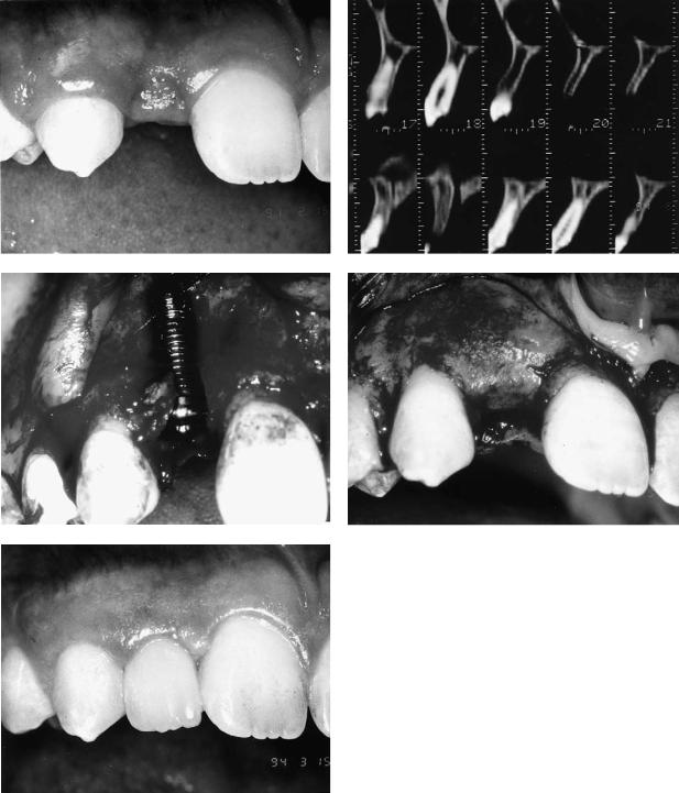
FIGURE 21A.24 (a) Congenitally missing maxillary lateral incisor site |
|
with advanced bone resorption. (b) Reformatted CT scan confirms |
|
thin labiolingual width. (c) Fixture at placement. Site was grafted |
e |
and barrier membrane placed. (d) Site at uncovering. (e) Final sin- |
gle tooth restoration. (Courtesy of Dr. Richard H. Shanaman) |
252 |
J.H. Abjanich and I.H. Orenstein |
a |
b |
FIGURE 21A.25 (a,b) Maxillary anterior implant supported fixed bridge necessitating ridge lap.
Abutment selection was discussed earlier. The single tooth abutmentmustbeantirotational.Lazarra111 introducedtheEmergence Profile System (Implant Innovations, Inc., Palm Beach Garden, FL, USA) that permits selection of a healing abutment that gradually widens from the implant coronally (Figure 21A.27). The permanent Emergence Profile abutment is selected and placed after tissue healing is complete and the final impression is taken using copings that conform to the gingival taper. Good access to the implant and abutment is maintained with less tissue impingement during prosthodontic procedures.
When aesthetic control of gingival contours must be maximized (i.e., anterior single tooth replacement with a high lip line), a custom healing abutment can be made. Upon implant insertion at stage-one surgery, a fixture impression coping is placed and an impression made. The impression and coping are removed, the cover-screw secured, and the surgery completed. An implant analog is attached to the impression coping and a model is fabricated that relates the implant to the
remaining dentition. A temporary crown that closely resembles the final restoration is produced which is inserted at the time of implant uncovering.
The implant team will often have to decide whether to place an implant immediately after tooth extraction or to allow time for healing to take place. Immediate fixture placement following extraction was first advocated by Barzilay and colleagues.112 Facial bone resorption is kept to a minimum, and the extraction socket may help with mesiodistal implant orientation (avoiding adjacent roots). The patient’s waiting period for the final prosthesis is reduced. Immediate treatment presents several potential problems. Implants should not be placed in the presence of acute infection. Primary stability of the implant is desirable and is sometimes difficult to achieve when the socket is wider than the implant. Primary soft tissue closure can be difficult to achieve and may necessitate coronal flap mobilization with resultant reduction of keratinized tissue. Bone augmentation coupled with barrier mem-
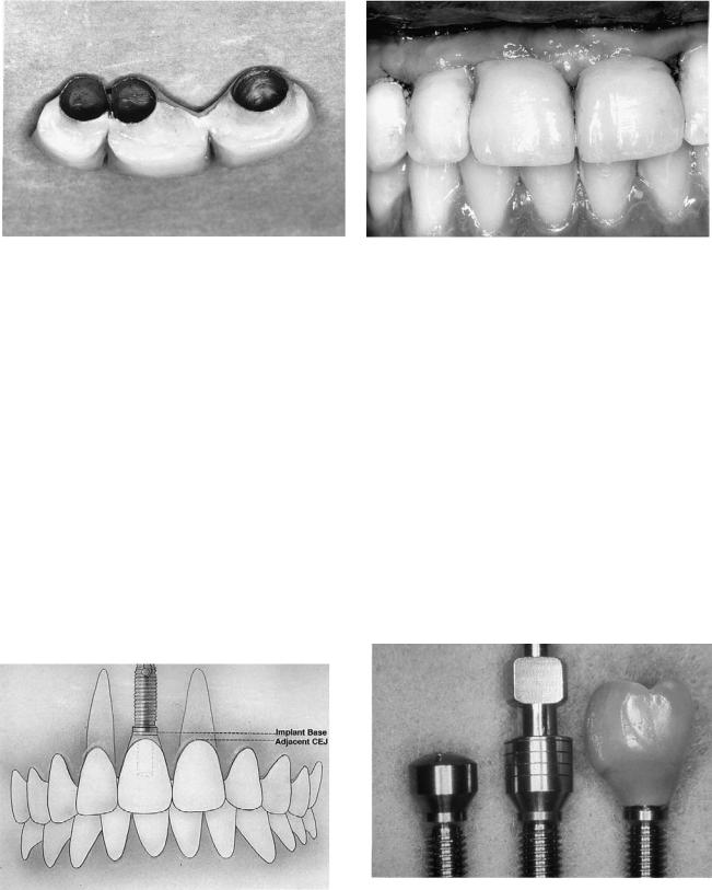
FIGURE 21A.26 Generally the implant base should be placed 2 to 4 mm apical to the adjacent gingival margin. (From Parel and Sullivan,47 by permission of Taylor Publishing Co., Dallas, TX, USA)
FIGURE 21A.27 Implant Innovations Inc. Emergence Profile System. From left to right: healing abutment, impression coping, final restoration. (Courtesy of Implant Innovations Inc., Palm Beach Gardens, FL, USA)
21A. Prosthodontic Considerations in Dental Implant Restoration
brane techniques may be indicated. Tarnow and Fletcher113 suggest allowing the extraction socket to heal for 8 to 10 weeks prior to fixture placement. This facilitates primary soft tissue closure without sacrificing keratinized tissue. The only disadvantage is the potential for osseous resorption during the 8- to 10-week waiting period. Langer114 has suggested cutting a hopeless tooth to the osseous crest and allowing tissue overgrowth for 3 to 4 weeks. The hopeless root is then extracted. The additional soft tissue will provide better closure during implant placement. Mensdorff-Pouilly115 and colleagues compared immediate and primary immediate (placed 6 to 8 weeks postextraction) implants. The immediate implants showed a tendency toward deeper pocket formation and an increased frequency of membrane dehiscence. This may reflect the poorer quality of soft tissue coverage. Nevins and Mellonig116 advocate a staged approach when immediate and primary immediate implant placement is not possible. When indicated, the alveolar bone is initially reconstructed with guided tissue regeneration in combination with bone grafts. After a 10-month waiting period the fixtures are placed.
The implant team must pay particular attention to biomechanics when replacing single teeth. Contacts should be light in centric and absent in lateral excursions. Fixtures should be directed to receive axial loads whenever possible and particularly in the posterior region where occlusal forces are greater. Single tooth restorations are particularly subject to rotational forces around the long axis of the implant. It is sometimes possible to replace a single missing molar with two implants117 to minimize these rotational forces and provide additional support for the replacement tooth. When bone volume permits, a wide-diameter implant should be used. This will allow occlusal forces between the cusp tips to be directed over the implant body.
Several potential noteworthy complications are associated with the single tooth replacement. The most common problem reported by Jemt and Pettersson104 and others is loosening and fatigue of the abutment screw, which sometimes leads to fistulae and gingival hyperplasia. Possible causes include rotational forces and inaccurate fit of custom cast abutments at the interface with the implant head. Screw loosening decreases over time. Nobel Biocare’s CeraOne® (Nobel Biocare, USA, Inc., Yorba Linda, CA) system incorporates a new gold-palladium screw that is tightened with a torque-con- troller to 32 Ncm and is reported by Boudrias118 to show no clinical signs of loosening. Other complications include devitalization of adjacent roots, implant failure, bone loss, or both; loss of gingival height and papillae; and poor aesthetics resulting from improperly directed implants.
Complications
Implant Failure
Long-term osseointegration has been documented to be 93% for individual implants in the anterior mandible and 84% in
253
the maxilla.3 The causes for decreased maxillary implant success are probably multifactorial. Maxillary bone quality is often poorer than its mandibular counterpart. Anatomic obstacles (i.e., maxillary sinus, nasal fossa) coupled with decreased bone volume secondary to resorption often call for the use of short implants, which Jemt76 has shown to have a higher rate of failure than longer implants in the maxilla. Short implants are usually placed in regions of significant resorption, which results in a high crown-to-implant ratio. Aesthetics, phonetics, occlusion, and lip and cheek support often necessitate significant facial positioning of maxillary fixed prostheses. The resulting cantilever can produce off-axis forces and difficulty with hygiene due to excessive ridge-lapping. The overall effect is a lower rate of implant success observed in the maxilla. It therefore becomes prudent to always inform the patient that it may be necessary to employ a secondary treatment plan in the event of implant failure. A patient should never be promised a fixed prosthesis. This is particularly important when bone grafting procedures are performed, which make it difficult to accurately predict final fixture location.
Several prosthetic factors can contribute to implant bone loss and failure. Achieving and maintaining osseointegration begins at the treatment-planning stage. Anticipated prosthesis design must take into consideration adequate implant support and distribution. A surgical template helps assure proper fixture orientation. The temporary prosthesis should be adequately relieved to prevent micromovement of fixtures during the integrationphase.Uponuncovering,healingorpermanentabutments should not contact opposing dentition and temporization that promotes progressive loading as previously discussed should be considered. The final prosthesis should fit passively and the occlusion refined. The design should permit full hygiene access to all implant abutment and prosthesis surfaces.
The impact of parafunctional habits should be minimized by providing additional implant support where possible. The prosthesis should be durable, and a night guard should be considered.
Fixture failure is most obviously evidenced by mobility. This may not be apparent if a splinted prosthesis is not routinely removed at recall visits. Radiographic evidence of a mobile fixture often reveals a lucent area between the implant and surrounding bone. The gingival collar may be inflamed and hyperplastic. No attempt should be made to save mobile implants. They should be removed as soon as possible and the remaining prosthesis evaluated for adequate support and possible modification or removal.
The potential for implant failure may be evidenced in more subtle ways. Maximal crestal bone loss should be 1.5 mm within the first year after surgery and 0.1 mm every year thereafter.119 When bone loss appears to be excessive, it behooves the implant team to attempt to identify the problem and intervene expeditiously.
The gingival tissues may often provide the earliest evidence of an ailing implant in the forms of inflammation, hyperplasia, pocketing, fistula formation, and recession. Implant overload may be manifest by pocket formation in the absence of
254 |
J.H. Abjanich and I.H. Orenstein |
|
gingival inflammation. Loosening of abutment screws may |
and/or fracture. A fractured screw indicates biomechanical |
|
cause hyperplasia and fistula formation as observed by Jemt |
breakdown, and its etiology must be determined to prevent |
|
et al.120 for single tooth restorations. Plaque retention may |
greater adverse sequelae. |
|
cause gingival inflammation, and the patient must be en- |
Removal of broken screws can at times present a challenge. |
|
couraged to actively participate in a comprehensive hygiene |
If the gold screw fractures so that a portion remains inside the |
|
program. Despite the patient’s best intentions, several obsta- |
abutment screw and it cannot be readily retrieved, the easiest |
|
cles may preclude optimal hygiene performance. The restora- |
solution is to remove and replace the abutment screw with a |
|
tion may not permit full access to the prosthesis-abutment- |
new one. The greater problem arises when the abutment screw |
|
implant interfaces. Titanium abutments may scratch easily |
fractures within the screw channel of the implant body and can- |
|
and encourage plaque adherence. Exposed hydroxylapatite, |
not be reached with a narrow forceps. When the abutment screw |
|
fixture threads, or plasma-sprayed implant surfaces may sim- |
fractures, it almost always loosens first. The section remaining |
|
ilarly attract plaque. |
in the implant can usually be teased out. An explorer tip can |
|
|
be placed near the edge of the screw and rotated counter- |
|
Implant Fracture |
clockwise. If this is not successful, another method of retrieval |
|
calls for placing a small eccentric notch into the superior por- |
||
|
||
Naert et al.121 observed a 0.5% rate of fixture fracture when |
tion of the screw fragment with a quarter-round bur being care- |
|
supporting a complete fixed prosthesis. Fracture of implants |
ful not to damage the internal threads of the screw channel. An |
|
is directly attributable to biomechanical overload and can oc- |
explorer tip is then inserted into the notch, and the fragment is |
|
cur with any prosthesis type. The etiology should be sought |
backed out. Implant Innovations, Inc. (Palm Beach Gardens, |
|
to minimize recurrence of this problem. The fractured frag- |
FL, USA) manufactures a screw-removing system for Bråne- |
|
ment need not be removed if it is free of pathology and if the |
mark and Brånemark-compatible implants that protects the in- |
|
site is not needed for fixture replacement. If the implant frac- |
ternal threads of the fixture from damage during retrieval. Ul- |
|
tures at the neck, it may still be usable by adapting a UCLA- |
trasonic scalers are also useful in rotating fractured abutment |
|
type abutment to the fracture interface with Duralay resin (Re- |
screws out. |
|
liance Dental Mfg. Co., Worth, IL, USA) and casting a custom |
|
|
abutment. Implant trephines can be employed to assist in re- |
Stripped Threads |
|
moval of unwanted fractured segments. |
|
|
|
Clinicians should be careful to avoid stripping the internal fix- |
|
Loose and Fractured Screws |
ture threads. This problem can occur when engaging the fix- |
|
ture mount during implant surgery or when connecting abut- |
||
|
||
Loosening of abutment and prosthetic retaining screws is a |
ments or fixture impression copings. All connections should |
|
common observation. There are several possible etiologies for |
be smooth with no binding. Proper use of torque-control de- |
|
this finding, including inadequate tightening of screws, bio- |
vices assures appropriate tightening of screws. Nonpassive |
|
mechanical overload, and poor fit of the prosthesis. Nobel Bio- |
seating of prostheses that are screw-retained directly to the |
|
care, USA, Inc. (Yorba Linda, CA) developed a torque con- |
implant heads may cause thread damage. Some prostheses are |
|
trol device that can be used to tighten Brånemark-implant |
cemented to abutments that are screw-retained to the implant. |
|
component screws with a precise amount of force. The gold |
If an abutment screw loosens, the prosthesis must often be re- |
|
retaining screw and abutment screw receive 10 Ncm and 20 |
moved to reaccess the loose screw. The internal implant |
|
Ncm of torque, respectively. Nobel Biocare acknowledges the |
threads are particularly vulnerable to damage when the pros- |
|
increased likelihood of screw loosening encountered with sin- |
thesis is being tapped off. |
|
gle tooth restorations and has developed a gold-palladium |
Implant Innovations, Inc. (Palm Beach Gardens, FL, USA) |
|
screw for their CeraOne® single tooth abutment that is tight- |
manufactures a tapping tool designed to rethread the damaged |
|
ened to 32 Ncm. Paragon (Paragon Implant Company, Encino, |
internal screw channel of Brånemark and Brånemark-com- |
|
CA, USA) developed an implant design with an internal hexa- |
patible implants. It is easy to use and provides precise tap- |
|
gon that joins an abutment that has a 1° tapered external hexa- |
ping within minutes. |
|
gon (Taper-Lock mating system). The resulting antirotational |
|
|
frictional fit is said to reduce the frequency of abutment screw |
Prosthodontic Solutions for Compromised |
|
loosening. Some implant systems utilize a Morse taper design |
Implant Placement |
|
to establish a secure implant abutment connection. |
|
|
Fracture of abutment and prosthetic retaining screws can |
Poor implant position creates an all-too-common dilemma. Im- |
|
occur for any of the same reasons as screw loosening. Wal- |
plant position should incorporate the biomechanical, functional, |
|
ton et al.122 found replacement of fractured gold screws to be |
and aesthetic principles previously discussed. This is best |
|
the most common repair for fixed implant-supported pros- |
achieved through proper planning and stent fabrication. The se- |
|
theses. Nobel Biocare designed the gold retaining screw to be |
verely off-angled implant often requires complex management. |
|
the “weak link” to protect the implant body from overload |
The need for coordinated planning of implant placement be- |
21A. Prosthodontic Considerations in Dental Implant Restoration
tween the surgeon and restorative dentist cannot be overstated. Despite careful communication and proper stent use, several anatomic limitations will restrict ideal positioning. The nasal fossa, maxillary sinus, incisive canal, and inferior alveolar nerve will often prevent optimal placement. Bony undercuts can result in flared maxillary fixtures to avoid apical perforations without bone grafting. Mandibular posterior implants may require a lingual tilt to avoid the retromylohyoid fossa. Advanced ridge resorption in the maxilla may yield palatally positioned implants. The surgeon’s attempt to engage cortical plates may yield a less favorable emergence position. Residual ridge height, width, shape, and relationship to the opposing arch can compromise fixture orientation. Bone grafting procedures that improve implant position, length, and distribution should be considered on a case by case basis. Only with optimal placement can the ultimate restorative result be achieved. The restorative dentist may employ several strategies when restoring fixtures with compromised orientation.
Prefabricated angled abutments are available with a variety of tilts. They are usually connected directly to the fixture. Depending upon the abutment type, the prosthesis can be either screwor cement-retained.
Custom abutments allow the restorative dentist to optimize control of orientation, emergence profile, and retention. A plastic or gold UCLA-type pattern is custom waxed and cast, enabling one to control angulation of the implant post. Allplastic patterns should be machined with a lapping tool after casting to ensure precise fit to the implant. Patterns should be cast in an alloy with less than 9% silver. Metals with high silver content deform more easily, which can accelerate wear at the screw and implant interfaces.123 Custom abutments are particularly useful in the maxillary anterior region where, due to ridge inclination, screw-access holes would often exit the labial of the tooth, severely compromising esthetics.
Mesostructures can be fabricated on some or all of a series of abutments. This substructure is usually screw-retained and houses the overlying suprastructure. The suprastructure will be veneered with the aesthetic tooth material (i.e., porcelain, denture teeth, or composite resin). Mesostructures offer an advantage when porcelain fused to metal restorations are used. After firing large sections of porcelain, distortion of the substructure can occur. Since the mesostructure is not veneered, its fit to the implants would not be altered and would not yield additional stress after ceramic firing. Mesostructures should be reserved for situations in which severely misaligned implants cannot be managed by more conventional means. These prostheses greatly increase cost and complexity, and they can be bulky. Suprastructures that are cement retained can still be retrievable when a provisional luting agent is used.
Tube and screw attachments are prefabricated with a gold alloy. The female portion can be incorporated into the mesostructure and the male into the suprastructure, yielding a retrievable screw-retained prosthesis. This can be utilized with severely off-angled implants (Figure 21A.28).
Lingual positioned implants are most ideally restored with
255
a screw-retained prosthesis (refer to Figure 21A.6a,b). The framework must be designed to be flush with the ridge at the interface of the screw access chamber and the mucosal surface in order to avoid tongue impingement and altered phonetics. If sufficient countersinking has not been performed with implant heads close to the marginal gingiva, framework connection will likely be directly to the implants to further minimize bulk. These frameworks can be extended labially to support veneering materials. Angulated or custom abutments are less than ideal in these cases since the resulting prosthesis may be too bulky.
Interproximal positioning of implants can cause problems in visible areas where aesthetics is important. This is particularly relevant to cases with minimal resorption in conjunction with a high lip line. Fixtures that emerge between teeth can be masked with a flange where necessary (using pink porcelain or acrylic). If sufficient redundancy exists, the problematic fixture may be buried and not used. A flange is never a good substitute for proper mesiodistal implant positioning.
Interproximal positioning of fixtures often occurs in the posterior mandible. In an attempt to avoid the mental foramen on its distal side, the surgeon will often place the implant between the second premolar and first molar position. This problem may repeat itself as subsequent posterior implants are placed. In some instances it may be better to keep the first site distal to the mental foramen vacant to avoid this aesthetic problem.
Esthetic Complications
Implant prostheses can be host to a variety of esthetic complications. The complete maxillary fixed prosthesis as originally described by Brånemark124 was designed to stand 1 to 2 mm from the gingiva to facilitate oral hygiene procedures. Unfortunately, many patients experienced difficulty with phonetics as air escaped under the prosthesis. For some patients, this problem abates over time as the upper lip adapts to limit excessive air flow by creating a seal against the prosthesis. For others the problem continues, and a removable labial flange can be fabricated from silicone or resin to help correct phonetic and aesthetic deficiencies. Unfortunately, the patient expecting a fixed prosthesis ends up with “removable gingiva.” These veneers tear easily, attract plaque, and require frequent remakes.125 For patients with a high smile line, minimal maxillary ridge resorption, or both, implants in the incisor region should precisely correspond to the final tooth positions. If this cannot be achieved, one might consider not placing implants in this area. Short maxillary posterior cantilevers may present aesthetic problems if the buccal corridor is not adequately supported. For patients with severe maxillary and/or mandibular ridge resorption, complete fixed prostheses may not be capable of adequately replacing missing hard and soft tissue, resulting in deficient facial support. This problem can be avoided by fabricating a diagnostic setup of teeth to help choose between a fixed prosthesis and an over-

256 |
J.H. Abjanich and I.H. Orenstein |
a |
b |
c
FIGURE 21A.28 Mesostructure prosthesis with tube and screw retention. (a) Substructure: retained to implant analogues (1); tube and screw attachments (2) Implant screws. (b) Substructure (top) and
denture design. If the tooth position does not approximate the ridge, a removable design may be appropriate. When fabricating a fixed prosthesis with acrylic resin and denture teeth, it is necessary to opaque the metal substructure when the acrylic is less than 2 mm thick.
Removable overdentures present with far fewer aesthetic complications. When vertical space is limited, retention clips may create bulking of acrylic in areas that are either visible or annoying to the tongue. This problem may be minimized by performing selective alveoplasty at the time of surgery and choosing a retentive mechanism with reduced vertical and/or horizontal dimensions. Alternatively, a fixed prosthesis may be the treatment of choice in jaws with minimal resorption and limited intermaxillary space.
The single tooth replacement is most vulnerable to aesthetic complications that have been detailed previously.
Patient Expectations
A potentially serious complication associated with implant therapy is the development of false expectations on the part
suprastructure retained by tube and screw attachments (bottom). (c) Final prosthesis.
of the patient. The fully edentulous patient may accept implant treatment to construct a fixed prosthesis only to realize that the treatment plan must be changed later on. The removable prosthesis should not be considered inferior. Each has its advantages and limitations as previously described.
Failure of Restorative Materials
Several potential complications exist concerning the choice of restorative materials. Johansson and Palmqvist126 found fractures of acrylic suprastructure resin or artificial teeth in 22% of full-arch implant-supported fixed prostheses during an observation period of 3 to 8 years. Jemt76 found this problem to be most prevalent in the maxillary arch. Acrylic artificial teeth can wear over time with resulting occlusal changes. Denture teeth also require more room for placement than porcelain and will fracture if made too thin. Porcelain, on the other hand, shrinks on firing and can deform the underlying metal with a resulting loss of passivity of fit.
Walton and MacEntee127 noticed an increased rate of repairs of complete dentures opposing implant-supported pros-

21A. Prosthodontic Considerations in Dental Implant Restoration
theses. This potential problem can be minimized by reinforcing such dentures with a metal framework. These investigators also observed that removable implant prostheses require three times as many adjustments and two times as many repairs as fixed implant-supported prostheses. The most common repair needed for removable prostheses were associated with retention clips, whereas the most common repair for fixed prostheses involved fracture of gold screws.
Complete implant-supported fixed prostheses are vulnerable to framework fracture at the cantilever extension joints. These regions should be designed with adequate bulk to resist biomechanical forces.
Maintenance
As with conventional prosthodontic rehabilitation, long-term success with implant-supported restorations depends on patient compliance with maintenance procedures. The impact of plaque and calculus formation upon implant surfaces is currently under investigation. George et al.128 found a correlation between implants with gingival inflammation and the presence of pathogens associated with periodontitis. Maintenance of a clean permucosal environment begins at stage-two uncovering. Upon suture removal or initial tissue healing the surgeon will instruct the patient to gently brush the healing or permanent abutments. Access for patient hygiene procedures is optimal at this point. Sulcular areas lacking keratinized mucosa tend to be more sensitive, and the dentist should confirm that these sites are not being avoided. Abutments should not be occluding against the opposing dentition and temporary prostheses should be appropriately relieved, relined with resilient material, or both to prevent implant overload. Temporary removable prostheses should be cleaned by
257
the patient regularly. Temporary fixed restorations should be designed to mimic the final prosthesis, giving the patient an opportunity to develop oral hygiene skills at this early phase.
Upon delivery of the final prosthesis, recall intervals should be established appropriate to the patient’s needs. The patient, hygienist, and dentist must all use instruments that will not scratch abutment surfaces. Plastic (Nobel Biocare, USA, Inc., Yorba Linda, CA), gold-plated (Hu-Freidy, Chicago, IL, USA), and graphite (Premier Dental Products Co., Norristown, PA, USA) scalers as well as plastic pressure-sensitive periodontal probes (e.g., Sensor Probe, Pro-Dentec, Batesville, AR, USA) have been developed specifically for implant maintenance procedures. SofScale Calculus Scaling Gel (Ash/Dentsply International, York, PA, USA) softens calculus, thereby facilitating the ease of its removal. At home, the patient can incorporate conventional tooth brushing and flossing as well as heavier flosses (e.g., Oral-B Super Floss, Oral B Laboratories, Redwood City, CA, USA) and Butler Implant Floss (John O. Butler Company, Chicago, IL, USA) and end-tufted brushes (e.g., Lactona Double-End Interdental Brush, Lactona Corporation, Montgomeryville, PA, USA) into the daily routine. (Figure 21A.29). Electric mechanical brushes may be recommended by some dentists and/or preferred by patients.
The use of chlorhexidine gluconate (Peridex, Procter and Gamble, Cincinnati, OH, USA) concurrent with various phases of implant therapy and maintenance is being investigated and has been shown to reduce the rate of infectious complications to stage two uncovering (Dental Implant Clinical Research Group, Ann Arbor, MI, USA). The dentist may elect to take advantage of the retrievable nature of most implant prostheses. Removing the restoration at appropriate intervals allows the dentist and hygienist to visualize areas of plaque and calculus accumulation. This is particularly appro-
FIGURE 21A.29 Oral hygiene aids from left to right: Interdental brush (Lactona Corp. Montgomeryville, PA, USA); SofScale Calculus Scaling Gel (Ash/Dentsply International, York, PA, USA); graphite scaler (Premier Dental Products Co., Norristown, PA, USA); Sensor Probe (Pro-Dentec, Batesville, AR, USA); Oral-B Super Floss (Oral-B Laboratories, Redwood City, CA, USA).
258
priate for restorations that require ridge-lapping, where oral hygiene measures are more complex. Implants can be checked for mobility and the gingival areas readily examined and pockets probed. Secure abutment connections can be verified. Radiographs should be taken to monitor crestal bone levels and confirm the integrity of the implant-bone interface. Threads on Brånemark implants are machined at 0.5-mm intervals and can be used to gauge bone loss.129
The prosthesis should be regularly examined for evidence of bruxism and occlusal changes that can lead to biomechanical overload. Acrylic and porcelain fractures are more readily repaired when prostheses are retrievable. Overdenture retentive elements should be adjusted and replaced when necessary. Over time, hard and soft tissues resorb from beneath overdentures that are fixtureor tissue-supported, making the implant components increasingly vulnerable to biomechanical overload. Such prostheses should be relined as needed and the retentive elements carefully replaced incorporating techniques that maintain resiliency of the prosthesis when indicated.
Periotest was discussed earlier as a tool that may help assess osseointegration. The same instrument may be employed during maintenance visits to confirm integration and to observe changes in bone density surrounding implants. It is possible that the earliest signs of implant overload may be captured, thereby permitting immediate intervention. The usefulness of Periotest for implant therapy is currently being investigated (Dental Implant Clinical Research Group, Ann Arbor, MI).
References
1.Brånemark P-I, Zarb GA, Albrektsson T. Tissue-Integrated Prostheses Osseointegration in Clinical Dentistry. Chicago: Quintessence Publishing Co. Inc.; 1985.
2.Brånemark P-I, Hansson BO, Adell R, Breine U, Lindstrom J, Hallen O, Ohman A, et al. Osseointegrated implants in the treatment of the edentulous jaw. Experience from a 10-year period. Scand J Plast Reconstr Surg. Suppl 1977;16:1–132.
3.Adell R, Lekholm U, Rockler B, et al. A fifteen year study of osseointegrated implants in the treatment of the edentulous jaw. Int J Oral Surg. 1981;6:387–416.
4.Monson ML. Diagnostic and surgical guides for placement of dental implants. J Oral Maxillofac Surg. 1994;52:642–645.
5.Orenstein IH. The surgical template: a prescription for implant success. Implant Dent. 1992;1:182–184.
6.Weinberg LA. CT scan as a radiologic data base for optimum implant orientation. J Prosthet Dent. 1993;69:381–385.
7.Lekholm U, Zarb GA. Patient selection and preparation. In: Branemark P-I, Zarb GA, Albrektsson T, eds. TissueIntegrated Prostheses Osseointegration in Clinical Dentistry.
Chicago: Quintessence Publishing Co. Inc.; 1985:199–209.
8.Misch CE, Judy KW. Classification of partially edentulous arches for implant dentistry. Int J Oral Implantol. 1987;4:7–13.
9.Jensen O. Site classification for the osseointegrated implant. J Prosthet Dent. 1989;61:228–234.
10.Misch CE. Density of bone: effect on treatment planning, sur-
J.H. Abjanich and I.H. Orenstein
gical approach, and healing. In: Misch CE, ed. Contemporary Implant Dentistry. St Louis: Mosby Year Book, Inc.; 1993: 469–485.
11.Jaffin RA, Berman CL. The excessive loss of Brånemark fixtures in type IV bone: a 5-year analysis. J Periodontol. 1991;62:2–4.
12.Orenstein IH, Synan WJ, Truhlar RS, et al. Bone quality in patients receiving endosseous dental implants: DICRG interim report no. 1. Implant Dent. 1994;3:90–94.
13.Bidez MW, Misch CE. Force transfer in implant dentistry: basic concepts and principles. J Oral Implantol. 1992;18:264– 274.
14.Aloia JF, Cohn SH, Ostuni Ja, et al. Prevention of involutional bone loss by exercise. Ann Intern Med. 1978;89:356–358.
15.Misch CE. Progressive bone loading. In: Misch CE, ed. Contemporary Implant Dentistry. St Louis: Mosby Year Book, Inc.; 1993:623–650.
16.Misch CE. Implant success or failure: clinical assessment. In: Misch CE, ed. Contemporary Implant Dentistry. St Louis: Mosby Year Book, Inc.; 1993:29–42.
17.Jaggers A, Simons AM, Badr SE. Abutment selection for anterior single tooth replacement: a clinical report. J Prosthet Dent. 1993;69:133–135.
18.Prestipino V, Ingber A. Esthetic high strength implant abutments. Part I. J Esthetic Dent. 1993;4:29–36.
19.Prestipino V, Ingber A. Esthetic high-strength implant abutments. Part II. J Esthetic Dent. 1993;5:63–68.
20.Kvarnstrom B. Personal communication. Nobelpharma Inc., Chicago, IL. April 1995.
21.Baumgarten HS, Salama H, Nelson A. Abutment head selection as a prosthetic discipline. Compendium. 1991;12:942–947.
22.Chiche GJ, Pinault A. Considerations for fabrication of im- plant-supported posterior restorations. Int J Prosthodont. 1991;4:37–44.
23.Friedman N, Landesman HM, Wexler M. The influence of fear, anxiety, and depression on the patient’s adaptive responses to complete dentures. Part 1. J Prosthet Dent. 1987;58:687–689.
24.Davidoff SR, Steinberg MA, Halperin A. The implant-sup- ported overdenture: a practical implant-prosthetic design. Compendium. 1993;14:722–730.
25.Carlsson G, Haraldson T. Fundamental aspects of mandibular atrophy. In: Worthington P, Brånemark P-I, eds. Advanced Osseointegration Surgery: Applications in the Maxillofacial Region. Chicago: Quintessence Publishing Co. Inc.; 1992;109– 118.
26.Carlsson GE, Persson G. Morphologic changes of the mandible after extraction and wearing of dentures: a longitudinal, clinical and x-ray cephalometric study covering 5 years. Odontol Rev. 1967;18:27–54.
27.Hickey JC, Zarb GA. The edentulous state. In: Hickey JC, Zarb GA, eds. Boucher’s Prosthodontic Treatment for Edentulous Patients. St. Louis: C.V. Mosby Co.; 1980:3–43.
28.Bahat O. Treatment planning and placement of implants in the posterior maxillae: report of 732 consecutive Nobelpharma implants. Int J Oral Maxillofac Implants. 1993;8:151–161.
29.Watson RM, Davis DM, Forman GH, et al. Considerations in design and fabrication of maxillary implant-supported prostheses. Int J Prosthodont. 1991;4:232–239.
30. DeBoer J. Edentulous implants: overdenture versus fixed. J Prosthet Dent. 1993;69:386–390.
21A. Prosthodontic Considerations in Dental Implant Restoration
31.Parel SM. Implants and overdentures; the osseointegrated approach with conventional and compromised applications. Int J Oral Maxillofac Implants. 1986;1:93–99.
32.Adell R, Eriksson B, Lekholm U, et al. A long-term follow-up study of osseointegrated implants in the treatment of totally edentulous jaws. Int J Oral Maxillofac Implants. 1990;5:347– 359.
33.Weinberg LA, Kruger B. Biomechanical considerations when combining tooth-supported and implant-supported prostheses.
Oral Surg Oral Med Oral Pathol. 1994;78:22–27.
34.Carlsson L. Built-in strain and untoward forces are the inevitable companions of prosthetic misfit. Nobelpharma News. 1994;8:5.
35.Gyllenram F. Optimal clinical fit is a multi-dimensional issue.
Nobelpharma News. 1994;8:4.
36.Jemt T, Carlsson L, Boss A, et al. In vivo load measurements on osseointegrated implants supporting fixed or removable prostheses: a comparative pilot study. Int J Oral Maxillofac Implants. 1991;6:413–417.
37.Assif D, Fenton A, Zarb G, et al. Comparative accuracy of implant impression procedures. Int J Periodont Restor Dent. 1992;12:112–21.
38.Carr AB. Comparison of impression techniques for a fiveimplant mandibular model. Int J Oral and Maxillofac Implants.
1991;6:448–55.
39.Zarb GA, Jansson T. Prosthodontic procedures. In: Brånemark P-I, Zarb GA, Albrektsson T, eds. Tissue-Integrated Prosthesis Osseointegration in Clinical Dentistry. Chicago: Quintessence Publishing Co. Inc.; 1985.
40.Ivanhoe JR, Adrian ED, Krantz WA, et al. An impression technique for osseointegrated implants. J Prosthet Dent. 1991;66: 410–411.
41.Lechner S, Duckmanton N, Klineberg I. Prosthodontic procedures for implant reconstruction. 2. Post-surgical procedures. Aust Dent J. 1992;37:427–432.
42.Barrett MG, de Rijk WG, Burgess JO. The accuracy of six impression techniques for osseointegrated implants. J Prosthodont. 1993;2:75–82.
43.Humphries RM, Yaman P, Bloem TJ. The accuracy of implant master casts constructed from transfer impressions. Int J Oral Maxillofac Imp. 1990;5:331–336.
44.Goll GE. Production of accurately fitting full-arch implant frameworks. Part 1. Clinical procedures. J Prosthet Dent. 1991;66:377–384.
45.Parel SM, Sullivan DY. Esthetics and Osseointegration. Dallas: Taylor Publishing Co.; 1989.
46.Jemt T, Linden B. Fixed implant-supported prostheses with welded titanium frameworks. Int J Periodont Restor Dent. 1992;12:177–184.
47.Nadeau P. Personal communication. Nobelpharma Inc. Chicago, IL. April 1995.
48.English CE. The critical a-p spread. Implant Soc. 1990;1:2–3.
49.Hobo S, Ichida E, Garcia LT. Fully bone anchored prostheses. In: Hobo S, Ichida E, Garcia LT, eds. Osseointegration and Occlusal Rehabilitation. Tokyo: Quintessence Publishing Co. Ltd., 1989:163–186.
50.Naert I, Quirynen M, van Steenberghe D, et al. A study of 589 consecutive implants supporting complete fixed prosthesis. Part 2. Prosthetic aspects. J Prosthet Dent. 1992;68:949–956.
51.Shackleton JL, Carr L, Slabbert JC, et al. Survival of fixed im-
259
plant-supported prosthesis related to cantilever lengths. J Prosthet Dent. 1994;71:23–26.
52.Takayama H. Biomechanical considerations on osseointegrated implants. In: Hobo S, Ichida E, Garcia LT, eds. Osseointegration and Occlusal Rehabilitation. Tokyo: Quintessence Publishing Co. Ltd.; 1989:265–280.
53.Lindqvist L, Rockler B, Carlsson G. Bone resorption around fixtures in edentulous patients treated with mandibular fixed tissue-integrated prosthesis. J Prosthet Dent. 1988;59:59–63.
54.Sullivan DY. Implant restoration of the edentulous maxilla. Presented at the American College of Prosthodontists annual scientific session, New Orleans, Hyatt Regency Hotel, 3–5 November 1994.
55.White SN, Caputo AA, Anderkvist T. Effect of cantilever
|
length on stress transfer by implant-supported prostheses. |
|
J Prosthet Dent. 1994;71:493–499. |
56. |
Zarb GA, Schmitt A. The longitudinal clinical effectiveness of |
|
osseointegrated dental implants: the Toronto study. Part 3: |
|
Problems and complications encountered. J Prosthet Dent. |
|
1990;64:185–194. |
57. |
Fischman B. The rotational aspect of mandibular flexure. |
|
J Prosthet Dent. 1990;64:483–485. |
58.McCartney JW. Cantilever rests: an alternative to the unsupported distal cantilever of osseointegrated implant-supported prostheses for the edentulous mandible. J Prosthet Dent. 1992;68:817–819.
59.Skalak R. Aspects of biomechanical considerations. In: Brånemark P-I, Zarb GA, Albrektsson T, eds. Tissue-Integrated Prosthesis Osseointegration in Clinical Dentistry. Chicago: Quintessence Publishing Co. Inc.; 1985:117–128.
60.Gracis SE, Nicholls JI, Chalupnik JD, et al. Shock-absorbing behavior of five restorative materials used on implants. Int J Prosthodont. 1991;4:282–291.
61.Davis DM, Rimrott R, Zarb GA. Studies on frameworks for osseointegrated prostheses. Part 2. The effect of adding acrylic resin or porcelain to form the occlusal superstructure. Int J Oral Maxillofac Implants. 1988;3:275–280.
62.Naert I, Quirynen M, van Steenberghe D, et al. A six-year prosthodontic study of 509 consecutively inserted implants for the treatment of partial edentulism. J Prosthet Dent. 1992; 67:236–245.
63.Johns RB, Jemt T, Heath MR. A multicenter study of overdentures supported by Branemark implants. Int J Oral Maxillofac Implants. 1992;7:513–522.
64.Mericske-Stern R, Zarb GA. Overdentures: an alternative implant methodology for edentulous patients. Int J Prosthodont. 1993;6:203–208.
65.Feine JS, Maskawi K, de Grandmont P, et al. Within-subject comparisons of implant-supported mandibular prostheses: evaluation of masticatory function. J Dent Res. 1994;73: 1646–1656.
66.Pietrokovski J. The bony residual ridge in man. J Prosthet Dent. 1975;34:456–462.
67.Arbree NS, Chapman RJ. A comparison of mandibular denture base extension in conventional and implant-retained dentures. J Prosthet Dent. 1991;65:108–111.
68.Drago CJ. Tarnish and corrosion with the use of intraoral magnets. J Prosthet Dent. 1991;66:536–540.
69.Lewis S. Implant-retained overdentures. Compendium. 1993; 14:1270–1283.
260
70.Dolder EJ, Durer GT. The Bar-Joint Denture. Chicago: Quintessence Publishing Co. Inc.; 1978.
71.Davidoff SR, Steinberg MA, Halperin A. The implantsupported overdenture: a practical implant-prosthetic design. Compendium. 1993;14:722–730.
72.Naert I, Quirynen M, Hooghe M, et al. A comparative prospective study of splinted and unsplinted Brånemark implants in mandibular overdenture therapy: a preliminary report. J Prosthet Dent. 1994;71:486–492.
73.Donatsky O. Osseointegrated dental implants with ball attachments supporting overdentures in patients with mandibular alveolar ridge atrophy. Int J Oral Maxillofac Implants.
1993;8:162–166.
74.Desjardins RP. Prosthesis design for osseointegrated implants in the edentulous maxilla. Int J Oral Maxillofac Implants.
1992;7:311–320.
75.Friberg B, Jemt T, Lekholm U. Early failure in 4,641 consecutively placed Branemark dental implants. A study from stage 1 surgery to the connection of completed prostheses. Int J Oral Maxillofac Implants. 1991;6:142–146.
76.Jemt T. Failures and complications in 391 consecutively inserted fixed prostheses supported by Brånemark implants in edentulous jaws: a study of treatment from the time of prosthesis placement to the first annual checkup. Int J Oral Maxillofac Implants. 1991;6:270–276.
77.Taylor TD. Fixed implant rehabilitation for the edentulous maxilla. Int J Oral Maxillofac Implants. 1991;6:329–337.
78.Jemt T. Fixed implant-supported prostheses in the edentulous maxilla. A five-year follow-up report. Clin Oral Implants Res. 1994;5:142–147.
79.Johns RB, Jemt T, Heath MR, et al. A multicenter study of overdentures supported by Branemark implants. Int J Oral Maxillofac Implants. 1992;7:513–522.
80.Langer B. Personal communication. New York, NY. March 1995.
81.Jemt T, Book K, Linden B, et al. Failures and complications in 92 consecutively inserted overdentures supported by Branemark implants in severely resorbed edentulous maxillae: a study from prosthetic treatment to first annual check-up. Int J Oral Maxillofac Implants. 1992;7:162–167.
82.Van Roekel NB. Prosthesis fabrication using electrical discharge machining. Int J Oral Maxillofac Implants. 1992;7: 56–61.
83.Naert I, Quirynen M, van Steenberghe D, et al. A six-year prosthodontic study of 509 consecutively inserted implants for the treatment of partial edentulism. J Prosthet Dent. 1992;67:236–245.
84.Jemt T, Lindén B, Lekholm U. Failures and complications in 127 consecutively placed fixed partial prostheses supported by Brånemark implants: from prosthetic treatment to first annual checkup. Int J Oral Maxillofac Implants. 1992;7:40–44.
85.Zarb GA, Schmitt A. The longitudinal clinical effectiveness of osseointegrated dental implants in posterior partially edentulous patients. Int J Prosthodont. 1993;6:189–196.
86.Zarb GA, Schmitt A. The longitudinal clinical effectiveness of osseointegrated dental implants in anterior partially edentulous patients. Int J Prosthodont. 1993;6:180–188.
87.Sullivan DY. Prosthetic considerations for the utilization of osseointegrated fixtures in the partially edentulous arch. Int J Oral Maxillofac Implants. 1986;1:39–45.
J.H. Abjanich and I.H. Orenstein
88.Smiler DG. Repositioning the inferior alveolar nerve for placement of endosseous implants: technical note. Int J Oral Maxillofac Implants. 1993;8(2):145–150.
89.Kopp CD. Brånemark osseointegration prognosis and treatment rationale. Dent Clin North Am. 1989;33:701–731.
90.Tatum OH Jr, Lebowitz MS, Tatum CA, et al. Sinus augmentation: rationale, development, long-term results. NY State Dent J. 1993;59:43–48.
91.Smiler DG, Johnson PW, Lozada JL, et al. Sinus lift grafts and endosseous implants. Treatment of the atrophic posterior maxilla. Dent Clin North Am. 1992;36(1):151–186.
92.English CE. The critical a-p spread. Implant Soc. 1990;1:2–3.
93.Weinberg LA, Kruger B. Biomechanical considerations when combining tooth-supported and implant-supported prostheses.
Oral Surg Oral Med Oral Pathol. 1994;78:22–27.
94.Skalak R. Aspects of biomechanical considerations. In: Brånemark P-I, Zarb GA, Albrektsson T, eds. Tissue-Integrated Prosthesis Osseointegration in Clinical Dentistry. Chicago: Quintessence Publishing Co. Inc.; 1985:117–128.
95.Sullivan DY. Prosthetic considerations for the utilization of osseointegrated fixtures in the partially edentulous arch. Int J Oral Maxillofac Implants. 1986;1:39–45.
96.Ericsson I, Lekholm U, Brånemark P-I, et al. A clinical evaluation of fixed-bridge restorations supported by the combination of teeth and osseointegrated titanium implants. J Clin Periodontol. 1986;13:307–312.
97.Åstrand P, Borg K, Gunne J, et al. Combination of natural teeth and osseointegrated implants as prosthesis abutments: a 2-year longitudinal study. Int J Oral Maxillofac Implants. 1991;6: 305–312.
98.Rangert B, Gunne J, Sullivan DY. Mechanical aspects of a Brånemark implant connected to a natural tooth: an in vitro study. Int J Oral Maxillofac Implants. 1991;6:177–186.
99.Kirsch A. The IMZ osseointegrated system. Presented at the Interpore IMZ seminar, Baylor University, Dallas, 3–4 May 1986.
100.Olivé J, Aparicio C. The Periotest method as a measure of osseointegrated oral implant stability. Int J Oral Maxillofac Implants. 1990;5:390–400.
101.Teerlinck J, Quirynen M, Darius P, et al. Periotest: an objective clinical diagnosis of bone apposition toward implants. Int J Oral Maxillofac Implants. 1991;6:55–61.
102.Reider CE, Parel SM. A survey of natural tooth abutment intrusion with implant-connected fixed partial dentures. Int J Periodont Restor Dent. 1993;13:334–347.
103.English CE. Root intrusion in tooth-implant combination cases. Implant Dent. 1993;2:79–85.
104.Jemt T, Pettersson P. A 3-year follow-up study on single implant treatment. J Dent. 1993;21:203–208.
105.Schmitt A, Zarb GA. The longitudinal clinical effectiveness of osseointegrated dental implants for single-tooth replacement.
Int J Prosthodont. 1993;6:197–202.
106.Laney WR, Jemt T, Harris D, et al. Osseointegrated implants for single-tooth replacement: progress report from a multicenter prospective study after 3 years. Int J Oral Maxillofac Implants. 1994;9:49–54.
107.Orenstein IH, Petrazzuolo V. A new angle on restoring anterior teeth with root-form implants: clinical report. Implant Soc. 1993;3:10–16.
108.Scher EL. Use of an osseointegrated implant to replace a single anterior tooth. Int J Oral Implantol. 1990;6:11–12.
21A. Prosthodontic Considerations in Dental Implant Restoration
109.Saadoun AP, Sullivan DY, Krischek M, et al. Single tooth implant-management for success. Pract Periodontics Aesthet Dent. 1994;6:73–80.
110.Sullivan DY, Sherwood RL. Considerations for successful single tooth implant restorations. J Esthet Dent. 1993;5:118–24.
111.Lazzara RJ. Managing the soft tissue margin: the key to implant aesthetics. Pract Periodontics Aesthet Dent. 1993;5:81–88.
112.Barzilay I, Grazer GN, Canton J, et al. Immediate implantation of pure titanium implants into extraction sockets. J Dent Res. 1988;67:234.
113.Tarnow D, Fletcher P. The 2-3 month post-extraction placement of root form implants: a useful compromise. Implants: Clin Rev Dent. 1993;2(1):1–8.
114.Langer B. Spontaneous in situ gingival augmentation. Int J Periodont Restor Dent. 1994;14:525–35.
115.Mensdorff-Pouilly N, Haas R, Mailath G, et al. The immediate implant: a retrospective study comparing the different types of immediate implantation. Int J Oral Maxillofac Implants.
1994;9:571–578.
116.Nevins M, Mellonig JT. The advantages of localized ridge augmentation prior to implant placement: a staged event. Int J Periodont Restor Dent. 1994;14:97–111.
117.Balshi TJ. First molar replacement with an osseointegrated implant. Quintessence Int. 1990;21:61–65.
118.Boudrias P. The implant-supported single-tooth restoration. Preoperative evaluation and clinical procedure. Dent Clin North Am. 1993;37:497–511.
119.Hobo S, Ichida E, Garcia LT. Complications and maintenance. In: Hobo S, Ichida E, Garcia LT, eds. Osseointegration and Occlusal Rehabilitation. Tokyo: Quintessence Publishing Co., 1989:239–254.
120.Jemt T, Lekholm U, Gröndahl K. A 3-year follow-up study of
261
early single implant restorations ad modum Brånemark. Int J Periodontics Restorative Dent. 1990;10:340–349.
121.Naert I, Quirynen M, van Steenberghe D, et al. A study of 589 consecutive implants supporting complete fixed prostheses. Part II: prosthetic aspects. J Prosthet Dent. 1992;68:949–956.
122.Walton JN, MacEntee MI. Problems with prostheses on implants: a retrospective study. J Prosthet Dent. 1994;71: 283–288.
123.Zinner ID, Panno FV, Abrahamson BD, et al. Prosthodontic solutions for compromised implant placement. Int J Prosthodont. 1993;6:270–278.
124.Zarb GA, Jansson T. Prosthodontic procedures. In: Brånemark P-I, Zarb GA, Albrektsson T, eds. Tissue-Integrated Prostheses Osseointegration in Clinical Dentistry. Chicago: Quintessence Publishing Co. Inc.; 1985;241–282.
125.Parel SM, Balshi TJ, Sullivan DY, et al. Gingival augmentation for osseointegrated implant prostheses. J Prosthet Dent. 1986;56:208–211.
126.Johansson G, Palmqvist S. Complications, supplementary treatment and maintenance in edentulous arches with implantsupported fixed prostheses. Int J Prosthodont. 1990;3:89– 92.
127.Walton JN, MacEntee MI. Problems with prostheses on implants: a retrospective study. J Prosthet Dent. 1994;71: 283–288.
128.George K, Zafiropoulos GG, Murat Y, et al. Clinical and microbiological status of osseointegrated implants. J Periodontol. 1994;65:766–770.
129.Hobo S, Ichida E, Garcia LT. Complications and maintenance. In: Hobo S, Ichida E, Garcia LT, eds. Osseointegration and Occlusal Rehabilitation. Tokyo: Quintessence Publishing Co.; 1989:239–254.