

- •Preface
- •Acknowledgments
- •Contents
- •Contributors
- •1. Introduction
- •2. Evaluation of the Craniomaxillofacial Deformity Patient
- •3. Craniofacial Deformities: Review of Etiologies, Distribution, and Their Classification
- •4. Etiology of Skeletal Malocclusion
- •5. Etiology, Distribution, and Classification of Craniomaxillofacial Deformities: Traumatic Defects
- •6. Etiology, Distribution, and Classification of Craniomaxillofacial Deformities: Review of Nasal Deformities
- •7. Review of Benign Tumors of the Maxillofacial Region and Considerations for Bone Invasion
- •8. Oral Malignancies: Etiology, Distribution, and Basic Treatment Considerations
- •9. Craniomaxillofacial Bone Infections: Etiologies, Distributions, and Associated Defects
- •11. Craniomaxillofacial Bone Healing, Biomechanics, and Rigid Internal Fixation
- •12. Metal for Craniomaxillofacial Internal Fixation Implants and Its Physiological Implications
- •13. Bioresorbable Materials for Bone Fixation: Review of Biological Concepts and Mechanical Aspects
- •14. Advanced Bone Healing Concepts in Craniomaxillofacial Reconstructive and Corrective Bone Surgery
- •15. The ITI Dental Implant System
- •16. Localized Ridge Augmentation Using Guided Bone Regeneration in Deficient Implant Sites
- •17. The ITI Dental Implant System in Maxillofacial Applications
- •18. Maxillary Sinus Grafting and Osseointegration Surgery
- •19. Computerized Tomography and Its Use for Craniomaxillofacial Dental Implantology
- •20B. Atlas of Cases
- •21A. Prosthodontic Considerations in Dental Implant Restoration
- •21B. Overdenture Case Reports
- •22. AO/ASIF Mandibular Hardware
- •23. Aesthetic Considerations in Reconstructive and Corrective Craniomaxillofacial Bone Surgery
- •24. Considerations for Reconstruction of the Head and Neck Oncologic Patient
- •25. Autogenous Bone Grafts in Maxillofacial Reconstruction
- •26. Current Practice and Future Trends in Craniomaxillofacial Reconstructive and Corrective Microvascular Bone Surgery
- •27. Considerations in the Fixation of Bone Grafts for the Reconstruction of Mandibular Continuity Defects
- •28. Indications and Technical Considerations of Different Fibula Grafts
- •29. Soft Tissue Flaps for Coverage of Craniomaxillofacial Osseous Continuity Defects with or Without Bone Graft and Rigid Fixation
- •30. Mandibular Condyle Reconstruction with Free Costochondral Grafting
- •31. Microsurgical Reconstruction of Large Defects of the Maxilla, Midface, and Cranial Base
- •32. Condylar Prosthesis for the Replacement of the Mandibular Condyle
- •33. Problems Related to Mandibular Condylar Prosthesis
- •34. Reconstruction of Defects of the Mandibular Angle
- •35. Mandibular Body Reconstruction
- •36. Marginal Mandibulectomy
- •37. Reconstruction of Extensive Anterior Defects of the Mandible
- •38. Radiation Therapy and Considerations for Internal Fixation Devices
- •39. Management of Posttraumatic Osteomyelitis of the Mandible
- •40. Bilateral Maxillary Defects: THORP Plate Reconstruction with Removable Prosthesis
- •41. AO/ASIF Craniofacial Fixation System Hardware
- •43. Orbital Reconstruction
- •44. Nasal Reconstruction Using Bone Grafts and Rigid Internal Fixation
- •46. Orthognathic Examination
- •47. Considerations in Planning for Bimaxillary Surgery and the Implications of Rigid Internal Fixation
- •48. Reconstruction of Cleft Lip and Palate Osseous Defects and Deformities
- •49. Maxillary Osteotomies and Considerations for Rigid Internal Fixation
- •50. Mandibular Osteotomies and Considerations for Rigid Internal Fixation
- •51. Genioplasty Techniques and Considerations for Rigid Internal Fixation
- •52. Long-Term Stability of Maxillary and Mandibular Osteotomies with Rigid Internal Fixation
- •53. Le Fort II and Le Fort III Osteotomies for Midface Reconstruction and Considerations for Internal Fixation
- •54. Craniofacial Deformities: Introduction and Principles of Management
- •55. The Effects of Plate and Screw Fixation on the Growing Craniofacial Skeleton
- •56. Calvarial Bone Graft Harvesting Techniques: Considerations for Their Use with Rigid Fixation Techniques in the Craniomaxillofacial Region
- •57. Crouzon Syndrome: Basic Dysmorphology and Staging of Reconstruction
- •58. Hemifacial Microsomia
- •59. Orbital Hypertelorism: Surgical Management
- •60. Surgical Correction of the Apert Craniofacial Deformities
- •Index
41
AO/ASIF Craniofacial Fixation System Hardware
Alex M. Greenberg and Joachim Prein
Miniplate Fixation Systems
North America: Craniofacial Modular Fixation System (Synthes Maxillofacial)
Europe, Asia, South America, Africa: COMPACT MF (TM) (STRATEC and Mathys)
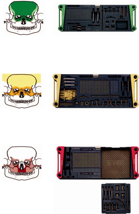
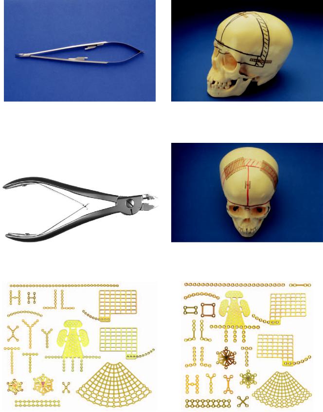
This system of instrumentation and titanium implants has been developed to address the individual needs of surgeons representing the many head and neck disciplines who perform craniomaxillofacial surgery. This set of implants is divided into different trays based on screw sizes. Each module contains the screws of a specific dimension with corresponding bone plates, mainly for cranial and midfacial locations, with certain mandibular applications. Although the instruments, implants, and screws have the same specifications, there are differences in the way that the modules are configured for North America and other parts of the world. North American instruments are distributed by Synthes Maxillofacial, Paoli, PA, while the rest of the world is supplied by STRATEC Medical, Oberdorf, Switzerland and Mathys LTD Bettlach, Bettlach, Switzerland. All products are AO/ASIF official devices accepted by the special TK (Technical Commission). The Craniofacial Modular Fixation System and COMPACT MF™) instrument modules are organized as separate color-coded trays containing screws of a particular size (1.0 mm, 1.3 mm, 1.5 mm, and 2.0 mm), with corresponding implants and varied stop drill bits (Figures 41.1–41.11). The Craniofacial Modular Fixation System (North American) consists of a graphic case (Figure 41.12), which contains the different tray modules up to a maximum of 4 in. (below) with the Universal Instrument Tray (above). The Craniofacial Modular System consists of 1.0-mm, 1.3-mm, 1.5-mm, 2.0-mm, 1.3-mm/1.5-mm/2.0-mm orthognathic and mesh modules. The COMPACT MF™ System consists of 1.0-mm, 1.3- mm, 1.5-mm, and 2.0-mm modules and has a sterilization tray with the modules stored side by side (Figure 41.13), but they can then be stacked atop the Universal Instrument Tray (Figure 41.14). The 1.3-mm/1.5-mm/2.0-mm orthognathic and mesh
modules are only available for the Craniofacial Modular System in North America. Mesh implants are available for the COMPACT MF™ system and can be stored in the auxilliary bin of the modules. The SYNTHES Maxillofacial Craniofacial Modular System and COMPACT MF™ plates, screws, and instruments are exactly the same. The only differences are the ways in which they are arranged in modules or as sets. The 1.3- mm, 1.5-mm, 2.0-mm system drill bits have preset stops at 4 mm, 6 mm, 8 mm, and 12 mm. The micro 1.0-mm system drill bits have preset stops at 3 mm, 5 mm, and 8 mm to prevent the unwanted penetration of associated vital structures. The drill bits are also available as Stryker J-latch, Universal/Hall, Jacob’s Chuck and Mini/quick coupling ends. The trays also contain the next size of screws for emergency purposes. A separate Universal Instrument Tray contains the Universal Instruments, which in the Craniofacial Modular System is in the top shelf of the graphic case. The drill bits are held within the lift-out lid that sits inside the auxilliary bin of the Universal Instrument Tray. The auxilliary bin may contain additional instruments. The Universal Instruments consists of the wide-handled screwdriver handle (1 each); narrow-handled screwdriver handle (1 each); plate bending pliers (2 each) (Figure 41.15); right-angle bender (Figure 41.16); plate holding forceps (Figure 41.17); plate cutter; and 1.0/1.3-mm plate holding Castro-Viejo locking forceps (1 each) and 1.5/2.0-mm plate holding Castro-Viejo locking forceps (1 each) (Figure 41.18); and the 3-in-1 plate bender/cutter (Figure 41.19), ratcheting screwdriver (Figure 22.27), and battery powered screwdriver (Figure 22.28).
1.0-mm Module
Color: Green
Indications: Cranium, nasal–orbital–ethmoid.
The 1.0-mm module is a microsystem containing 1.0-mm selftapping screws in 2-, 3-, 4-, 5-, 6-, 7-, and 8-mm lengths (additional lengths available up to 14 mm) and 1.2-mm emergency screws in 2-, 3-, 4-, 5-, 6-, 7-, and 8-mm lengths
445
446 |
A.M. Greenberg and J. Prein |
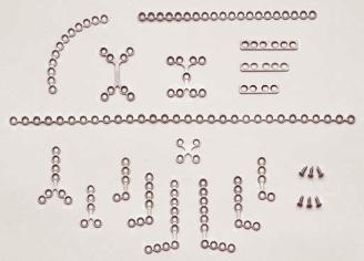
FIGURE 41.1 Craniofacial Modular Fixation System (1.0-mm Module). (Courtesy of Synthes Maxillofacial, Paoli, PA)
FIGURE 41.2 Craniofacial Modular Fixation System (1.3-mm Module). (Courtesy of Synthes Maxillofacial, Paoli, PA)
FIGURE 41.3 Craniofacial Modular Fixation System (1.5-mm Module). (Courtesy of Synthes Maxillofacial, Paoli, PA)

41. AO/ASIF Craniofacial Fixation System Hardware |
447 |
FIGURE 41.4 Craniofacial Modular Fixation System (2.0-mm Module). (Courtesy of Synthes Maxillofacial, Paoli, PA)
(additional lengths available up to 14 mm). Number-em- bossed markers attach to the top of each modular screw row to indicate the screw length for the customized module in use. The corresponding drill bits for plate fixation are 3 mm 0.70 mm with stops (2 each) for 2- to 3-mm length screws and 5 mm 0.76 mm (2 each) for 4-mm and 5-mm length screws and 8 mm 0.76 mm (2 each) for 6-, 7-, and 8-mm length screws. For lag screw technique, the 1.1-mm 110-
mm bit contained in the lift-out lid of the auxilliary bin is for the gliding hole; and the 0.76-mm bits are for the threaded hole. These 1.0-mm implants are a variety of X, Y, double Y, H (6 and 11 holes), T, L (left and right) and, curved (orbital rim), straight (adaptation), double row (strut), mesh plates, and burr hole covers (Figure 41.20).
The single and double Y plates are especially useful for nasal fractures and osteotomies. The double Y and H plates
FIGURE 41.5 Craniofacial Modular Fixation System (Mesh Module). (Courtesy of Synthes Maxillofacial, Paoli, PA)
448 |
A.M. Greenberg and J. Prein |
a
b
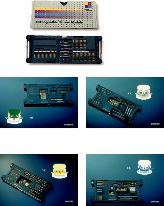
FIGURE 41.6 1.3-mm/1.5-mm/2.0-mm Orthognathic Modular Fixation System. (a) Orthognathic Plate Module. (b) Orthognathic Prebent Plate Module. (c) Orthognathic Screw Module. (Courtesy of Synthes Maxillofacial, Paoli, PA)
41. AO/ASIF Craniofacial Fixation System Hardware |
449 |
c |
FIGURE 41.6 Continued. |
FIGURE 41.7 COMPACT MF(TM) Craniofacial Set (1.0-mm Module). (Courtesy of STRATEC Medical, Oberdorf, Switzerland and Mathys LTD Bettlach, Bettlach, Switzerland)
FIGURE 41.9 COMPACT MF(TM) Craniofacial Set (1.5-mm Module). (Courtesy of STRATEC Medical, Oberdorf, Switzerland and Mathys LTD Bettlach, Bettlach, Switzerland)
FIGURE 41.8 COMPACT MF(TM) Craniofacial Set (1.3-mm Module). (Courtesy of STRATEC Medical, Oberdorf, Switzerland and Mathys LTD Bettlach, Bettlach, Switzerland)
FIGURE 41.10 COMPACT MF(TM) Craniofacial Set (2.0-mm Module). (Courtesy of STRATEC Medical, Oberdorf, Switzerland and Mathys LTD Bettlach, Bettlach, Switzerland)
450 |
A.M. Greenberg and J. Prein |
a
|
|
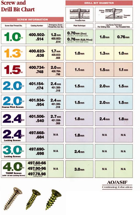
FIGURE 41.11 (a) Self-tapping screw and drill bit chart. |
b |
|
(b) Self-drilling screws: 1.3-mm, 1.5-mm, and 2.0-mm. |
|
(Courtesy of Synthes Maxillofacial, Paoli, PA) |
|
|
|
|
41. AO/ASIF Craniofacial Fixation System Hardware
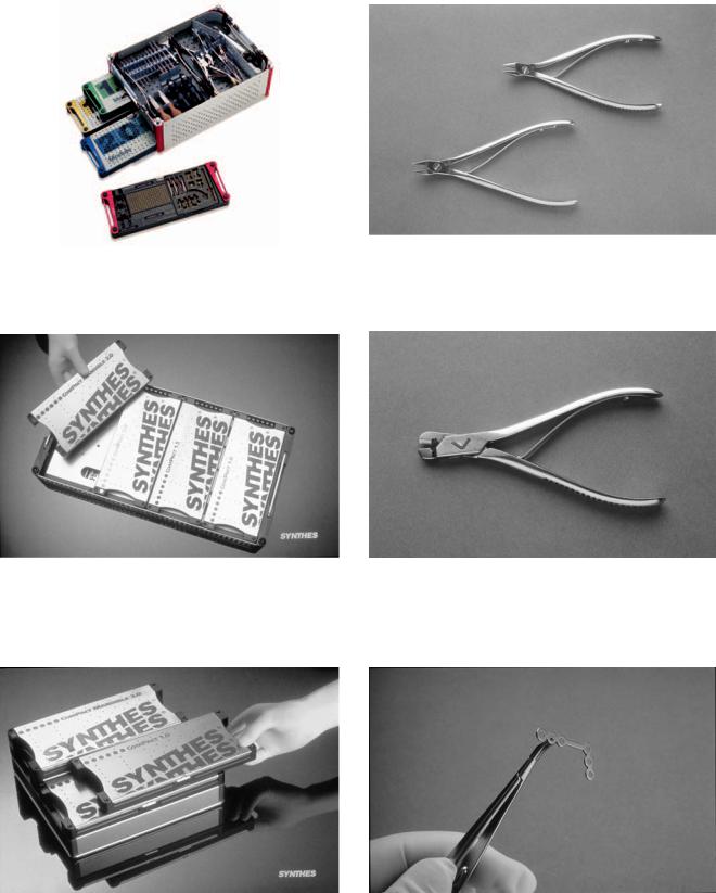
FIGURE 41.12 Craniofacial Modular Fixation System Graphic Case. (Courtesy of Synthes Maxillofacial, Paoli, PA)
FIGURE 41.13 COMPACT MF™ Sterilization Tray. (Courtesy of STRATEC Medical, Oberdorf, Switzerland and Mathys LTD Bettlach, Bettlach, Switzerland)
451
FIGURE 41.15 Plate bending pliers (2). (Courtesy of Synthes Maxillofacial, Paoli, PA)
FIGURE 41.16 Right-angle bender. (Courtesy of Synthes Maxillofacial, Paoli, PA)
FIGURE 41.14 COMPACT MF™ Modules stacked over the Universal Instrument Tray. (Courtesy of STRATEC Medical, Oberdorf, Switzerland and Mathys LTD Bettlach, Bettlach, Switzerland)
FIGURE 41.17 Plate holding forceps. (Courtesy of Synthes Maxillofacial, Paoli, PA)
452
FIGURE 41.18 Plate holding Castro-Viejo locking forceps. (Courtesy of Synthes Maxillofacial, Paoli, PA)
FIGURE 41.19 3-in-1 Plate bender/cutter. (Courtesy of Synthes Maxillofacial, Paoli, PA)
A.M. Greenberg and J. Prein
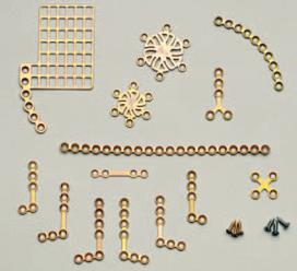
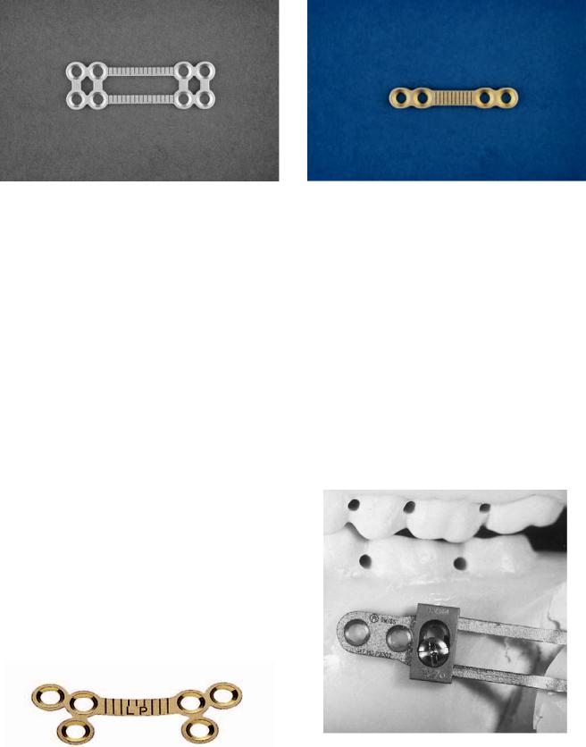
FIGURE 41.21 Strut plates demonstrated in a frontal bone advancement. (Courtesy of Synthes Maxillofacial, Paoli, PA)
FIGURE 41.22 Mesh plates demonstrated covering cranial defects. (Courtesy of Synthes Maxillofacial, Paoli, PA)
FIGURE 41.20 1.0-mm Module selection of implants. (Courtesy of Synthes Maxillofacial, Paoli, PA)
FIGURE 41.23 1.3-mm Module selection of implants. (Courtesy of Synthes Maxillofacial, Paoli, PA)
41. AO/ASIF Craniofacial Fixation System Hardware
are designed for fixation of replaced craniotomy segments. T plates are indicated for frontal sinus and naso-ethmoid fractures and pediatric frontal bone advancements. Strut plates (6 30 mm and 6 42 mm) are useful in pediatric frontal bone advancements, frontal sinus wall fractures, and at the orbital rim (Figure 41.21). The mesh plates (29 40 mm, 38 42 mm, 50 100 mm, and 100 100 mm) can be used as a cranioplast for the coverage of cranial bone defects, orbital floor reconstruction, and bridging pediatric maxillary defects (Figure 41.22). The cruciform screwdriver blade with holding sleeve is included (1 to 2 each). In addition the following are available: the 1.0-mm universal orbital floor plate, the 1.0-mm medial wall plates (left and right), the 1.0-mm burr hole covers (12 mm 6 holes and 17 mm 6 holes). Drill bits with stop for right-angle drills are also available in 3 mm 0.70 mm), 5 mm, and 8 mm (0.76 mm).
1.3-mm Module
Color: Gold
Indications: Orbito-zygomatic, cranium, nasal–orbital–eth- moid.
The 1.3-mm module is a miniplate system containing 1.3-mm self-tapping screws in 3-, 4-, 5-, 6-, and 8-mm lengths (available in lengths up to 18 mm), 1.3 mm self-drilling screws in 4-, 5-, and 6-mm lengths, and 1.7-mm emergency screws in 3-, 4-, 5-, 6-, and 8-mm lengths (available in lengths up to 18 mm). Number-embossed markers attach to the top of each modular screw row to indicate the screw length for customized module in use. The corresponding drill bits for plate fixation are 1.0 mm in 4-, 6-, and 8-mm lengths with stops. For lag-screw technique, the 1.5-mm bit found in the lift-out lid of the auxilliary bin is for the gliding hole; the 1.0-mm bits are for the threaded hole. The implants are a variety of Y, T, oblique L 6-hole left and right, oblique L 7-hole left and right, curved (orbital rim), straight 24-hole (adaption), universal orbital floor plate, medial orbital wall plates (left and right), strut plate (43 mm 18 holes), mesh screen (100
mm100 mm), mesh plates (38 mm 53 mm, and 100 mm 100 mm), box plates (10 mm 5 mm 4 holes and 10 mm 10 mm 4 holes), 1.3-mm anatomic orbital floor plate, and burr note covers (12 mm 6 holes and 17 mm 6 holes) (Figure 41.23). The single Y plates are especially useful for nasal fractures and osteotomies. The burr hole covers are for coverage of craniotome holes. T plates are indicated for frontal sinus and naso-ethmoid fractures and pediatric frontal bone advancements. L plates can be used in fractures of the orbits and cranium, as well as incomplete maxillary fractures. The mesh screen, mesh plates, and box plates are for various cranial applications. The trays also include the 1.3-mm cruciform screwdriver blade with holding sleeve (1 each) and the 1.3-mm cruciform screwdriver blade (selfretaining) (1 each).
453
1.5-mm Module
Colors: Black (Compact MF for Europe and Worldwide) Red (Synthes Maxillofacial for North America) Indications: Orbito-zygomatic, maxillary
The 1.5-mm module is a miniplate system containing 1.5-mm self-tapping screws in 4-, 6-, 8-, 10-, and 12-mm lengths (available up to 18 mm), 1.5-mm self-drilling screws in 4-, 5-, 6-, 7-, and 8-mm lengths, and 2.0-mm emergency screws in 4-, 6-, 8-, 10-, and 12-mm lengths (available up to 18 mm). However, in thick and deep cortical bone it is often necessary to pretap the holes. The 1.5-mm tap (short and long) is contained within the lift-out lid of the auxilliary bin. The proper use of self-stop drill bits is also emphasized to ensure that the screw holes will be sufficiently deep. Number-embossed markers attach to the top of each modular screw row to indicate the screw length for the customized module in use. The corresponding drill bits for plate fixation are 1.1-mm (4-, 6-, 8-, and 12-mm) lengths, with stops (2 each). For lag-screw technique, the 1.5-mm bit is for the gliding hole and is found within the lift-out lid of the auxilliary bin; the 1.1-mm bit is for the threaded hole. The implants are a variety of Y, X, oblique L (5-hold left and right), oblique L (7-hole left and right), curved (8-, 10-, and 12-hole), straight (20-hole) (adaption), universal orbital floor, medial orbital floor (left and right), and the 1.5-mm anatomic orbital floor plate. (Figure 41.24). The single Y plates are especially useful for nasal fractures and osteotomies. The burr hole covers are for coverage of craniotome holes. T plates are indicated for frontal sinus and naso-ethmoid fractures, as well as frontal bone advancements. L plates can be used in fractures of the orbits and cranium and incomplete maxillary fractures. Curved plates are for the orbital rim. Adaption plates, which can be applied to any site, may be especially helpful in bridging defects and
FIGURE 41.24 1.5-mm module selection of implants. (Courtesy of Synthes Maxillofacial, Paoli, PA)
454
frontal bar fractures. The trays also include the 1.5-mm cruciform screwdriver blade with holding sleeve (1 each) and 1.5-mm cruciform screwdriver blade (self-retaining) (1 each).
2.0-mm Module
Color: Blue.
Indications: Orbito-zygomatic, maxillary.
The 2.0-mm module is a miniplate system containing 2.0-mm self-tapping screws in 4-, 6-, 8-, 10-, 12-, 14-, 16-, and 18-mm lengths (available up to 24 mm), 2.0 mm self-drilling screws 4- , 5-, 6-, 7-, and 8-mm lengths, and 2.4-mm emergency screws in 6-, 8-, 10-, 12-, 14-, 16-, and 18-mm lengths (available up to 24 mm). These screws can also be pretapped when used in thick cortical bone; 2.0-mm taps (long and short) are in the lift-out lid of the auxilliary bin. Number-embossed markers attach to the top of each modular screw row and indicate the screw length for the customized module in use. The corresponding bits for plate fixation are 1.5-mm (4-, 6-, 8-, and 12-mm lengths, with stops). The proper use of the drill bits requires that they are used to drill to the proper depth. For lag-screw technique, the 2.0- mm 110-mm bit is for the gliding hole and is in the lift-out lid of the auxilliary bin. The 1.5-mm bit is for the threaded hole. The implants are a variety of Y (5 and 8 holes), X, H (8 and 9 holes), oblique L (5-hole left and right), Oblique L (7-hole left and right), Oblique L (10-hole left and right), Curved (8, 10, and 12 holes), adaption plate (20 holes), adaption plate with broad hole spacing (30 holes), and DCP (4, 5, and 6 holes) (Figure 41.25). The single Y and L plates are especially useful for LeFort I fractures and osteotomies, as they allow the placement of screws superior to the root apices of teeth. Adaption plates may be used for LeFort I fractures, bridging of defects, and reconstruction. DCP plates are for the frontozygomatic sites. X, H, and double Y are indicated for naso-orbito-ethmoid region
FIGURE 41.25 2.0-mm Module selection of implants. (Courtesy of Synthes Maxillofacial, Paoli, PA)
A.M. Greenberg and J. Prein
fractures. The trays also include the 2.0-mm cruciform screwdriver blade with holding sleeve (1 each) and 2.0-mm cruciform screwdriver blade (self-retaining) (1 each). In the Compact MF system the 2.0 mm Midface Plates are stored together with the 2.0 mandible plates in a combined 2.0 module.
1.3-mm/1.5-mm/2.0-mm Orthognathic
Modular Fixation System
Color: Black (Synthes Maxillofacial: North America availability only).
Indications: Orthognathic surgery of the maxilla and the mandible.
The Orthognathic Modular Fixation System is a composite 1.3-mm/1.5-mm/2.0-mm system available only in North America. It consists of a graphic case organized with an upper section lift-out standard screwdriver instrument tray or ratcheting screwdriver instrument tray and two separate lower section screw and implant modules. The Orthognathic Screw Module (Figure 41.6c) contains 1.3-mm self-tapping screws in 3-, 4-, 5-, and 6-mm lengths (available up to 18 mm), 1.7- mm self-tapping teal colored emergency in 3-, 4-, 5-, and 6- mm lengths (available up to 18 mm), 1.5-mm StarDrive selfdrilling screws (for star shaped screwdriver tip) in 4-, 5-, 6-, 7-, and 8-mm lengths, 2.0-mm StarDrive self-drilling screws with screws in 4-, 5-, 6-, 7-, and 8-mm lengths (available up to 18 mm), 2.0-mm self-tapping gold-colored screws (available up to 24 mm) and 2.4-mm emergency teal-colored screws (available up to 24 mm). Number-embossed markers attach to the top of each modular screw row to indicate the screw length for the customized module. The corresponding drill bits for plate fixation are the 1.0-mm drill bit Stryker J latch (4-, 6-, and 8-mm lengths with self-stops—2 each), 1.1-mm (4-, 6-, 8-, and 12-mm lengths with self-stops—2 each) and 1.5-mm (4-, 6-, 8-, and 12-mm lengths with self-stop—2 each). The proper use of the drill bits requires that they are used to drill the proper depth. For the 1.5-mm lag-screw technique, the 1.5-mm bit is for the gliding hole; the 1.1-mm bit is for the threaded hole. For 2.0-mm lag-screw technique, the 2.0-mm 110-mm bit is for the gliding hole. The Orthognathic Plate module (Figure 41.6a) contains a variety of maxillary and mandibular implants. The maxillary miniplates (Figure 41.26) consist of L plates 1.5-mm and 2.0-mm left and right (3 3 hole in 22-, 24-, 26-, 27-, and 29-mm lengths); oblique L plates 1.3-mm left and right (3 3, 3 4 holes), 1.5-mm left and right (2 3, 3 4, 2 2 holes short and long), 2.0-mm left and right (2 3, 3 4, 4 6, 2 2 short and long); oblique L plates malleable left and right 1.5-mm (2 3, 3 4, 2 2 holes long and short), 2.0- mm (2 3, 3 4, 2 2 holes long and short); adaption plates 1.3-mm (24 holes), 1.5-mm (20 holes) (regular and low profile); 2.0-mm, adaption plates malleable 1.5-mm and 2.0-mm (20 holes) T plates 1.3-mm (3 4 holes), 1.5-mm
41. AO/ASIF Craniofacial Fixation System Hardware |
455 |
FIGURE 41.26 1.5-mm/2.0-mm Orthognathic Module selection of implants. (Courtesy of Synthes Maxillofacial, Paoli, PA)
(4 7 holes), 1.5-mm malleable (4 7 holes); Y plates (1 3 holes) in 1.3-mm, 1.5-mm, 1.5-mm (low profile) and 2.0- mm (2 4 holes); Y plates malleable 1.5-mm (1 3 holes) and 2.0-mm (1 3 holes); Z plates left and right 1.5-mm short and long, 2.0-mm short and long; Z plates malleable left and right 1.5-mm short and long and 2.0-mm short and long, and pre-bent maxillary plates left and right for 3-, 5-, 7-, 9-, and 11-mm advancement and are available as a separate Pre-Bent Module (Figure 41.6b). The oblique, L, Z, and pre-bent plates are especially useful for LeFort I osteotomies, as they allow the placement of screws superior to the root apices of teeth. Mandibular implants consist of a variety of implants. 2.0 chin plates come in a variety of shapes and lengths, such as the offset straight (3-, 5-, and 8-mm lengths) (Figure 41.27), the offset single bend (3-5-, 6-8-, 9-11-mm lengths) (Figure 41.28), and the offset double bend (4-, 6-, 8-, and 10-mm lengths) (Figure 41.29). For mandibular ramus sagittal split osteotomies the 2.0-mm implants include strut (8 holes) (Figure 41.30), curved low profile 6 holes 4-mm bar; 6 holes 8-mm bar; and
FIGURE 41.28 Chin plates-offset single-bend selection. (Courtesy of Synthes Maxillofacial, Paoli, PA)
6 holes, 12-mm bar, curved 6 holes 4-mm bar; 6 holes 8-mm bar (Figure 41.26), and 6 holes 12-mm bar) (Figure 41.31), curved (10 holes) and straight (4 holes) (Figure 41.32). A special adjustable plate with an adjustable slider for mandibular sagittal split osteotomies is also available (Figures 41.33 to 41.35). Thinner, more malleable, teal-colored implant versions of this system are also available. For the Compact MF system orthognathic plates are ordered separately and can be stored in the auxilliary bin of the 1.5 mm or 2.0 mm modules.
Mesh Module
Color: Black
Indications: Cranium, orbits.
The Mesh Module is designed for use as a cranioplast for the coverage of bony defects of the cranium and for the orbital walls and floor. The implants are 1.0-mm mesh plates (40
FIGURE 41.27 Chin plates-offset straight selection. (Courtesy of Syn- |
FIGURE 41.29 Chin plates-offset double-bend selection. (Courtesy of |
thes Maxillofacial, Paoli, PA) |
Synthes Maxillofacial, Paoli, PA) |
456
FIGURE 41.30 Sagittal split strut plate. (Courtesy of Synthes Maxillofacial, Paoli, PA)
mm 29 mm, 42 mm 38 mm, and 100 mm 50 mm), mesh screen for 1.0-mm screws (100 mm 100 mm), mesh plate for 1.3-mm screws (100 mm 100 mm and 38 mm 53 mm), and mesh screen for 1.3-mm screws (100 mm 100 mm) (Figure 41.36), contourable mesh plates rigid and malleable 1.3-mm square (38 45 mm), small and large arcs, circular 30-mm, 70-mm, and 100-mm diameters, and 1.5-mm small and large arcs and circular 30-mm, 70-mm, and 100mm diameters (Figure 41.37). These various implants may be modified to any size and shape with a mesh cutter instrument.
Cranial Modular Fixation System
This is a special modular system organized for use in neurosurgically related procedures only in the cranium. It is composed of a graphic case that can contain two modules with an upper Universal Instrument Tray that lifts out (Figure 41.38). The universal instrument tray consists of universal plate benders (2 each), plate cutter (1 each), and Castro-Viejo locking plate/screw forceps (2 each). There are 1.0-mm, 1.3-mm, and 1.5-mm modules available.
A.M. Greenberg and J. Prein
FIGURE 41.32 Sagittal split straight plate. (Courtesy of Synthes Maxillofacial, Paoli, PA)
1.0-mm Cranial Modular
Fixation System Module
Color: Green
Indications: Cranial bone flap fixation.
The 1.0-mm module (Figures 41.1 and 41.20) is a microsystem containing 1.0-mm self-tapping screws in 3-, 4-, and 5-mm lengths (additional lengths available up to 8 mm) and 1.2-mm emergency screws in 3-, 4-, and 5-mm lengths (additional lengths available up to 8 mm). Number-embossed markers attach to the top of each modular screw row to indicate the screw length for the customized module in use. The corresponding
|
FIGURE 41.33 A 2.0-mm titanium sagittal split plate with adjustable |
FIGURE 41.31 Sagittal split curved plate. (Courtesy of Synthes Max- |
slider (Split Fix) close up of slidably adjustable slot hole. (Courtesy |
illofacial, Paoli, PA) |
of Synthes Maxillofacial, Paoli, PA) |

458
FIGURE 41.38 Cranial Modular Fixation System Graphic Case. (Courtesy of Synthes Maxillofacial, Paoli, PA)
taining 1.3-mm cranial StarDrive self-drilling screws in 4- and 5-mm lengths, 1.3-mm cranial self-tapping screws in 3-, 4-, and 5-mm lengths, 1.7-mm cranial emergency self-tapping screws in 3-, 4-, and 5-mm lengths. Number embossed markers attach to the top of each modular screw row to indicate the screw length for the customized module in use. The corresponding drill bits for plate fixation are 1.0 mm in 4-mm and 6-mm lengths with stops. For lag-screw technique, the 1.5-mm 110-mm bit found in the lift-out lid of the auxilliary bin is for the gliding hole; the 1.0-mm bits are for the threaded hole. The implants are a variety of straight (2 and 4 holes), Y (5 holes), X (4 holes), box plates (4 holes 5 mm and 10 mm), adaption plate (24 holes), strut plate (18 holes), burr hole covers (12-mm 6-mm holes and 17-mm 6-mm holes), and mesh plate (11-mm 8-mm holes). The trays also include the 1.3-mm cruciform screwdriver blade with hold-
FIGURE 41.39 A 1.3-mm Cranial Module. (Courtesy of Synthes Maxillofacial, Paoli, PA)
A.M. Greenberg and J. Prein
FIGURE 41.40 A 1.5-mm Cranial Module. (Courtesy of Synthes Maxillofacial, Paoli, PA)
ing sleeve (1 each), 1.3-mm cruciform screwdriver blade (selfretaining (1 each), and 2 black narrow screwdriver handles.
1.5-mm Cranial Modular
Fixation System Module
Color: Red.
Indications: Cranial bone flap and cranial fracture fixation.
The 1.5-mm module (Figure 41.40) is a miniplate fixation system containing 1.5-mm cranial StarDrive self-drilling screws in 4-, 5-, and 6-mm lengths, 1.5-mm self-tapping screws in 4-, 5-, and 6-mm lengths, and 2.0-mm emergency self-tapping screws in 4- and 5-mm lengths. Additional 1.5-mm brow lift screws self-tapping (14 mm), and StarDrive self-drilling (14 and 18 mm) are also available for brow lift surgery. They are removed after initial healing. The proper use of self-stop drill bits is also emphasized to ensure that the screw holes will be drilled to a sufficient depth. Number-embossed markers attach to the top of each modular screw row to indicate the screw length for the customized module in use. The corresponding drill bits for plate fixation are 1.1 mm (4-mm and 6-mm lengths with stops—2 each). For lag-screw technique, the 1.5-mm bit is for the gliding hole and is found within the lift-out lid of the auxilliary bin; the 1.1-mm bit are for the threaded hole. The implants are a variety of (5 holes), X (4 holes), adaption (20 holes), box plate (10-mm 4-mm holes), burr hole covers (12 mm and 17 mm). The burr hole covers (Figure 41.41) are for the coverage of craniotome holes. Adaption plates can be applied to any site and may be especially helpful in bridging defects and frontal bar fractures. The trays also include the 1.5-mm cruciform screwdriver blade with holding sleeve (1 each), 1.5-mm cruciform screwdriver blade (self-retaining) (1 each), and narrow black handles (2 each).
41. AO/ASIF Craniofacial Fixation System Hardware |
459 |
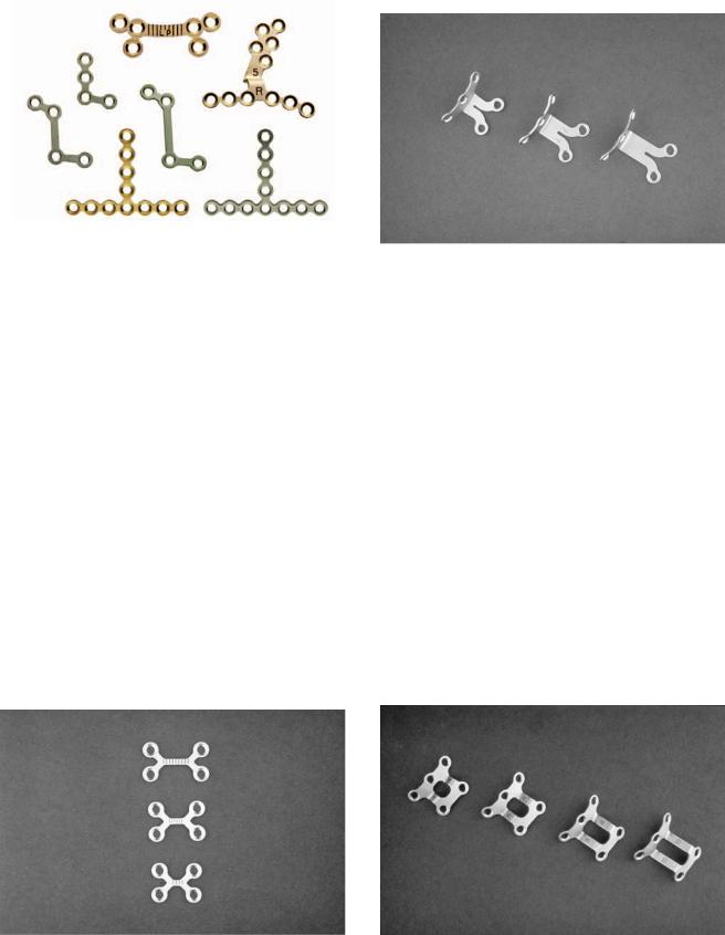
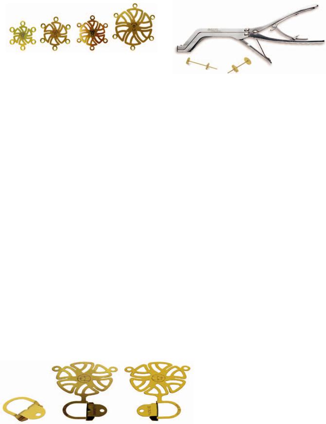
FIGURE 41.41 Cranial Modular System burr hole covers available in different diameters in 1.3-mm and 1.5-mm modules. (Courtesy of Synthes Maxillofacial, Paoli, PA)
FIGURE 41.43 Titanium cranial flap tube clamps with crimping device. (Courtesy of Synthes Maxillofacial, Paoli, PA)
Cranial Flap Spring Clips
and Tube Clamps
The cranial flap spring clips, spring clips with combination burr hole covers, and tube clamps are used for the fixation of cranial flaps (Figures 41.42 and 41.43). The tube clamps are available in 13-mm and 18-mm diameters. For the tube clamps, a crimping device is used to squeeze the clamp disks together to the desired tightness with the solid disk intracranial. The tube is then crimped and sheared by squeezing the second trigger.
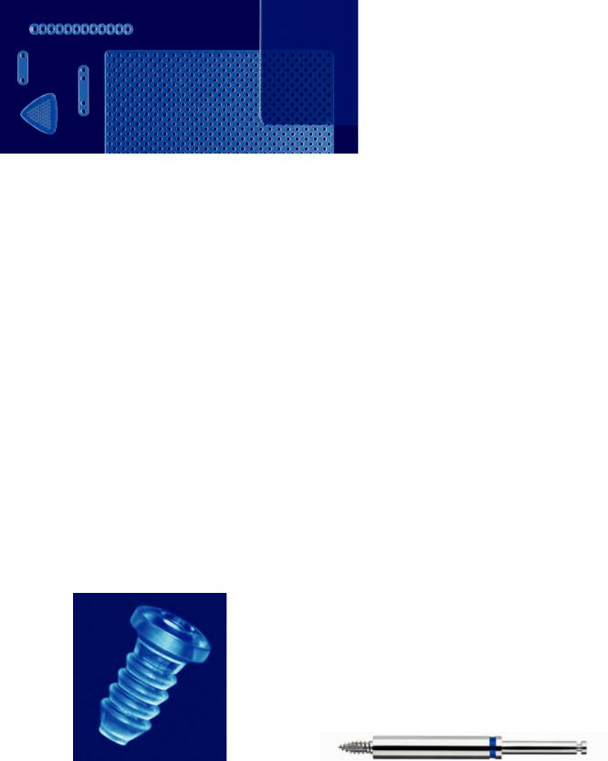
Resorbable Fixation System
Indications: Craniofacial, orthognathic, and trauma surgery.
The Resorbable Fixation system is a newly devised plate system (Figures 41.44 and 41.45) for use in craniofacial, orthognathic, and trauma surgery, but not intended for use in the mandible. The system is indicated for fragmented fractures of the naso-ethmoid and infraorbital regions, fragmented frontal sinus wall fractures, midfacial fractures, and reconstructive procedures of the midface or craniofacial skeleton. The plates and screws are manufactured from a resorbable copolymer, in a 70:30 poly(L/lactide-co-D, L-lactide) which resorbs in vivo by hydrolysis into lactic acid and then undergoes metabolism. Resorbable Fixation 1.5-mm and 2.0-mm
screw holes need to be pretapped with self-drilling 1.5-mm and 2.0-mm taps (Figure 41.46).
Use of the Resorbable Fixation system is contraindicated in the presence of active infection, limited vascular supply, insufficient bone quality or quality, and latent infections. The Resorbable Fixation system is not intended for use in mandibular fixation or under conditions of full load bearing. The resorbable implants are shaped through the use of a water bath heater (Figure 41.47) or hot air system (Figure 41.48) that heats the plates or mesh in the operating room environment. The hot air system is for use in North America only. The hot air device is used after it has warmed up to the necessary operating temperature. A plate or mesh implant is held with forceps or by hand within the “U”-shaped nozzle or in front of the narrow nozzle. After approximately 5 to 10 seconds of hot air heating, the plate or mesh can be contoured and molded by hand. The plate is held in the desired form until the material has cooled sufficiently to become rigid. In order to obtain the required shape, a bending template may be utilized. The Hot Air System consists of a hot air device, stand, small nozzle, large nozzle, narrow nozzle interconnect cable, and power supply (Figure 41.48). With the exception of the power supply, the Hot Air System can be steam sterilized. The water bath heater achieves 70°C in 500 cc of water after 15 minutes as indicated by a “ready indicator.” As
FIGURE 41.42 Cranial Modular Fixation System spring clips and spring clips with burr hole covers. (Courtesy of Synthes Maxillofacial, Paoli, PA)
460 |
A.M. Greenberg and J. Prein |
with the hot air system, implants heated in the water bath heater must be held with plate holding forceps. Plates may be heated and contoured up to 10 times and can be contoured after 10 seconds of heating. The system contains 2.5-mm emergency resorbable screws (4-, 6-, and 8-mm lengths), 2.0-mm resorbable screws (4.6-, and 8-mm lengths), and 1.5-mm resorbable screws (4-, and 6-mm lengths). The 1.5-mm implants include straight plates (2 and 4 holes), adaption plates (8, 12, and 20 holes), orbital rim plate, oblique L left and right, Y plate, double Y plate, strut plates (2 10 and 2 18 holes), orbital floor plate .5-mm thick, 1.5-mm mesh plates .5 mm thick (50 50 mm, 60 80 mm, 100 100 mm), 1.5-mm mesh plates .8 mm thick (50 50, 75 75, 100 100, and 125 125 mm), 1.5-mm, .5-mm thick sheets (50 50 mm and 75 75 mm), and 1.5-mm, .8-mm thick sheets (50 50 mm and 75 75 mm). The 2.0-mm implants include straight plates (2 and 4 holes), adaption plates (8, 12, and 20 holes), orbital rim plate, oblique L left and right, Y plate, strut plate (2 10 holes), orbital floor plate .5 mm thick, 1.5-mm mesh plates 1.2-mm thick (48 48 mm and 78 78 mm), sheets
.5-mm thick (50 50 mm and 75 75 mm), sheets .8-mm thick (50 50 mm and 75 75 mm), burr hole cover, and X plate (Figure 41.44).
Resorbable plates of 1.5 mm are comparable in strength to
FIGURE 41.44 Selection of 1.5-mm and 2.0-mm resorbable fixation system plates. (Courtesy of Synthes Maxillofacial, Paoli, PA)
1.0-mm titanium plates, and 2.0-mm resorbable plates are comparable in strength to 1.3-mm titanium plates or 1.5-mm malleable titanium plates. The instruments include mesh scissors, plate cutter, plate holding locking forcep, self-drilling 1.5-mm and 2.0-mm taps, 1.5-mm/2.0-mm double drill guide, 2.0-mm/2.5-mm double drill guide, and screwdriver.
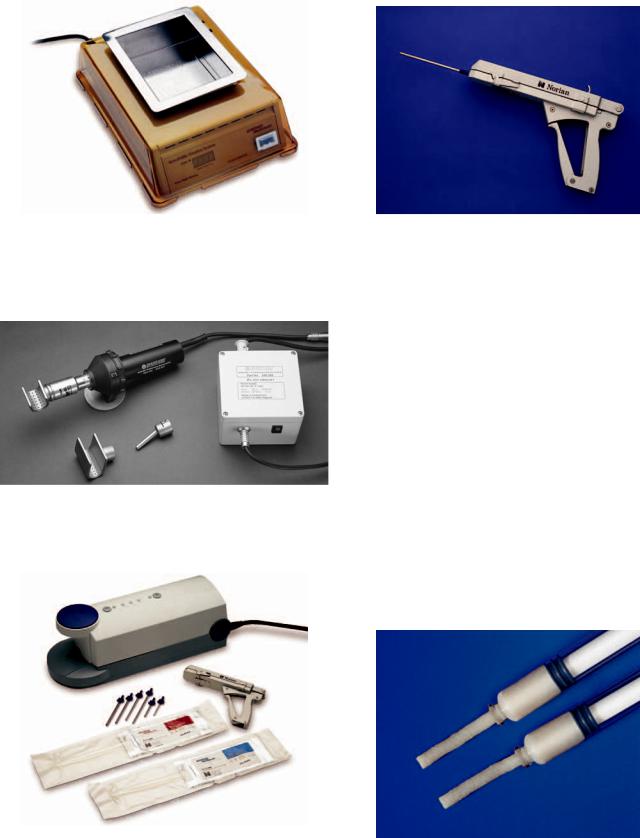
Craniofacial Repair System (CRS)
The Craniofacial Repair System (CRS) Figure 41.49 is a selfsetting calcium phosphate bone cement. It is used for the restoration or augmentation of defects of the craniofacial skeleton. CRS undergoes hardening to form dahlite, which closely replicates the mineral phase of bone, later gradually remodeling in two phases through osteoclastic resorption and the deposition of new bone by osteoblasts. CRS is an injectable and moldable bone cement that will harden in a warm, wet, or environment. Local tissue injury is not a consideration as it is nonexothermic, and it takes 10 minutes for the material to harden.
The CRS product delivery system reactant packs allow for consistent sterile cement mixing in premeasured amounts. The Reactant packs are available in 3-cc, 5-cc, and 10-cc sizes (Figure 41.49), with premeasured amounts of sodium phosphate and calcium phosphate powder. The reactant packs are mixed in the CRS automated mixer (Figure 41.49). The automatic mixer is powered by a single air hose between 90 to 150 psi operating room supply. If the automated mixer is not being used an alternated mortar, pestle, and spatula can be used.
After mixing the reactant packs are placed in the CRS delivery device (Figure 41.50), which allows ease of handling,
FIGURE 41.45 Example of resorbable screw. (Courtesy of Synthes |
FIGURE 41.46 Self-drilling taps (1.5-mm and 2.0-mm) for resorbable |
Maxillofacial, Paoli, PA) |
system screws. (Courtesy of Synthes Maxillofacial, Paoli, PA) |
41. AO/ASIF Craniofacial Fixation System Hardware
FIGURE 41.47 Water bath system. (Courtesy of Synthes Maxillofacial, Paoli, PA)
461
FIGURE 41.50 Craniofacial Repair System delivery device loaded for use. (Courtesy of Synthes Maxillofacial, Paoli, PA)
precise cement injection, and access to distant areas. There are different sized delivery needles to meet various surgical requirements. The amounts of CRS material needed to repair or fill various defects vary from 5 cc for a burr hole to 25 cc for a cranial defect or to obliterate the frontal sinus.
Demineralized Bone Matrix (DBX®)
Demineralized Bone Matrix (DBX®) is a 32% in putty and 27% in paste by weight human demineralized allogeneic bone
FIGURE 41.48 Hot air system with small, large, and narrow nozzles. graft for use in a variety of craniomaxillofacial osteoinduc- tive indications and is available as paste 1-cc, 5-cc, and 10-
cc syringes, and putty as 1-cc, 5-cc, and 10-cc syringes (Figure 41.51).
FIGURE 41.49 Craniofacial Repair System (CRS) mixer, 3-cc, 5-cc, and 10-cc reactant packs, delivery device, and delivery needles. (Courtesy of Synthes Maxillofacial, Paoli, PA)
FIGURE 41.51 Demineralized Bone Matrix (DBX®, putty and paste delivery syringes. (Courtesy of Synthes Maxillofacial, Paoli, PA)
42
Microvascular Reconstruction
of the Condyle and the Ascending Ramus
Rainer Schmelzeisen and Friedrich Wilhelm Neukam
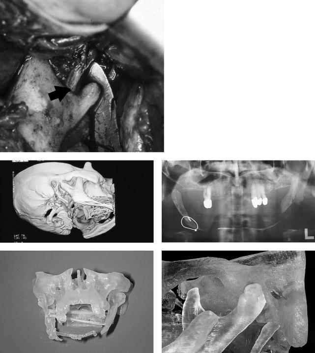
Today, temporomandibular joint (TMJ), condylar, and ascending ramus reconstruction can be performed with high accuracy as the recent new developments in diagnostic and surgical proceduresnowoffersafeandreliabletreatmentconcepts.Advances in diagnostic imaging facilitate treatment planning and the appropriate selection of reconstructive procedures (Figure 42.1).1
In general, nonvascularized grafts including costochondral, metatarsal, fibula, tibia, and iliac crest grafts are used.2–9 In an unfavorable soft tissue environment and especially in reconstructions of the condyle that also require reconstruction of larger aspects of the ascending ramus, an unpredictable resorption of the grafts may occur (Figure 42.2).
For condylar reconstruction, costochondral grafts are traditionally used. Disadvantages of these rib grafts are poor quality of cortical and medullary bone, flexibility, and elasticity of the bone. Warpage with continuous loading causing a possible separation between cartilage and bone as well as fractures may occur.10 In contrast to costochondral grafts, sternoclavicular grafts are morphologically and histologically very similar to the condyle throughout the growth process.11 Grafts used for TMJ reconstruction have a significant influence on mandibular growth, and they also influence maxillary growth processes.12 Nonvascularized grafts show graftspecific characteristics of growth capacity. Direct exposure of the medullary bone of the sternoclavicular graft to adjacent soft tissues may facilitate integration of the graft to systemic growth-stimulating or -inhibiting processes mediated via blood vessels. In general, growth inhibition or, often more problematic, growth overshoot of nonvascularized grafts cannot be predicted exactly (Figure 42.3).
Therefore, indications for the use of vascularized grafts for condylar and ascending ramus reconstruction may be given in situations of unfavorable soft tissue conditions, the intention to avoid resorption of the graft, and to facilitate easier integration of the graft to systemic growth processes mediated via blood vessels.
The use of vascularized grafts for TMJ reconstruction was first suggested by Siemssen in 1982.13 He suggested an arthroplasty of the TMJ with a sternoclavicular junction pedicled at
the sternocleidomastoid muscle. Reid also reported on a freeflap application of the clavicular head of the pectoralis major muscle as a vascularized clavicular bone graft.14
All reconstructive procedures for the ascending ramus including the condyle produce obvious technical challenges with inherent risks of mandibular deviation, malocclusion, ankylosis, and temporal bone erosion. Additional soft tissue deficits pose special problems.15 In microvascular reconstruction procedures of the mandible, there is an increasing interest in the special role of TMJ reconstruction.16–18
Material and Methods
Between 1988 and 1995, vascularized grafts from the iliac crest, the scapula region, and the fibula (n 53) were used for head and neck reconstructions, including reconstruction of the ascending ramus and condyle.
In all patients, preoperative conventional x-ray diagnostics were supplemented by computed tomographic (CT) scans, which in general were also available as three-dimensional reformations. Preoperative three-dimensional soft tissue and bone reconstructions gave valuable information for planning of the surgical procedures. The amount of mandibular repositioning following scar contraction and especially the necessity of repositioning a condylar process in secondary reconstructions prior to insertion of bone grafts could already be assessed preoperatively.
In patients with the condyle and parts of the ascending ramus left in place, the intraoperative repositioning of the condylar segment includes resection of the muscular process to avoid postoperative limitation of mouth opening.
After removal of all scar tissue adherent to the proximal condylar segment, the condyle may be temporarily fixed to the maxilla in its desired position with a long miniplate perforating the oral mucosa. In more complex mandibular reconstruction, additional prosthodontic devices facilitate orientation of the new mandible toward the maxilla if a later insertion of implants for prosthodontic treatment is planned (Figure 42.4).
462
|
42. Microvascular Reconstruction of the Condyle and the Ascending Ramus |
463 |
a |
FIGURE 42.1 In a 4-year-old boy with a Goldenhar syndrome, |
|
the intraoperative findings confirm the preoperative information about the hypoplastic condyle and the distance between condyle and temporomandibular fossa given by the preoperative three-dimensional image. (Arrow: inferior alveolar nerve). (b) Patient with severe arthrosis of the left condyle before costochondral reconstruction of the left condyle. A three-dimensional CT image reveals additional small-volume ankylosis between the right condyle and the zygomatic arch necessitating also open joint surgery on the right side. (c) Preoperative x-ray of an angle-to-angle defect. (d,e) With a three-dimensional model, fabricated according to CT data, a template facilitating intraoral contouring of the graft can be made.
b |
c |
d |
e |
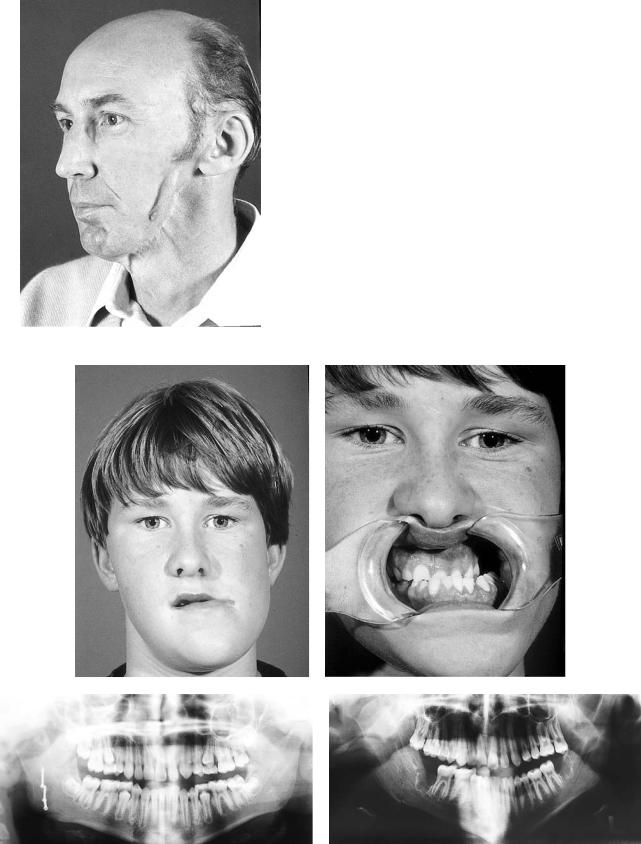
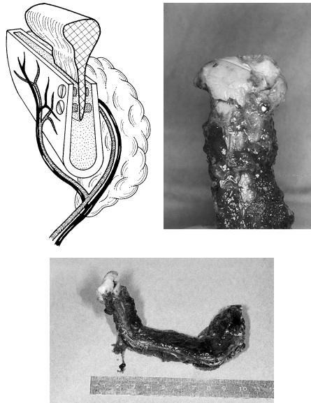
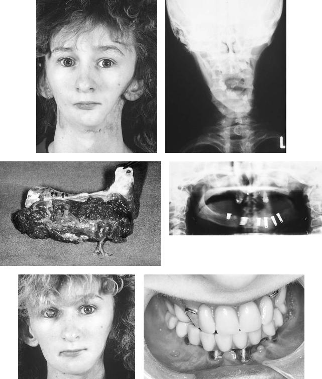
FIGURE 42.2 Severe resorption of a nonvascularized iliac crest graft for reconstruction of the ascending ramus and condyle in a 50-year-old patient. Note the pencil-like shape of the severely atrophic bone graft with additional soft tissue shrinkage.
|
|
|
|
|
|
|
|
|
|
|
|
|
|
|
|
|
|
|
|
|
|
|
|
|
|
|
|
|
|
|
|
|
|
|
|
|
|
|
a |
|
|
|
|
|
|
|
|
|
b |
||
|
|
|
|
|
|
|
|
|
|
|
|
|
|
|
|
|
|
|
|
|
|
|
|
|
|
|
|
|
|
|
|
|
|
|
|
|
|
|
|
|
|
|
|
|
|
|
|
|
|
|
|
|
|
|
|
|
|
|
|
|
|
|
|
|
|
|
|
|
|
|
|
|
|
|
|
|
|
c |
d |
FIGURE 42.3 (a,b) Twelve-year-old boy following reconstruction of the right condyle with a costochondral graft. Excessive growth overshoot 3 years after reconstruction with lateral deviation of the
mandible to the left. (c,d) X-ray of the patient immediately and 3 years postoperatively demonstrating the massive mandibular shift.

42. Microvascular Reconstruction of the Condyle and the Ascending Ramus |
465 |
a |
b |
c |
d |
FIGURE 42.4 (a) Three-dimensional soft tissue imaging before reconstruction of a defect of the right ascending ramus demonstrates lateral shift to the left side necessary for symmetrical chin projection. (b,c) Whereas the major mandibular segment has to be repositioned laterally to the left, the condyle has to be repositioned posteriorly and laterally. (d) In cases with the condyle still in situ, the condyle first is mobilized and the muscle process resected. After-
After positioning of the remaining condyle, plate fixation to the vascular graft should be performed at least with two or three screws at the condyle. Otherwise, removal of the condyle with replacement by the vascularized bone graft must be considered. Alternatively, the remaining condyle may be fixed to the proximal aspect of the vascularized graft according to Hidalgo.19,20 If a small condyle shows severe signs of osteoporosis with unsecure bone hold, the condyle should also be removed and replaced by the graft. In grafts with sufficient bone volume, an inlay-type osteotomy may facilitate fixation of the remaining short condyle with positioning screws (Figure 42.5).
Several donor sites are useful for reconstruction of the ascending ramus and condyle.
The iliac crest is suitable in cases necessitating reconstruction of larger aspects of the ascending ramus and condyle
ward, the condyle can be kept in its original position with the miniplate temporarily fixed to the maxilla. Then the length of the ascending ramus and the mandible can be estimated. Additional prosthetic devices fixed to the maxilla with screws in the midline may help to get an orientation for sagittal extension of bone grafts in patients with large mandibular reconstructions.
including potentially tooth-bearing areas of the posterior mandibular body. In these situations, the distal portions of the new mandible allow for insertion of dental implants (Figure 42.6). The grafts are mostly harvested from the ipsilateral hip, if ipsilateral donor site vessels are present. The pedicle then arises at the angle and an appropriate curvature of the graft is given. Defects of the ramus and condyle may be reconstructed with grafts from the contralateral hip, if the recipient vessels are on the contralateral side and the vascular pedicle is to be positioned at the chin area (Figures 42.7 and 42.8).
The ascending ramus may also be reconstructed with grafts from the scapula region which may offer a lower complication rate at the donor site and less graft volume compared to iliac crest grafts.15,20,21–24 The thin bone with a thicker lateral scapula border can easily be modeled to replace parts of
466 |
R. Schmelzeisen and F.W. Neukam |
a |
b |
c
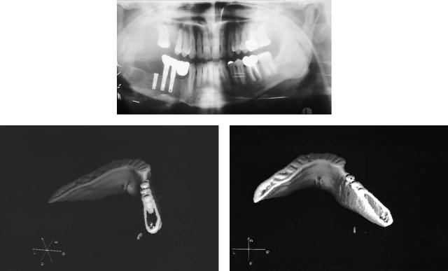
FIGURE 42.5 (a) If the condyle is still in situ, it may be fixed to a vascularized iliac crest graft with positioning screws after preparation of an inlay-like osteotomy. (b,c) The residual condyle is too small to be fixed in situ to a fibula graft. Therefore, the condyle was
the ascending ramus and the condyle. The volume of the necessary soft tissue component can be tailored individually ranging from different amounts of adherent muscle cuffs to a larger portion of deepithelialized soft tissue or even two separate skin flaps for extraoral and intraoral lining (Figures 42.9 and 42.10). The inferior aspect of the scapula tip forms the new condyle with a vascular pedicle located near the mandibular angle (Figure 42.11).
Today, fibula grafts are to be regarded as the grafts of
removed and fixed to the cranial aspect of a vascularized fibula graft. Care must be taken not to fracture thin aspects of the brittle bone during screw osteosynthesis.
choice for reconstruction even of smaller aspects of the ascending ramus and condyle. They can be harvested simultaneously and without changing the patient’s position on the operating table. Due to the segmental vascularization, various osteotomies are possible to match the shape of the original mandible. With experience, the osteotomies can be performed so that the fibula matches the mandibular angle and especially the slight outward deviation of the ascending ramus and the condyle in a cranial direction.
42. Microvascular Reconstruction of the Condyle and the Ascending Ramus |
467 |
a
b |
c |
FIGURE 42.6 (a) X-ray following reconstruction of the right body and ascending ramus with a vascularized iliac crest graft, dental implant insertion, and prosthodontic treatment with implant-fixed dentures. (b,c) Three-dimensional CT imaging of the posterior aspect of the
newly formed body of the mandible shows sufficient bone volume for insertion of dental implants. This sufficient bone volume with bicortical bone structure and a large volume of medullary bone is also given in the ascending ramus.
468 |
R. Schmelzeisen and F.W. Neukam |
a
b
FIGURE 42.7 (a) In situations with a bone defect at the side of the recipient vessels, the iliac crest graft is harvested from the ipsilateral hip.
(b) If the vessels are located at the contralateral side, the contralateral hip may be used to locate the vascular pedicle anteriorly.
a |
|
|
|
b |
|
|
|
|
|
|
|
|
|
|
|
|
|
|
|
c |
d |
e |
|
|
|
f |
|
|
|
|
|
|
|
|
|
|
|
|
|
|
|
|
|
|
|
|
FIGURE 42.8 (a,b) Sixteen-year-old female patient following hemimandibulectomy, full-dose chemotherapy, and radiotherapy for osteogenic sarcoma of the left mandible. (c) For reconstruction, a vascularized iliac crest graft was harvested from the ipsilateral hip. At that time, dental implants were inserted primarily. (d) Postoperative
x-ray. (e) Situation 1 year following reconstruction showing an adequate transverse relationship of the mandibular profile. (f) Intraoral situation after prosthodontic reconstruction with implant-borne dentures.
470 |
|
|
|
R. Schmelzeisen and F.W. Neukam |
a |
|
b |
||
|
|
|
|
|
|
|
|
|
|
c |
|
d |
|
|
|
e |
f |
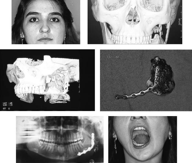
FIGURE 42.9 (a) Clinical view of a patient following resection of a bone tumor necessitating temporary reconstruction of the condyle and ascending ramus with a plate and condylar prosthesis. Slight soft tissue deficit in projection of the left preauricular region. (b,c) Threedimensional reconstruction of CT scan. (d) The preexisting plate was
used for fixation of a vascularized scapula bone graft. (e) Postoperative clinical aspect of the scapula graft for reconstruction of the condyle and the ascending ramus. (f) Postoperative aspect with undisturbed mouth-opening ability. (Patient operated on together with Dr. Hartmann, MD, DDS, at Dortmund City Hospital.)

42. Microvascular Reconstruction of the Condyle and the Ascending Ramus |
471 |
||||
a |
b |
||||
|
|
|
|
|
|
|
|
|
|
|
|
|
|
|
|
|
|
c |
|
|
|
d |
|
|
|
|
|
|
|
|
|
|
|
|
|
|
|
FIGURE 42.10 (a) Clinical situation of a female patient following hemimandibulectomy and postoperative irradiation. (b) Osteocutaneous parascapular flap for reconstruction of the posterior aspect of the mandible and volume augmentation. (c) Postoperative clinical
The fibula must be positioned in such a manner that the vascular pedicle again points toward the donor site vessels in the angular region. The vascular pedicle then runs along the inner orposteriorsideofthebone.Inlargersegmentsoftheascending ramus to be reconstructed, the proximal end of the fibula can be shaped round and placed in the condylar fossa. The desired angle of the mandibular graft is positioned at a region where the pedicle enters the bone.19 Pedicle length can be increased by removing the proximal part of the fibula subperiostally (Figure 42.12). A resorbable suture or wire positioned at the newly shaped condyle may be helpful for temporary fixation of the fibula in the temporal fossa by fixation of the suture or wire at
aspect of the patient. (d) Postoperative x-ray. Bone graft fixation was performed with stable reconstruction plate because of the large flap volume.
the zygomatic arch. This type of fixation does not prevent caudal dislocation of the neocondyle postoperatively.
When a fibula graft offers the best solution for bony reconstructions but an additional soft tissue pedicle is needed, the indication may be given to combine a fibula graft with a radial forearm flap, which also allows considerable independence in positioning of the bone and the soft tissues. A precondition for this procedure is an adequate number of recipient vessels. Although it may be considered to anastomose a fibula flap at the distal side of the radial forearm flap or vice versa, there may be an increased risk to lose two flaps with one vascular complication (Figure 42.13).
472
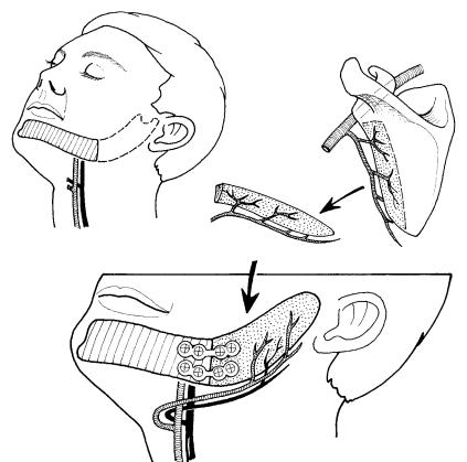
FIGURE 42.11 Schematic drawing of harvesting of scapula graft for reconstruction of the ascending ramus and condyle. The tip of the scapula is positioned in the temporal fossa. Thus the vascular pedi-
Discussion
Indications for isolated condylar reconstruction with vascularized grafts are rare if existent at all. If given indications, microvascular reconstruction of the ascending ramus and condyle is a challenge for the reconstructive surgeon, although the general failure in lateral or posterior mandibular defects is significantly lower compared to anterior mandibular defects.15
The graft selection has to be made with regard to the amount of bone necessary and the possible need for additional soft tissues. In our hands, the free fibula graft is to be regarded as the graft of choice for isolated bone defects. Additional soft tissue defects in composite reconstructions may be tailored with flaps from the scapula region. In selected cases and with regard to the patient’s general condition and the recipient vessels, a two-flap reconstruction with a fibula and a radial forearm flap may be indicated.
The aesthetic goal of posterior mandibular bone reconstruction is to provide a sufficient symmetrical sagittal chin projection and an adequate contouring of the mandibular angle. It has to be kept in mind that the distance between the condylar head and the angle is about 5 cm in general, and the
R. Schmelzeisen and F.W. Neukam
cle can point toward the angle or may also be positioned toward the midline if the recipient vessels are located on the contralateral side.
skin projection of the angle is slightly below the earlobe. Lengthening of the ascending ramus may result in an unnatural location of the angle. This effect may also occur by a gradual caudal displacement of the neocondyle of the bone graft, although in most cases no functional impairment occurs. This effect does not occur if the condyle is still present and grafts can be sufficiently fixed to it. However, efforts should be made for the correct anatomic positioning of the bone graft in the temporomandibular fossa and to provide a bilateral support of mandibular motion.
To overcome the tendencies for dislocation of the neocondyle and the ascending ramus, we more often keep patients in intermaxillary immobilization for 14 days in accordance with other authors.16,19,20,22 Afterward, postoperative functional therapy in cooperation with the Department of Physiotherapy is performed.
We do not feel it is necessary to fix additional temporomandibular joint prostheses on the cranial aspect of a vascularized graft.23
Also, mouth opening does not seem to depend greatly on positioning of the cranial aspect of a posterior bone graft, but rather on scar contraction of the soft tissues. Therefore, the
42. Microvascular Reconstruction of the Condyle and the Ascending Ramus |
473 |
a |
b |
c
d
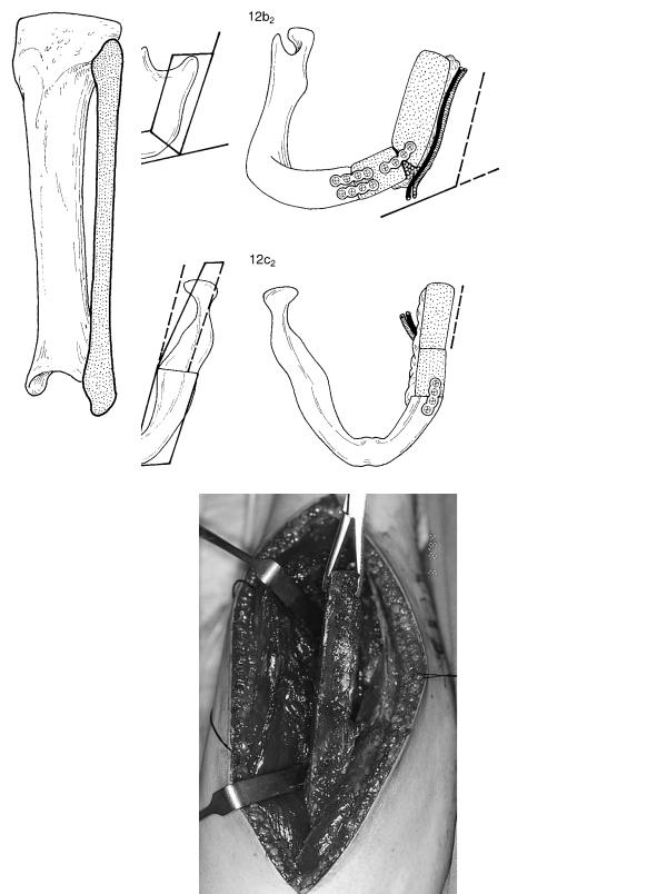
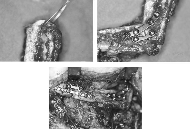
FIGURE 42.12 (a) The ipsilateral leg is chosen for reconstruction of a left-side defect. The vascular pedicle can be elongated by removal of proximal aspects of the fibula bone subperiostally. (b) To resemble the angle of the mandible, an osteotomy at the cranial and lin-
gual aspect of the fibula has to be made. The whole length of the ascending ramus averages about 5 cm. (c) Note the outward deviation of the ascending ramus. (d) Intraoperative aspect of a fibula after distal and proximal osteotomy.
474 |
R. Schmelzeisen and F.W. Neukam |
e |
f |
g
FIGURE 42.12 Continued. (e) A wire fixation of the neocondyle in the fibula may facilitate positioning of the graft. (f,g) Fixation of the fibula to the residual mandibular stump and fixation of the osteotomy sites is performed by miniplate osteosynthesis.
indication for resection of scars and, for example, additional intraoral soft tissue reconstructions has to be kept in mind.
Although miniplate fixation is to be regarded as the treatment of choice for fixation of vascularized bone grafts, in patients with free mandibular reconstructions and large graft volumes (i.e., composite grafts), rigid fixation of the graft may help to maintain the position of the bone in the fossa and avoid lateral displacement.24
Metatarsal grafts have been used for mandibular reconstruction.25 Experimental transplantation of vascularized second metatarsal joints show better results than reconstruction of the condyle with nonvascularized joint surfaces and demonstrate a reshaping of the new condyle during functional load.26 In addition to possible donor site complications, vascularized metatarsal grafts may not demonstrate better clinical results than nonvascularized grafts.27,28 Concerning the growth capability of vascularized grafts, additional factors, like the age of the patient at the date of operation, may in-
fluence the growth potential, as has been demonstrated for nonvascularized costochondral rib grafts.29
Although nonvascularized costochondral grafts have to be regarded as treatment modalities of choice for condylar reconstruction, in selected patients, vascularized bone and composite grafts allow for an individualized reconstruction with special attention to aesthetic and functional components. Perspectives for joint reconstruction also in the temporomandibular joint may be seen in further technical refinements of nonvascularized and vascularized bone grafts. Further investigation of timing of reconstruction and influence of other factors determining growth capacity of different bone grafts is necessary. Histopathological mechanisms of joints allografting in animal experiments are well understood. Clinical application is bound to additional information on duration and adverse effects of immunosuppression or to development of new immunosuppressive agents and may offer interesting perspectives for the future.30–32

42. Microvascular Reconstruction of the Condyle and the Ascending Ramus |
475 |
a |
|
b |
|
|
|
|
|
|
c |
d |
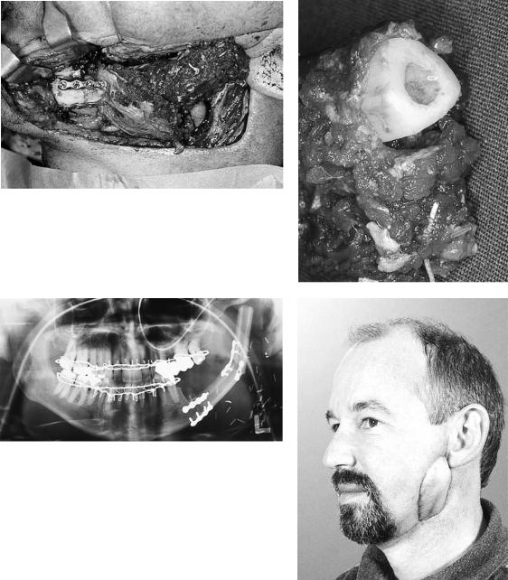
FIGURE 42.13 (a,b) Patient with osteoradionecrosis at the left angle of the mandible. (c,d) X-ray and intraoperative situation of the patient with two microplates for fixation of a temporary osteotomy in
situ. In addition to the need for vascularized bone grafts, there also is a lack of soft tissues due to the radiation and previous operations.
Continued.
476 |
R. Schmelzeisen and F.W. Neukam |
e |
f |
g |
|
h |
||
|
|
|
|
|
|
|
|
|
|
|
|
|
|
|
|
|
|
|
|
FIGURE 42.13 Continued. (e) The fibula graft is fixed anteriorly with two miniplates. (f) The proximal aspect of the mandible is removed subperiosteally. The neocondyle is rounded and placed in the temporal fossa. (g) An intermaxillary immobilization is performed for 2 weeks to keep the condyle in place. (h) Postoperative situation of the patient 6 weeks postoperatively shows adequate projection of the fibula in the soft tissue. The soft tissue was reconstructed by a radial forearm flap.
References
1.van der Kuijl B. Current role of conventional radiography and CT in TMJ treatment planning. Abstract, International TMJ Conference, September 1–3, Groningen, The Netherlands; 1994.
2.Rehrmann A. Osteoplastik am kindlichen Unterkiefer. Langenbecks Arch Klin Chir. 1961;299:184–188.
3.Dingmann RO, Grabb WL. Reconstruction of both mandibular condyles with metatarsal bone grafts. Plast Reconstr Surg. 1964;34:441–451.
4.Ware WH. Growth centre transplantation in temporomandibular joint surgery. In: Walker RV, ed. Transactions of the 3rd In-
ternational Conference on Oral Surgery. London; 1970:148– 157.
5.Kenett S. Temporomandibular joint ankylosis: the rationale for grafting in the young patient. J Oral Surg. 1973;31:744–748.
6.Matukas KJ, Szymela VF, Schmidt JF. Surgical treatment of bony anklyosis in a child using a composite cartilage-bone iliac crest graft. J Oral Surg. 1980;38:903–905.
7.Kummoona R. Chondro-osseous iliac crest graft for one stage reconstruction of the ankylosed TMJ in children. J Maxillofac Surg. 1986;14:215–220.
8.Lindqvist C, Pihakari A, Tasanen A, et al. Autogenous costochondral grafts in temporomandibular joint arthroplasty. A sur-
42. Microvascular Reconstruction of the Condyle and the Ascending Ramus |
477 |
vey of 66 arthroplasties in 60 patients. J Maxillofac Surg. 1986; 14:143–149.
9.Svensson B, Feldmann G, Rindler A. Early surgical-orthodon- tic treatment of mandibular hypoplasia in juvenile chronic arthritis. J Craniomaxillofac Surg. 1993;21:67–75.
10.Wolford LM, Cottrell DA, Henry C. Sternoclavicular grafts for temporomandibular joint reconstruction. J Oral Maxillofac Surg. 1994;52:119–128.
11.Ellis E III, Carlson DS. Histologic comparison of the costochondral sternoclavicular and temporomandibular joints during growth in Macaca mulatta. J Oral Maxillofac Surg. 1986;44:312.
12.Guyuron B, Lasa CI. Unpredictable growth pattern of costochondral graft. Plast Reconstr Surg. 1992;90(5):880–886.
13.Siemssen SO. Temporomandibular arthroplasty by transfer of the sterno-clavicular joint on a muscle pedicle. Br J Plast Surg. 1982;35:225.
14.Reid CD, Taylor GI, Waterhouse N. The clavicular head of pectoralis major musculocutaneous free flap. Br J Plast Surg. 1986; 39:57.
15.Boyd JB. Use of reconstruction plates in conjunction with softtissue free flaps for oromandibular reconstruction. Head Neck Reconstr. 1994;21(1):69–77.
16.Buchbinder D, Urken ML, Vickery C, Weinberg H, Biller HF. Bone contouring and fixation in functional, primary microvascular mandibular reconstruction. Head Neck. 1991;13(3):191–199.
17.Shenaq SM, Klebuc MJA. TMJ reconstruction during vascularized bone graft transfer to the mandible. Microsurgery. 1994; 15(5):299–304.
18.Shenaq SM, Klebuc MJA. The iliac crest microsurgical free flap in mandibular reconstruction. Clin Plast Surg. 1994;21(1):37– 44.
19.Hidalgo DA. Fibula free flap mandibular reconstruction. Head Neck Reconstr. 1994;21(1):25–35.
20.Hidalgo DA. Condyle transplantation in free flap mandible reconstruction. Plast Reconstr Surg. 1994;93(4):770–781.
21.Swartz WM, Banis JC, Newton ED, Ramasastry SS, Jones NF, Acland R. The osteocutaneous scapular flap for mandibular and maxillaryreconstruction.Plast Reconstr Surg.1986;77(4):530–545.
22.Urken ML, Weinberg H, Vickery C, Buchbinder D, Lawson W, Biller HF. Oromandibular reconstruction using microvascular composite free flaps. Arch Otolaryngol Head Neck Surg. 1991;117:733–744.
23.Lyberg T, Olstad OA. The vascularized fibular flap for mandibular reconstruction. J Craniomaxillofac Surg. 1991;19:113–118.
24.Schmelzeisen R, Rahn BA, Brennwald J. Fixation of vascularized bone grafts. J Craniomaxillofac Surg. 1993;21:113.
25.Watson DE. Condylar replacement with a metatarsal bone implant. Case report. Aust Dent J. 1990;35(4):362–363.
26.Hidding J, Habel G, Becker R. Kiefergelenkersatz durch ein mikrovaskulär reanastomosiertes mittelfußknochen-transplan- tat. Fortschr Kiefer Gesichtschir. 1990;35:25–27.
27.Dattilo DJ, Granick MS, Soteranos GS. Free vascularized whole joint transplant for reconstruction of the temporomandibular joint (a preliminary case report). J Oral Maxillofac Surg. 1986; 44:227.
28.Moos KH. The correction of the mandibular defect in hemifacial microsomia. J Craniomaxillofac Surg. 1994;22(suppl 1):8.
29.James D. The early management of hemifacial microsomia.
J Craniomaxillofac Surg. 1994;22(suppl 1):7–8.
30.Goldberg VM. Experimental models for joint allografting. In: Aebi M, Regazzoni P, eds. Bone Transplantation. Berlin: Springer-Verlag; 1989:68–75.
31.Goldberg VM, Herndon CH, Lance E. Biology of osteoarticular allografts. In: Aebi M, Regazzoni P, eds. Bone Transplantation. Berlin: Springer-Verlag; 1989:52–58.
32.Schmelzeisen R. Experimental reconstruction of mandibular defects with vascularized allogenic bone grafts. PhD thesis; 1991.