

19
Computerized Tomography and Its Use for Craniomaxillofacial Dental Implantology
Morton Jacobs
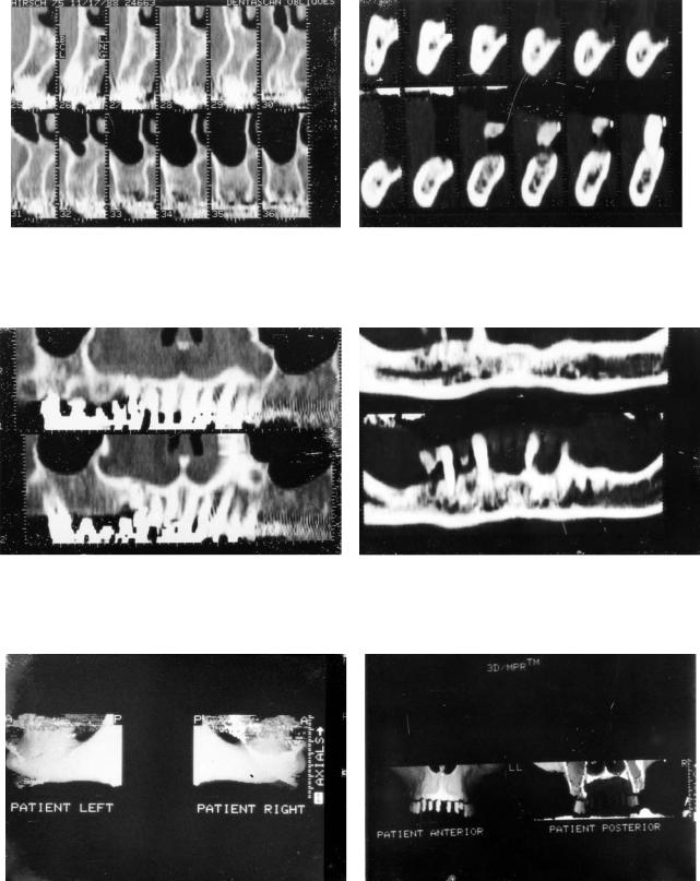
Recently, permanent dental implantation has gained wide acceptance because of the well-documented long-term surgical successes.1 In the past, preoperative x-ray evaluation has included lateral views of the skull, intraoral dental, and panoramic films. More recently, the use of coronal computed tomography (CT) has added another dimension to this eval- uation.2–3 The use of coronal CT has several important limitations. In older patients, it may not be possible because of cervical osteoarthritis. Even under the best of circumstances, it may not be entirely possible to obtain scans exactly perpendicular to the long axis of the mandible or maxilla. Perhaps the most serious drawback, however, are the beam-hard- ening artifacts generated by dental restorations already in the patient’s mouth (Figure 19.1).
The latest improvement in preoperative x-ray evaluation is the availability of sophisticated computer programs, such as the Dentascan (GE Medical Systems, Milwaukee, WI), which reformats standard axial CT images into a series of crosssectional oblique images that are oriented perpendicular to the curvature of the jaw.4–6 Additional panoramic CT images and 3D surface renderings are also available with the computer program. From a practical standpoint, the patient is positioned comfortably in a supine position with the head restrained to avoid motion artifacts between images, which would ultimately affect image quality. The lowest possible technical factors are used in combination with a bone algorithm, which enhances spatial resolution. Scanning is performed in the dynamic mode with contiguous or overlapping 1.0-mm-thick sections to again enhance spatial resolution. The images are oriented as nearly parallel to the mandible or maxilla as possible. If both the upper and lower jaw are to be scanned in one sitting, the head has to be repositioned to obtain the correct angulation (Figure 19.2). This serves two purposes: (1) It ensures the fewest number of slices, thereby reducing the x-ray exposure to the patient; and (2) it minimizes geometric distortion.
The computer program relies on the technique of reformatting. In a very simple way, the digital information inherent in the actual CT images are placed in the computer memory. The software program then rearranges this information to obtain the desired series of images.
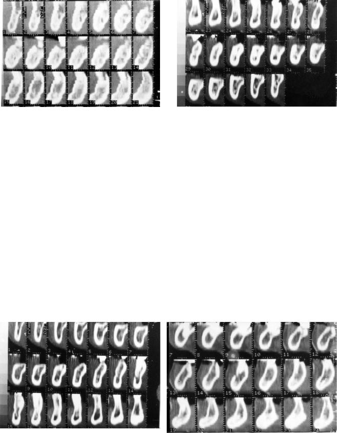
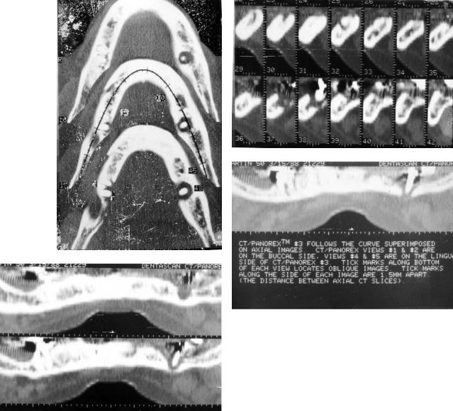
An axial CT image is selected from the series that corresponds to the roots of any remaining teeth. The physician or technologist then draws in a line corresponding to the curvature of the jaw (Figure 19.3). A series of lines is then prescribed perpendicular to this reference line (Figure 19.4). An oblique cross-sectional image is then obtained corresponding to each cut line, which represents a true cross section that corresponds to the curvature of the jaw (Figure 19.5). In addition, five panoramic tomographic sections are generated by the software program. The central image corresponds to the original prescribed cut line (Figure 19.6) with two on either side, buccally and lingually. Easy cross-referencing is possible among the axial, oblique, and panoramic images. The axial and panoramic images are used for orientation purposes to identify the edentulous areas in the jaw. Once these are localized, measurements of width and thickness of the bone are made from the oblique images. Frontal and lateral 3D surface renderings are shown in Figure 19.7.
These sophisticated computer programs can be used to determine the suitability and appropriate site of implant placement and the possible need for augmentation ridge surgery. Postoperatively, these imaging studies can show failure of an implant to osseointegrate to bone, improper placement of an implant, and violation of important structures.
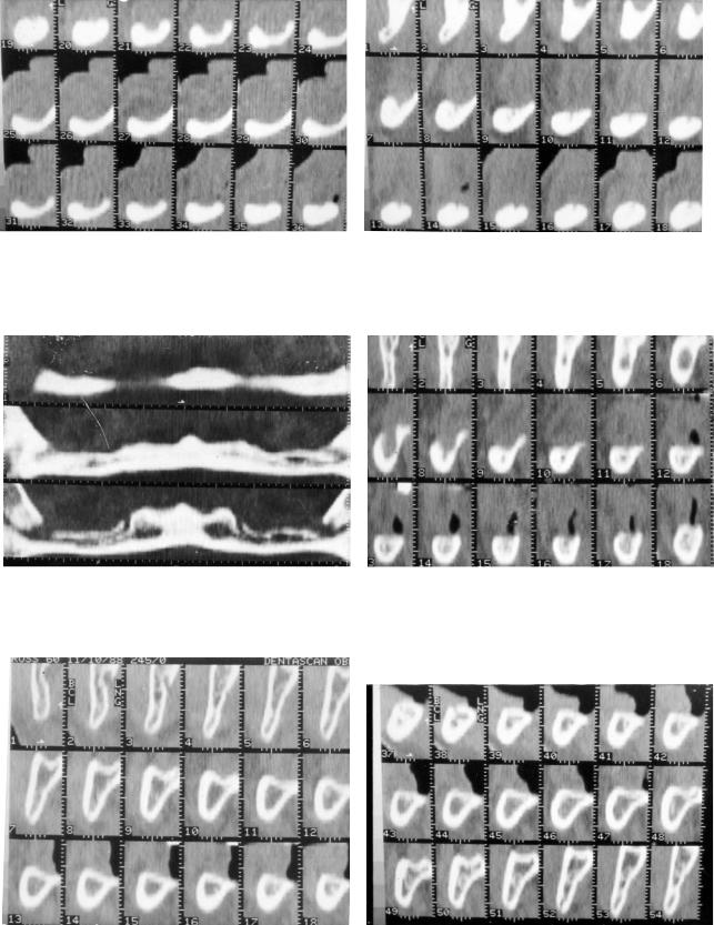
Let us now determine how the program can be helpful to the surgeon in preoperative evaluation. In the mandible, the surgeon needs to know thickness of alveolar bone, the contour of the alveolar ridge, and the position of the inferior alveolar nerve. In Figure 19.8, we can see the most common appearance of the inferior alveolar nerve, which images as a small dark hole surrounded by a faint cortical line. This is seen in approximately 50% of cases. The next most common appearance is a lucent area without a distinct cortical line and rounded, as seen in Figure 19.9. In this situation, visualization of the nerve depends on a normal amount of trabecular bone remaining in the body of the mandible. Figure 19.10 demonstrates the situation occurring when there is an osteopenic mandible with marked resorption of bony trabecula. Despite the excellent quality of images, the nerve cannot be easily recognized consistently on all the films. In this case, a
198

19. Computerized Tomography and Its Use for Craniomaxillofacial Dental Implantology |
199 |
FIGURE 19.1 Direct coronal CT demonstrates severe degradation of image quality secondary to dental restoration in the patient's mouth.
a
b
FIGURE 19.3 Prescription of reference line used for generation of oblique cross-sectional images.
FIGURE 19.2 Sagittal digital radiograph demonstrates patient positioning required for (a) mandibular and (b) maxillary studies. For the mandibular examination, the inferior border of the mandible is perpendicular to the table top, whereas for the maxillary study the hard palate is perpendicular to the table top.
FIGURE 19.4 Oblique cross-sectional images oriented perpendicular to the jaw along the reference line.
200 |
M. Jacobs |
a |
b |
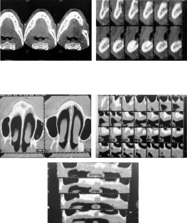
FIGURE 19.5 Series of computer-generated cross-sectional images in (a) maxillary and (b) mandibular examinations.
a |
b |
FIGURE 19.6 Computer-generated panoramic images along reference line in (a) maxillary and (b) mandibular examinations.
a |
b |
FIGURE 19.7 3D computer-generated surface renderings in (a) mandibular and (b) maxillary studies.
19. Computerized Tomography and Its Use for Craniomaxillofacial Dental Implantology |
201 |
FIGURE 19.8 Oblique cross-sectional images demonstrating inferior alveolar nerve. Typical appearance of nerve surrounded by thick cortical line.
FIGURE 19.9 Oblique cross-sectional images of inferior alveolar nerve appearing as a rounded lucency in body of mandible without distinct cortical line.
precise determination of the position of the nerve is not pos- |
bone covering the inferior alveolar nerve. There is, however, |
sible radiographically. Fortunately, this occurs in only 10% |
a small area of exposure of the nerve posteriorly in the body |
to 15% of cases. The position of the nerve relative to the buc- |
of the mandible. The central position of the nerve within the |
colingual cortices is readily determined as is the amount of |
body of the mandible precluded successful positioning of im- |
remaining bone between the nerve and the crest of the ridge. |
plants either buccally or lingually in the mandible. There is, |
The contour of the ridge is also well demonstrated. Any sig- |
however, adequate bone anteriorly for fixture placement. |
nificant downward sloping is easily recognized. |
The next two cases highlight the value of the technique in |
Several clinical cases are now presented that highlight the |
marginal situations. Panoramic view in the first case sug- |
usefulness of the Dentascan program. Figure 19.11 demon- |
gested lack of sufficient bone for implantation. The oblique |
strates a severely resorbed mandible in an elderly patient. Un- |
images (Figure 19.13) show a severely resorbed alveolar ridge |
der normal circumstances, the mental foramen exists approx- |
with little bone remaining between the nerve and the crest of |
imately one third of the way from the crest of the alveolar |
the ridge. The position of the nerve, however, which can be |
ridge. In this case, the mental foramen and nerve lie at the |
seen hugging the lingual cortex, allowed successful fixture |
ridge with no cortical bone covering the nerve. Resorptive |
placement buccally in the body of the mandible. In the next |
changes are present both anteriorly and posteriorly in the |
case, preliminary radiographic examination suggested ade- |
mandible, precluding successful intraosseous implantation. |
quate bone for implantation as suggested by the panoramic |
Figure 19.12 demonstrates another patient with a severely |
image (Figure 19.14a). The oblique view (Figure 19.14b), |
resorbed mandible posteriorly with only a small amount of |
however, demonstrates significant buccolingual atrophy with |
a |
b |
FIGURE 19.10 Osteopenic mandible with resorption of bony trabecula. The inferior alveolar nerve cannot be discerned.
202 |
M. Jacobs |
a |
b |
FIGURE 19.11(a+b) Examples of marked bony resorption of the alveolar ridge in the mandible. Inferior alveolar nerve is visualized at the crest of the ridge with little or no bony covering.
a |
b |
Figure 19.12 Severely resorbed mandible with localized area of exposure of the nerve seen on both (a) panoramic and (b) axial images.
a
b
FIGURE 19.13 (a,b) This demonstrates a marginal case with marked resorption of alveolar ridge initially precluding fixture placement. Position of nerve adjacent to the lingual cortex allowed fixture placement buccal to the nerve.
19. Computerized Tomography and Its Use for Craniomaxillofacial Dental Implantology |
203 |
b
a
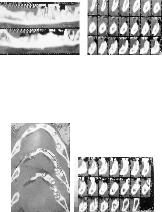
FIGURE 19.14 Appearance of adequate bone on plain film taken before the examination and panoramic images (a) suggest adequate bone. Oblique cross-sectional images (b), however, demonstrate buccolingual atrophy requiring alveolectomy or bone graft augmentation. Considerably less bone is available for final fixture placement.
sharp, tapered pointing of the ridge. The patient required alveolectomy and considerably less bone was therefore available for fixture placement. In both cases Dentascan imaging aided presurgical planning and influenced final decision-making.
Postoperatively, these imaging techniques are useful in assessing adequacy of osseointegration. Normally successful osseointegration demonstrates a tight metal-to-bone contact. Failure of osseointegration is evident by absent metal-to-bone contact with a lucent zone around the fixture representing fi-
brous tissue. Axial and oblique cross-sectional images in this case demonstrate fibrous osseointegration of the left incisor and premolar fixtures (Figure 19.15).
Violation of the mandibular canal by either improper drilling, fixture placement, or secondary infection can result in permanent injury to the inferior alveolar nerve. Usually, however, once it is recognized and adequate measures undertaken, this can be avoided.
In the following case (Figure 19.16), an implant placed in
a
b
FIGURE 19.15(a) Axial view and (b) oblique cross sectional images demonstrating fibrous osseointegration involving left incisor and premolar fixtures demonstrating faint lucent zone on original axial and oblique cross-sectional images.
204
a
c
M. Jacobs
b
d
FIGURE 19.16 Postoperative infection demonstrated on (a) axial, (b) oblique cross sectional, and (c,d) panoramic images as localized area of bony resorption around the fixture. Exposure of the inferior alveolar nerve and adjacent lingual cortex.
the immediate extraction site in the left molar region developed a localized infection within the tooth socket. There is extensive erosion of bone with exposure of the inferior alveolar nerve and the adjacent lingual cortex.
Improper implant placement is illustrated in the next case (Figure 19.17). The patient experienced paresthesia of the right lower left lip and chin after improper implant placement in the molar region. The implant is seen on the same axial image as the inferior alveolar nerve. Oblique cross-sectional images confirm violation of the canal by the fixture. Once removed, the paresthesia quickly resolved. In the maxilla, the surgeon again needs to know the height of alveolar bone, the contour of the ridge, and sinus pathology.
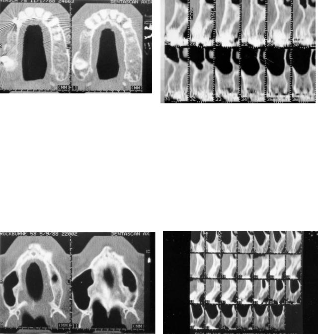
In our first case, a commonly encountered problem is rec- ognized—the large incisive canal. The axial image (Figure 19.18a) shows generalized resorption of the alveolar ridges.
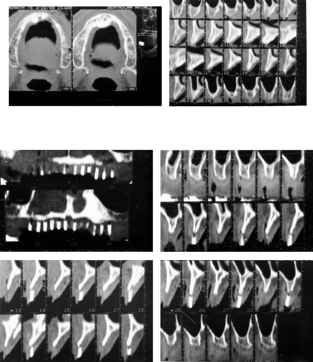
A large incisive canal is demonstrated which often accompanies the generalized resorptive change. This often limits fixture placement in the anterior premaxillary region. This change is again confirmed on oblique and panoramic images (Figures 19.18a,b). The next case highlights an interesting problem and an instructive case. In Figure 19.19a we see edentulous areas in the posterior alveolar regions. Adequate bone is present for fixture placement and no significant buccolingual atrophy is seen on oblique images (Figure 19.19b). Interestingly, the surgeon encountered great difficulty at operation owing to the softness of the bone. Perhaps the only limiting factor at the present time with many of these computer programs is the assessment of textural abnormalities of bone.
The problem of buccolingual atrophy, particularly in the premaxilla, is illustrated in Figure 19.20. Despite adequate height
19. Computerized Tomography and Its Use for Craniomaxillofacial Dental Implantology |
205 |
a |
b |
FIGURE 19.17 Improper fixture placement demonstrated on (a) axial and (b) oblique cross-sectional images. Involvement of the inferior alveolar nerve by the fixture is seen to excellent advantage.
a |
b |
|
c
FIGURE 19.18 Severe resorptive changes within the maxillary ridge. Associated enlargement of the incisive canal is seen on (a) original axial, (b) oblique cross-sectional, and (c) panoramic images.
206 |
M. Jacobs |
a |
b |
|
FIGURE 19.19 Edentulous area in posterior maxilla on the left with adequate bone for fixture placement (a). Softness of bone encountered at surgery was not recognized on preoperative imaging (b).
of the ridge, the severe buccolingual atrophy recognized on both axial and oblique views precludes fixture placement at the desired positions without further bone graft augmentation. In the next case, we see a situation of asymmetrical buccolingual atrophy. Adequate bone is seen on the right, but the severe buccolingual atrophy and tapering of the premaxilla on the left dictates an alveolectomy prior to fixture placement (Figure 19.21).
An interesting technique is illustrated in the following case.
The patient is scanned with a plastic stent with gutta percha markers placed at the sites where the surgeon wants to place fixtures. The radiologist can comment about the adequacy of bone at each site, permitting a direct correlation with the surgeon (Figure 19.22)
The final series of cases demonstrates the use of the Dentascan program in assessing maxillary sinus pathology with regard to posterior fixture placement. Figure 19.23 illustrates a
a |
b |
FIGURE 19.20 Severe buccolingual atrophy demonstrated on (a) axial and (b) oblique cross-sectional images.
19. Computerized Tomography and Its Use for Craniomaxillofacial Dental Implantology |
207 |
a |
b |
FIGURE 19.21(a) Axial and (b) oblique cross sectional images of asymmetrical buccolingual atrophy on the left required alveolectomy prior to fixture placement.
a |
b |
c |
d |
FIGURE 19.22 Patient scanned with radiopaque markers where surgeon desires to place fixtures. Direct correlation is available between (a) panoramic and (b–d) oblique cross-sectional images.
208
FIGURE 19.23 Normal panoramic image demonstrating clear maxillary sinuses with no inflammatory disease.
normal case without evidence of sinus pathology. The normally aerated sinuses are seen without abnormal tissue adjacent to the bone. Figure 19.24 shows inflammatory disease within the inferior recess of the right maxillary sinus imaging as polypoid soft tissue interposed between the alveolar ridge and aerated sinuses. Violation of the maxillary sinus by an implant is seen as possibly accounting for the infection. Although very accurate in defining soft tissue disease, the exact nature is uncertain. It may represent either submucosal edema, retained se-
FIGURE 19.24 Polypoid mucosal thickening within the alveolar recess right maxillary sinus.
M. Jacobs
a
b
FIGURE 19.25 Failed implants filled with granulation tissue is seen extending into the alveolar recess of the left maxillary incisor on both (a) panoramic and (b) oblique cross-sectional images.
cretions, or inflammatory tissue. Figure 19.25 again demonstrates inflammatory disease in the left maxillary sinus on both oblique and panoramic images. Three normal implants are seen within the anterior maxilla. Two failed implant sites are seen filled with granulation tissue. Infection extends into the alveolar recess of the left maxillary antrum.
The use of multiplanar reconstruction programs combined with CT scanning has greatly enhanced the success of intraosseous dental implantation. Although not necessary in every case, its use in difficult or marginal cases can often aid the surgeon in preoperative evaluation and surgical planning. Imaging of the maxillary sinus and posterior mandibular nerve-bearing regions, however, is often essential.
19. Computerized Tomography and Its Use for Craniomaxillofacial Dental Implantology |
209 |
References
1.Albrektsson T, Lekholm U. Osseointegration: current state of the art. Dent Clin North Am. 1989;33:537–544.
2.DelBalso AM, Hall RE. Advances in maxillofacial imaging.
Curr Probl Diagn Radiol. 1993;22:96–103.
3.Rothman SLG, Chafetz N, Rhodes ML, Schwartz MS. CT in the preoperative assessment of the mandible and maxilla for endosseous implant surgery. Radiology. 1988;168: 171–175.
4.Schwartz MS, Rothman SLG, Rhodes ML, Chafetz N. Computed tomography. I. Preoperative assessment of the mandible for endosseous implant surgery. Int J Oral Maxillofac Implants.
1987;2:137–141.
5.Schwartz MS, Rothman SLG, Rhodes ML, Chafetz N. Computed tomography. II. Preoperative assessment of the maxilla for endosseous implant surgery. Int J Oral Maxillofac Implants.
1987;2:143–148.
6.Abrahams JJ. Anatomy of the jaw revisited with dental CT software program. AJNR. 1993;14:979–990.
20A
Radiographic Evaluation
of the Craniomaxillofacial Region
Dorrit Hallikainen, Christian Lindqvist, and Anna-Lisa Söderholm
Panoramic and Plain Film Radiography
and Conventional Tomography
Preoperative radiographic evaluation of patients undergoing corrective or reconstructive bone surgery aims to evaluate the nature and extent of the lesion or deformity and to provide the surgeon with anatomic mapping of structures that are important in treatment planning. Follow-up examinations are performed to confirm healing and to discover complications at an early stage.
The selection of the most appropriate imaging method in each case has to take into account the diagnostic capability and cost-effectiveness of the investigation. Plain films are still used frequently, as for example in graft evaluation.1,2 Plain films, panoramic radiography, and conventional tomography can be performed at low cost and a low radiation dose, as compared to computed tomography (CT) examination, which exposes the imaged area to a substantially higher radiation dose.3
Good image quality is essential, and special attention must be paid to quality assurance. The entire chain of image acquisition, from selection of equipment to patient positioning, exposure, and dark-room processing has to be carefully controlled.
Imaging Methods
Panoramic Radiography
The panoramic view is the basis of imaging the dentition and mandible.4 It corresponds to plain film in other parts of the skeleton because the entire mandible is within the image layer of a single exposure. The form of the image layer and the direction of the beam (i.e., the projection) varies from one machine to the next, and several image layer profiles may be programmed into a single panoramic unit. In purely dental imaging, an orthoradial projection is usually the goal because it minimizes crown overlapping. An orthoradial projection, however, causes more ghost shadows of the opposite ramus than an oblique projection and may give origin to very dis-
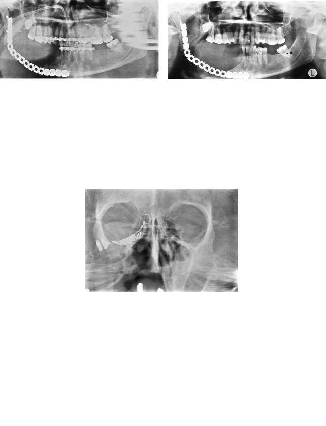
torted shadows in patients with metal fixation devices in the ramus or angular area. When the opportunity exists to select the projection in panoramic radiography, the lowest orthoradial beam direction is recommended for patients with bone plates (Figure 20A.1).
The use of panoramic radiography is well established in imaging the dentition and the entire mandible, but its use in other parts of the facial skeleton and in coned-down views has, until now, been limited. The panoramic technique of using rotating narrow-beam radiography is useful in imaging various parts of the facial skeleton, when image layer forms different from the conventional techniques are applied.5,6 Panoramic radiography of the middle face is usually carried out using a cylindrical image layer. It gives a good overall view of the midface. It can be complementary to plain films, or it can replace Waters’ and Caldwell projections (Figure 20A.2).5,7
Detailed narrow-beam radiography is a term used for coned-down views of various parts of the jaws.6 With this method, an area of 3 3 cm is imaged using the panoramic technique and a magnification of 1.7. The diagnostic capability of this technique has proven to be in dental radiology of the same quality as in periapical radiography.8,9 These findings may be partly owing to the understanding that detailed narrow-beam radiography includes four projections of the same area, and the images are stereoscopic pairs (Figure 20A.3). Detailed narrow-beam radiography is in our experience suitable for bone structure evaluation of the mandible and the alveolar process of the maxilla.10
Plain Films
Basic plain film series for the upper jaw include Waters’, Caldwell, and lateral projections, often supplemented with a submentovertex view.11 For the mandible, Towne’s and submentovertex projections are usually considered the standard series.
The plain films provide an overview of the lesion or deformity, and at follow-up examinations, they are used to evaluate the location of fixation plates and screws. Usually plain films do not permit early detection of subtle bone changes, such as those seen with infection or bone-graft failure.
210
20A. Radiographic Evaluation |
211 |
a |
b |
FIGURE 20A.1 (a) A panoramic image taken with orthoradial projection. Ghost shadows originating from the plate are present on the contralateral side. (b) A panoramic image of the same patient with
Multidirectional Tomography
Multidirectional, cross-sectional tomography is valuable both in preoperative mapping of the jaws and for the postopera-
a
b
a more oblique projection. There are no ghost shadows from the metal plate. There is no overlapping of teeth crowns and a part of the atlas overlaps the ramus.
tive follow-up of bone grafts, fracture fixation, and reconstruction plate and screw fixation.
Linear tomography is not recommended because the technique uses linear blurring motion, which causes spurious con-
FIGURE 20A.2 (a) A panoramic image of the middle face demonstrates a large defect of the right maxilla and zygoma, metal devices of the orbital floor, and implants inserted to the frontal process of the right zygoma. (b) A diagrammatic representation of (a).

212 |
D. Hallikainen, C. Lindqvist, and A.-L. Söderholm |
tours. As a result the blurring artifacts cannot be separated from the real image, with subsequent misinterpretation.12 Mandibular height and form, and location of the mandibular canal can be assessed by using cross-sectional tomography.13 The alveolar ridge of the upper jaw can be evaluated in a similar manner.14,15 Cross-sectional tomography is also useful in the diagnosis of cortical resorption under recon-
struction plates, screw loosening, and bone healing.10,16
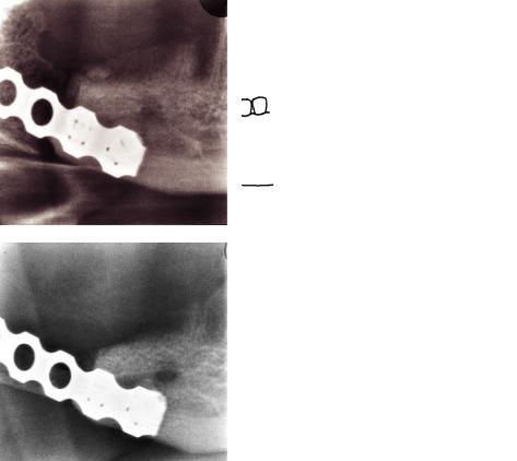
FIGURE 20A.3 An example of detailed narrow-beam radiography. The examination includes four different projections, which is helpful in the evaluation of bone structure details. This example shows the proximal part of a bone graft the day following surgery.
Imaging Sequence and Interpretation
The Upper Jaw
Before surgery, a Waters’ view may be complementary to the anthropomorphic measurement evaluations. Waters’ view provides an overview of the deformity. Preoperative management of complex cases require CT, and 3-D reconstruction is very valuable.4 A postoperative Waters’ view is often sufficient for the assessment of osteosynthesis plate location (Figure 20A.4), although in general plain films are of limited use in follow-up of the upper jaw.
a
b
FIGURE 20A.4 Waters’ view after surgery is sufficient to show the implant abutments in place. (Same patient as in Figure 20A.2). (b) A diagrammatic representation of (a).
20A. Radiographic Evaluation
The Lower Jaw, Corrective Surgery
Prior to operation, the anthropomorphic measurements are coordinated with a panoramic radiograph, Towne’s projection, and axial view to determine the status of the dentition and the shape of the mandible.
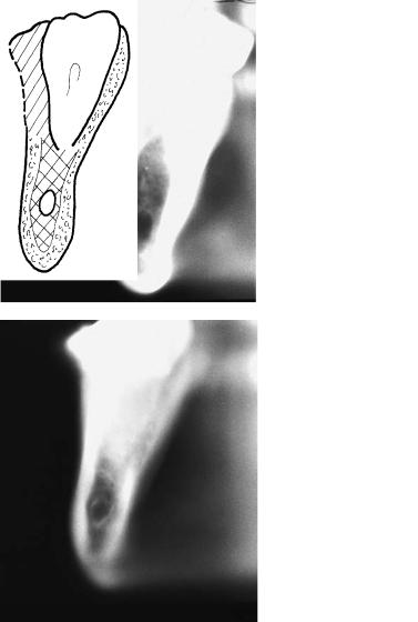
Cross-sectional multidirectional tomography of the planned osteotomy site is recommended to assess location of the mandibular canal and the form, height, and thickness of the mandible (Figure 20A.5).
a
c
213
The first follow-up examination is performed the day after surgery, and it should include a panoramic and a Towne’s projection. Positioning the patient for a submentovertex view causes considerable pain and discomfort and should be avoided in the early postoperative period. The osteotomy sites are then evaluated: amount of correction, location of fixation material, and any indications of unfavorable correction, including the temporomandibular joints.
To evaluate the healing process, a follow-up schedule of examinations at 1, 3, and 6 months is suitable, as long as the clin-
b
d
FIGURE 20A.5 (a) Cross-sectional tomography of the right lower jaw at the level of the distal molar area. The mandibular canal is clearly visible lingually. The patient was a 46-year-old woman with retrognathia. (b) A diagrammatic representation of (a). (c) Preoperative ex-
amination of a 26-year-old woman with prognathia. Cross-sectional tomography of the right molar area shows the mandibular canal, which is located centrally. The thickness of the lower jaw at the level of the canal is only 8 mm. (d) A diagrammatic representation of (c).
214
ical course is uneventful. If the first follow-up examination reveals inadequate correction or any indications of complication, the examination schedule is adjusted. In these situations, the examination can include detailed narrow-beam images as well as multidirectional tomography, with particular attention directed toward signs of infection and delayed union.
The Lower Jaw, Reconstructive Surgery
The preoperative examination should include at least a panoramic radiograph, Towne’s projection, and an axial view. Depending on the underlying lesion other examinations, such as detailed narrow-beam images, conventional tomography, or CT, may be obtained.10 The first follow-up examination is performed on the first postoperative day, and it should include a panoramic and Towne’s radiographs. The height of the bone graft is measured from the panoramic image, which will be
a
c
D. Hallikainen, C. Lindqvist, and A.-L. Söderholm
used as reference for further measurements. This is an exception to the general rule that measurements should not be taken from panoramic images.10,17
The magnification on a panoramic image is not constant, but varies in different parts of the image. This is remarkable, especially in the horizontal direction, where even a slight change in patient positioning has considerable influence on the horizontal dimensions.17 This variability is not as considerable in the vertical direction, so measurements from successive images of the same patient’s region of interest are sufficiently accurate to permit, for example, graft-height assessment (Figures 20A.6 and 20A.7).
The overall location of the reconstruction plate and screws are evaluated from the panoramic and Towne’s images. The second and third follow-up examinations are scheduled 2 weeks and 1 month after the operation. It is possible to recognize evidence of infection 2 weeks after surgery.18 Early
b
d
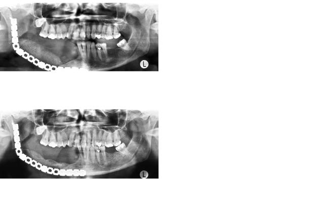
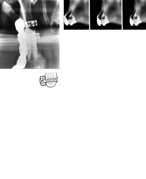
FIGURE 20A.6 (a) A panoramic image taken 2 days after graft surgery. The height of the graft can be measured in the vertical direction. (b) A diagrammatic representation of (a). (c) A panoramic image of the same patient 8 months after insertion of the graft. There
is moderate resorption of the graft, which has diminished in height. Good healing is seen at the medial end, but there is still a gap between graft and mandible in the angular area, indicating delayed healing. (d) A diagrammatic representation of (c).
20A. Radiographic Evaluation |
215 |
a |
b |
c |
d |
e |
f |
FIGURE 20A.7 (a) A panoramic image taken 3 days after graft surgery. Note height and density of the graft. (b) A diagrammatic representation of (a). (c) A panoramic image of the same patient 2 months later. The graft has diminished in height, and there is a marked radiolucent defect, indicating resorption within the graft. (d)
A diagrammatic representation of (c). (e) A panoramic image 8 months after graft surgery. The height of the graft is approximately one third of the original height, indicating ongoing and marked resorption, but no signs of infection. (f) A diagrammatic representation of (e).
216 |
D. Hallikainen, C. Lindqvist, and A.-L. Söderholm |
a |
b |
c |
d |
FIGURE 20A.8 (a) Example of massive graft resorption. A detailed image of the medial end of a bone graft on the day following surgery. The graft height corresponds to the mandible. (b) A diagrammatic representation of (a). (c) The same patient 4 months later. The graft
graft failure can be diagnosed 1 month postoperatively.10 In these examinations, a panoramic and Towne’s projection are complemented with detailed narrow-beam images (Figure 20A.8). Cross-sectional tomography is undertaken if the detailed images show excessive graft resorption or signs of infection (Figure 20A.9).
The schedule for further follow-up examinations depends on the findings at 1 month after surgery, with any signs of infection, significant graft resorption, or slow healing requiring closer follow-up. In nonvascularized grafts, some degree of bone resorption regularly appears, in which slight resorption (where the height of the graft diminishes 0% to 15% within the first 3 months) is a reliable sign of good healing.10
On the other hand, resorption exceeding 30% always indi-
has dimished in height; the upper border is visible through the holes in the plate. The resorption exceeds 30% and indicates graft failure.
(d) A diagrammatic representation of (c).
cates graft failure, and if this condition is recognized early, it can influence patient care and the timing of further treatment. Moderate graft resorption of 15% to 30% may appear for several reasons, but it always indicates the need for thorough and regular follow-up, and leads to more efficient treatment of these complications.
Infection appears as patchy bone loss, with blurring of the trabecular pattern and increased sclerosis, and detailed images are suitable for the interpretation of the signs of infection.18 Cross-sectional tomography is useful in discovering cortical resorption under the fixation plate, where some degree of resorption is often seen, although massive resorption usually indicates diminished stability. Screw loosening is easy to eval-
uate on cross-sectional images (Figure 20A.10).16
20A. Radiographic Evaluation |
217 |
a |
b |
c
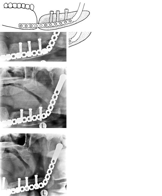
FIGURE 20A.9 (a) A detailed image in the posteroanterior direction of the condylar fragment shows two screws in good position. No signs of bone resorption. (b) A cross-sectional tomography of the
mandibular body area (same patient). Three consecutive cuts show the body screws in good position. (c) A diagrammatic representation of (a) and (b).
218 |
D. Hallikainen, C. Lindqvist, and A.-L. Söderholm |
a |
b |
c
FIGURE 20A.10 (a) A panoramic image of a 59-year-old patient shows a reconstruction plate and a vascular, fibular graft. There is a gap between the mandibular symphysis and the medial end of the graft. (b) Cross-sectional tomography of the symphyseal area demon-
Conclusion
Panoramic radiography, plain films, and multidirectional tomography are still valuable tools in examinations for reconstructive bone surgery of the mandible. The imaging procedure must be selected according to the specified diagnostic task, and good image quality is a necessity. Close collaboration between clinician and radiologist is essential for an optimal result.
References
1.Bowerman J, Huges L. Radiology of bone grafts. Radiol Clin North Am. 1975;13:67–77.
2.Murphey M. Imaging aspects of new techniques in orthopedic surgery. Radiol Clin North Am. 1994;32:201–225.
3.Ekestubbe A, Thilander A, Gröndahl K, et al. Absorbed doses
strates a gap between the plate and mandible. Only one screw is bicortical. These findings indicate loosening of the screws. (c) A diagrammatic representation of (a) and (b).
from computed tomography for dental implant surgery: comparison with conventional tomography. Dentomaxillofac Radiol. 1993;22:13–17.
4.Wolford L, Henry C. Preoperative and postoperative imaging evaluation of patients with maxillofacial deformities. Radiol Clin North Am. 1993;31:221–231.
5.Hallikainen D, Paukku P. Panoramic zonography. In: DelBalso A, ed. Maxillofacial Imaging. Philadelphia: WB Saunders; 1990:1–33.
6.Tammisalo E, Hallikainen D, Kanerva H, et al. Comprehensive oral x-ray diagnosis: scanora (R) multimodal radiography. A preliminary description. Dentomaxillofac Radiol. 1992;21:9–15.
7.Paukku P, Tötterman S, Hallikainen D, et al. Comparison of the visibility of the anatomical structures of the facial skeleton in panoramic zonography and linear tomography. Eur J Radiol. 1983;3:177–179.
8.Tammisalo T, Luostarinen T, Vähätalo K, et al. Comparison of periapical and detailed narrow-beam radiography for diagnosis
20A. Radiographic Evaluation
of periapical bone lesions. Dentomaxillofac Radiol. 1993;22: 183–187.
9.Tammisalo T, Vähätalo K, Luostarinen T, et al. Comparison of periapical and narrow-beam radiography for diagnosis of periodontal pathology. Dentomaxillofac Radiol. 1994;23:97–101.
10.Söderholm A, Hallikainen D, Lindqvist C. Radiologic followup of bone transplants to bridge mandibular continuity defects.
Oral Surg Oral Med Oral Pathol. 1992;73:253–261.
11.Hall R, DelBalso A, Carter L. Radiography of the sinonasal tract. In: DelBalso A, ed. Maxillofacial Imaging. Philadelphia: WB Saunders; 1990:139–207.
12.Littleton J. Tomography: Physical Principles and Clinical Applications. Baltimore: Williams & Wilkins; 1976:33–75.
13.Hallikainen D, Iizuka T, Lindqvist C. Cross-sectional tomography in evaluation of patients undergoing sagittal split osteotomy.
J Oral Maxillofac Surg. 1992;50:1269–1273.
219
14.Ekestubbe A, Gröndahl H. Reliability of spiral tomography with the Scanora (R) technique for implant planning. Clin Oral Implants Res. 1993;4:195–202.
15.Gröndahl K, Ekestubbe A, Gröndahl G. A multimodal unit for comprehensive dento-maxillofacial radiography. Dental Update. 1993;20:436–440.
16.Söderholm A, Hallikainen D, Lindqvist C. Long-term stability of two different mandibular bridging systems. Arch Otolaryngol Head Neck Surg. 1993;119:1031–1036.
17.Welander U, McDavid W, Tronje G. Theory of rotational panoramic radiography. In: Langland O, Langlais R, Morris C, eds. Principles and Practice of Panoramic Radiology. Philadelphia: WB Saunders; 1982:37–63.
18.Iizuka T, Lindqvist C, Hallikainen D, et al. Infection after internal fixation of mandibular fractures. A clinical and radiological study. J Oral Maxillofac Surg. 1991;49:585–593.