

- •Preface
- •Acknowledgments
- •Contents
- •Contributors
- •1. Introduction
- •2. Evaluation of the Craniomaxillofacial Deformity Patient
- •3. Craniofacial Deformities: Review of Etiologies, Distribution, and Their Classification
- •4. Etiology of Skeletal Malocclusion
- •5. Etiology, Distribution, and Classification of Craniomaxillofacial Deformities: Traumatic Defects
- •6. Etiology, Distribution, and Classification of Craniomaxillofacial Deformities: Review of Nasal Deformities
- •7. Review of Benign Tumors of the Maxillofacial Region and Considerations for Bone Invasion
- •8. Oral Malignancies: Etiology, Distribution, and Basic Treatment Considerations
- •9. Craniomaxillofacial Bone Infections: Etiologies, Distributions, and Associated Defects
- •11. Craniomaxillofacial Bone Healing, Biomechanics, and Rigid Internal Fixation
- •12. Metal for Craniomaxillofacial Internal Fixation Implants and Its Physiological Implications
- •13. Bioresorbable Materials for Bone Fixation: Review of Biological Concepts and Mechanical Aspects
- •14. Advanced Bone Healing Concepts in Craniomaxillofacial Reconstructive and Corrective Bone Surgery
- •15. The ITI Dental Implant System
- •16. Localized Ridge Augmentation Using Guided Bone Regeneration in Deficient Implant Sites
- •17. The ITI Dental Implant System in Maxillofacial Applications
- •18. Maxillary Sinus Grafting and Osseointegration Surgery
- •19. Computerized Tomography and Its Use for Craniomaxillofacial Dental Implantology
- •20B. Atlas of Cases
- •21A. Prosthodontic Considerations in Dental Implant Restoration
- •21B. Overdenture Case Reports
- •22. AO/ASIF Mandibular Hardware
- •23. Aesthetic Considerations in Reconstructive and Corrective Craniomaxillofacial Bone Surgery
- •24. Considerations for Reconstruction of the Head and Neck Oncologic Patient
- •25. Autogenous Bone Grafts in Maxillofacial Reconstruction
- •26. Current Practice and Future Trends in Craniomaxillofacial Reconstructive and Corrective Microvascular Bone Surgery
- •27. Considerations in the Fixation of Bone Grafts for the Reconstruction of Mandibular Continuity Defects
- •28. Indications and Technical Considerations of Different Fibula Grafts
- •29. Soft Tissue Flaps for Coverage of Craniomaxillofacial Osseous Continuity Defects with or Without Bone Graft and Rigid Fixation
- •30. Mandibular Condyle Reconstruction with Free Costochondral Grafting
- •31. Microsurgical Reconstruction of Large Defects of the Maxilla, Midface, and Cranial Base
- •32. Condylar Prosthesis for the Replacement of the Mandibular Condyle
- •33. Problems Related to Mandibular Condylar Prosthesis
- •34. Reconstruction of Defects of the Mandibular Angle
- •35. Mandibular Body Reconstruction
- •36. Marginal Mandibulectomy
- •37. Reconstruction of Extensive Anterior Defects of the Mandible
- •38. Radiation Therapy and Considerations for Internal Fixation Devices
- •39. Management of Posttraumatic Osteomyelitis of the Mandible
- •40. Bilateral Maxillary Defects: THORP Plate Reconstruction with Removable Prosthesis
- •41. AO/ASIF Craniofacial Fixation System Hardware
- •43. Orbital Reconstruction
- •44. Nasal Reconstruction Using Bone Grafts and Rigid Internal Fixation
- •46. Orthognathic Examination
- •47. Considerations in Planning for Bimaxillary Surgery and the Implications of Rigid Internal Fixation
- •48. Reconstruction of Cleft Lip and Palate Osseous Defects and Deformities
- •49. Maxillary Osteotomies and Considerations for Rigid Internal Fixation
- •50. Mandibular Osteotomies and Considerations for Rigid Internal Fixation
- •51. Genioplasty Techniques and Considerations for Rigid Internal Fixation
- •52. Long-Term Stability of Maxillary and Mandibular Osteotomies with Rigid Internal Fixation
- •53. Le Fort II and Le Fort III Osteotomies for Midface Reconstruction and Considerations for Internal Fixation
- •54. Craniofacial Deformities: Introduction and Principles of Management
- •55. The Effects of Plate and Screw Fixation on the Growing Craniofacial Skeleton
- •56. Calvarial Bone Graft Harvesting Techniques: Considerations for Their Use with Rigid Fixation Techniques in the Craniomaxillofacial Region
- •57. Crouzon Syndrome: Basic Dysmorphology and Staging of Reconstruction
- •58. Hemifacial Microsomia
- •59. Orbital Hypertelorism: Surgical Management
- •60. Surgical Correction of the Apert Craniofacial Deformities
- •Index
56
Calvarial Bone Graft Harvesting Techniques: Considerations for Their Use with Rigid Fixation Techniques in the Craniomaxillofacial Region
John L. Frodel, Jr.
As reconstruction of the craniomaxillofacial (CMF) skeleton |
During growth and development, the calvarium eventually |
has evolved in the treatment of traumatic, oncologic, con- |
consists of distinct cortical bone layers (the inner and outer |
genital, and aesthetic deformities, so have the requirements |
cortices) with a spongy cancellous layer (the diploe) in be- |
for various restorative materials. The hardware for rigid in- |
tween. Tightly adhering to the undersurface of the calvarium |
ternal fixation now permits the necessary structural support |
is the dura. The inner cortex of the calvarium is imprinted |
in such reconstructive situations, often in conjunction with |
with various vascular structures such as the midline sagittal |
bone grafts. While iliac crest remains the principal source used |
sinus, which is approximately 1 cm in width. Another im- |
for free bone grafting in the mandible, calvarial bone grafts |
portant aspect of the calvarium, which becomes manifest dur- |
have become the material of choice for bony reconstruction |
ing consideration for calvarial bone graft harvesting, is the re- |
of all other craniomaxillofacial defects (where nonvascular- |
gion known as the temporal line (the superior attachment of |
ized bone is adequate). |
the temporalis muscle). This is significant because lateral and |
In this chapter, the embryology and surgical anatomy as |
inferior to this line the skull becomes quite thin. The other |
well as various graft harvest principles and techniques are re- |
vital landmarks include the various sagittal, coronal, lamb- |
viewed. Principles for the fixation of bone grafts are dis- |
doid sagittal, and squamosal sutures. These represent sites of |
cussed, followed by cases illustrative of these techniques. |
fusion between the two cortices of originally distinct skull |
|
bones and, accordingly, are without diploic space. |
Embryology and Surgical Anatomy |
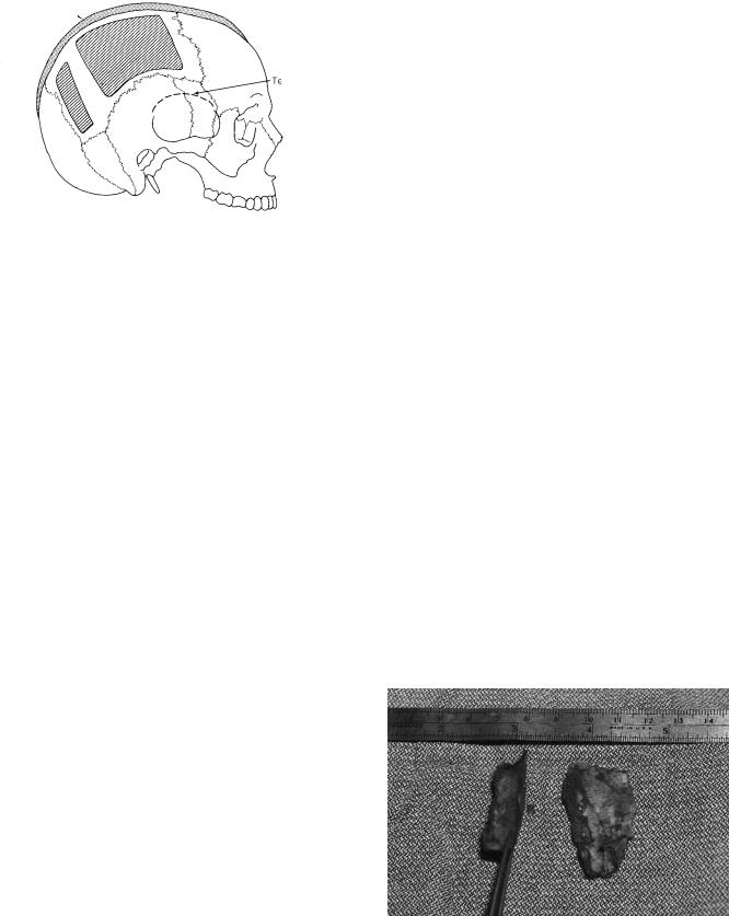
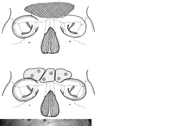
With these anatomic regions in mind, “danger” areas exist |
for consideration in site selection for calvarial bone graft har- |
|
|
vesting (Figure 56.1). These zones represent sites at risk for |
When considering the type of bone (i.e., calvarium) for use |
intracranial exposure and injury, and include the midline (the |
in CMF reconstruction, the embryological origin of the graft |
sagittal sinus underlies the sagittal suture) and the temporal |
material takes on great importance. When considering the use |
line inferiorly, as well as the various embryological suture re- |
of calvarium for craniomaxillofacial reconstruction, the em- |
gions where the bone tends to be quite thin. Other variable |
bryological origin of the bone becomes very important.1–6 considerations include the presence of transcortical emissary
Embryologically, the skull consists of three divisions: chon- |
veins, subcortical vessels, and arachnoid plexuses, which can |
drocranium, desmocranium, and the appendicular or visceral |
exist within the cortical portion of the calvarium. |
portion. The chondrocranium is cartilaginous and includes the |
Another factor for consideration is the unpredictability of |
skull base, as well as the nasal and optic capsules. The vis- |
the skull thickness. Pensler and McCathy studied 200 cadaver |
ceral portion is derived from the branchial arches, and de- |
skulls, measuring various aspects of the parietal and occipi- |
velops into the various cartilaginous skeletal appendices. Fi- |
tal regions.8 Their study found that the thickest bone was con- |
nally, the desmocranium is membranous and consists of |
sistently noted to exist in the parietal region, that male cal- |
portions of the temporal, sphenoid, occipital, nasal, maxillary, |
varia tends to be slightly thicker than that of females, and that |
and zygomatic bones, including a significant portion of the |
age was not a significant factor. It is of particular note that |
mandible. This embryological origin is important as studies |
the skull is generally fully developed by 8 years of age but |
have demonstrated that bone grafts of membranous bone ori- |
continues to thicken until about 20 years of age. To summa- |
gin (i.e., calvarium) resorb significantly less than endochon- |
rize the anatomic considerations, calvarial bone grafts are best |
dral bone (i.e., iliac crest), although a recent study by Phillips |
harvested in the parietal region (an area approximately 8 |
and Rahn has suggested that rigid fixation reduces the amount |
10 cm, where the calvarium is thickest and the “danger” ar- |
of resorption with endochondral bone.7 |
eas (the midline and temporal regions) are avoided. |
700
56. Calvarial Bone Graft Harvesting Techniques
Sagittal sinus
Temporal line
FIGURE 56.1 The “danger” areas of the calvarium. (From Frodel,12 with permission)
Calvarial Bone Graft
Harvesting and Techniques
In the preparation for harvest of a calvarial bone graft, several considerations are necessary before performing this procedure. First, one must consider requirements of the recipient site with respect to bone thickness and curvature.9,10 For example, defects that require curved grafts (e.g., orbit, malar region) may better be harvested as horizontal strips over the temporoparietal region. Conversely, defects requiring straight grafts (e.g., nasal dorsum) should be harvested in the occipitoparietal region.
Graft length and width vary with the reconstructive needs, but rarely is a graft needed that is longer than 5 to 6 cm or wider than 1.5 to 2 cm. Attempts to harvest grafts larger than this often result in fracture of the bone graft during removal, as well as increasing the risk for intracranial exposure. Accordingly, the surgeon should consider the use of multiple small grafts whenever possible. Another consideration is access to proper instrumentation. It is extremely important to utilize a sharp osteotome. The author prefers the use of a thin, curved osteotome that is approximately 1 cm wide. It is important that this is kept sharpened to provide the utmost control during the harvesting process.
Regarding surgical approaches, if a coronal incision has been made to approach the upper aspect of the craniomaxillofacial skeleton, the posterior margin of this incision can be elevated in a subperiosteal plane to expose the entire anterior and midportions of the parietal bone. If such an incision has not been made, a direct horizontal incision can be made in the hair-bearing region over the parietal bone. In patients with alopecia, this incision should be made within the hair-bearing region, followed by medial retraction to expose the necessary donor site. It should be noted that hair is rarely shaved in preparation for such graft harvesting, unless lacerations are present, for example, in trauma cases.
701
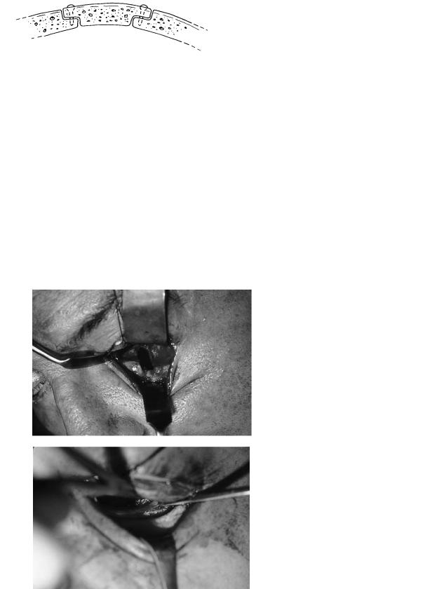
Techniques for calvarial bone graft harvesting can be divided into three categories: partial-thickness outer cortex grafts, full-thickness outer cortex grafts, and bicortical or inner cortex grafts. Partial-thickness outer cortex grafts are commonly harvested in children. In this technique, an osteotome is used to elevate a curl of outer cortical bone (also called a “potato chip” graft), which is only a partial thickness of the outer cortical bone. Such bone graft harvesting techniques are ideal in children of approximately 4 to 8 years of age, as these patients have very soft bone, and the graft can usually be obtained without significant fracturing (Figure 56.2). However, this technique is fraught with graft fragmentation in adult patients. Accordingly, the use of such bone is limited to very small defects or the packing of larger defects.
Perhaps the most common type of calvarial graft harvested is the removal of the outer cortex in its entirety (i.e., leaving the full inner cortex intact). The basic principle is to separate the inner and outer cortices without penetration of the inner aspect of the calvarium, with its attendant sequelae of dural exposure. The initial step is to define, if possible, the diploic layer after outlining proposed bone grafts. It should be noted that some patients do not have a distinct diploic layer, and this should be considered at all times. However, the harvesting of the graft is usually initiated with the use of a cutting bur along at least one side of the graft area (Figure 56.3). A variety of techniques can then be utilized for further elevation of the outer cortex graft.9,11,12 In general, either an osteotome alone is used to elevate the graft, or on occasion, a sagittal or reciprocating saw may be utilized.
Before elevation, the graft should be outlined using a small drill bit or side-cutting bur. If multiple bone grafts are harvested, this outlining should waste as little bone as possible so as to use the calvarium efficiently (Figure 56.4). In using either the osteotome or saw technique, it is of critical importance that the osteotome or saw blade proceeds parallel to the inner and outer cortices within the diploic space. This can only take place if an adequate “trough” has been created at
FIGURE 56.2 Clinical example of a split outer table (“potato chip” graft).

702 |
J.L. Frodel, Jr. |
a
b
FIGURE 56.3 Diagram depicting the phases of calvarial bone graft harvest, including creation of a wide sloping trough with a large cutting bur and outlining of the various bone grafts with a smaller bur (Top diagram). Subsequent elevation then is undertaken with an osteotome (middle diagram) or sagittal saw (lower diagram). (From Frodel,12 with permission)
the advancing front of the harvest site. If such a trough has not been created, the osteotome or saw blade will likely be misdirected and enter through or fracture the inner cortex (Figure 56.5). The major advantage of using an osteotome for the complete harvest of the outer cortex graft is that no bone is wasted, as it is in using a saw technique. However, if minimal or no dipolic space exists, the authors found the sagittal saw technique provides greater control and safety. Regardless of the technique, however, risk always exist for entry through the inner cortex, with possible injury to the underlying dura. It should be noted that with either technique, diploic vessels may be encountered and the use of bone wax may be indicated.
Following harvest of the outer cortex bone graft, the surrounding edges of the donor site are contoured with a large cutting bur to minimize the outer deformity. It is important to counsel the patient perioperatively that they will have a slightly flattened area in the region of the donor site. However, obvious ridges are easily avoidable. Another method for avoidance of such a deformity is by reconstruction of the donor site with various alloplastic materials such as Medpor or hydroxyapatite.
In some situations, the use of inner cortex calvarial bone is desired. This can be a technique of choice when a cra-
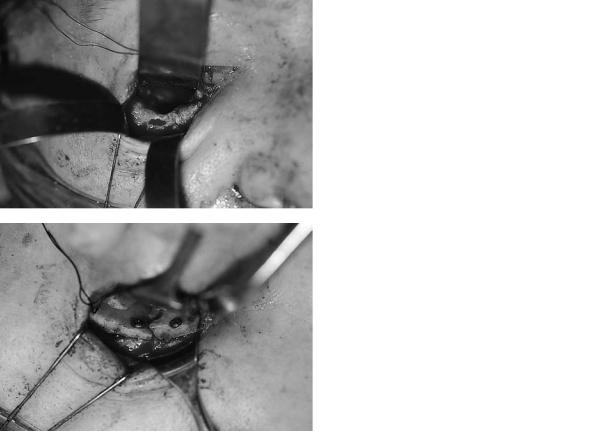
FIGURE 56.4 Clinical example of a full-thickness outer cortex graft.
(a) The appearance of the bed after the harvest of two previous bone grafts with one bone graft harvest remaining. (b) Multiple bone grafts harvested from the same patient.
FIGURE 56.5 Diagram of problems in calvarial bone harvesting. (A) Proper technique with proper angulation of the osteotome into the diploic space, parallel to the inner and outer cortices. Note the wide trough that allows proper direction of the osteotome. (B) Inadequate placement of a osteotome caused by inadequate trough or creation. (From Frodel,12 with permission)

56. Calvarial Bone Graft Harvesting Techniques |
703 |
FIGURE 56.6 Diagram of the use of a craniotomy bone flap, which was then split with a saw and osteotome into an inner and outer table. (From Frodel,12 with permission)
niotomy has been performed, so that bone from the inner aspect of this bone flap can be harvested. In such situations, a sagittal saw and osteotome may be used to separate the inner and outer calvarial bone tables (Figures 56.6 and 56.7). The inner portion of this bone flap can then be utilized for grafting material, followed by replacement of the outer cortex to its original position at the end of the operation. Some surgeons believe that this is the ideal method and use it liberally, even when an intracranial procedure is not performed. The author does not think that in general it is indicated unless a craniotomy has been performed.
Bone Graft Harvest Complications
Despite adherence to these basic principles of bone graft harvesting, complications occur. The most common complication is that of donor site deformity although, as mentioned, this can be minimized by careful contouring of the donor site edges. Another common relative complication is that of undesired fracture of the bone graft during harvest. While this cannot always be avoided, the key to obtaining an intact graft for the surgeon is to be patient during the elevation process, because any forceful elevation of the saw or osteotome will lead to premature fracturing of the grafts. Dural exposure, an infrequent common complication, can be avoided by careful elevation within the diploic space. Occasionally, dura will be exposed during the elevation process, and it is important to identify when the inner cortex has been violated. When this occurs, it is not necessary to discontinue the graft harvesting procedure, although careful attention must be directed toward reelevation
FIGURE 56.7 Clinical example of a craniotomy bone flap with multiple grafts harvested from the inner cortex.
in the diploic plane. If the graft is elevated and there is evidence not only of dural exposure but also of dural tear, the dural tear must be completely exposed by the use of a rongeur to further remove inner cortical bone. The tear can then be repaired directly and, if necessary, a graft of temporalis fascia may be utilized. Neurosurgical consultation is generally appropriate in such situations. There have been rare reports of intracranial bleeding following bone graft harvesting. Change of neurologic status intraoperatively or postoperatively should acutely raise the suspicion of such an injury. Fortunately, such complications seem to be extremely uncommon.
Rigid Fixation Considerations
Once the appropriate shape and number of calvarial bone grafts are obtained, they can now be placed in the recipient bed. It is the author’s opinion that preparation of the recipient bed is of critical importance to the long-term survival of the bone graft. While calvarial bone grafts in the upper maxillofacial skeleton tend to undergo minimal resorption in most situations, this remains unpredictable and steps should be taken to maximize the environment for optimal graft “take.” Nonvascularized bone graft healing is by “creeping substitution” when it is in adequate contact with underlying viable bone, as an onlay graft. In many other situations, bone graft survival occurs similarly to an alloplast, without replacement of the grafted material with new bone. This form of nonsubstituting graft survival is one feature of calvarial bone grafting that appears to be unique. It is also recognized that grafts with limited contact with healthy underlying bone and nonrigidly fixated have a greater propensity toward partial or complete resorption. Accordingly, the recipient bone should be prepared whenever possible by perforation to a bleeding cancellous space so that the bone graft may overlap this area (Figure 56.8). This is particularly important when a portion of the graft will not be in contact with healthy underlying
704
FIGURE 56.8 Diagram of inlay-overlay technique. Both the recipient and the defect in the bone graft are precontoured to allow for an inset of the bone graft with subsequent lag screw fixation. (From Frodel and Marentette,13 with permission)
bone, as in reconstruction of an orbital rim, maxillary buttress, or zygomatic arch.
Fixation techniques vary depending on the situation and it is rare that hardware is not utilized, but this is occasionally the case when using bone grafts for orbital reconstruction. Miniplates and microplates are often employed, but these have several disadvantages. They do not provide absolute stability and, accordingly, cannot allow optimal environment for adequate bone healing. Although these plates may be palpable through the overlying skin, the use of small plates is still im-
a
b
J.L. Frodel, Jr.
portant in certain situations. The author’s preference is to use the lag screw fixation technique whenever possible (Figure 56.8).13 This technique requires the adequate preparation (perforation) of an underlying recipient bone bed and allows for absolute rigid fixation of the bone graft. An additional benefit is that the implant device is not palpable through the skin because it has been countersunk into the bone graft. Therefore, whenever possible, lag screw fixation of calvarial bone grafts to the maxillofacial skeleton is utilized.
Calvarial Bone Grafting Indications
Calvarial bone grafts are indicated in the reconstruction of a large variety of bony defects, depressions, and deformations that can exist from a variety of conditions secondary to trauma, oncologic resection, or congenital deformities. Occasionally, they are used in various aesthetic maxillofacial procedures. Clinical examples are now presented to demonstrate basic operative principles and the utilization of bone grafts for various defects of the craniomaxillofacial skeleton.
FIGURE 56.9 Left orbital floor defect with bone graft positioning (no fixation). (a) Left orbitial floor defect. (b) Placement of curved calvarial bone graft over left orbital floor defect without fixation.
56. Calvarial Bone Graft Harvesting Techniques
Case 1
A left orbital defect is presented in Figure 56.9a. Figure 56.9b demonstrates the placement of a curved bone graft without fixation into this defect. The use of bone grafts within the orbit without fixation techniques is a common procedure.
Case 2
Figure 56.10 shows a large right orbital defect in which multiple calvarial bone grafts have been placed. Because of the presence of an anterior ledge of bone, the lag screw fixation can be utilized to further cantilever the bone grafts superiorly and medially to restore the normal shape of the orbital cavity.
Case 3
Figure 56.11 shows a right infraorbital rim defect after zygomatic repositioning. A miniplate has been placed to sta-
a
b
705
bilize the medial and lateral segments of the orbital rim so as to reestablish the malar eminence (Figure 56.11a). After stabilization of other locations, the recipient site is prepared by contouring the residual bone adjacent to the defect to allow for inset of a contoured calvarial bone graft. This is then fixated into position as shown in Figure 56.11b.
Case 4
A left lateral maxillary buttress defect (Figure 56.12a) is shown after repositioning of the zygomatic segment with an L-shaped miniplate. A defect is noted in the maxillary buttress region. Figure 56.12b demonstrates placement of a calvarial bone graft after loosening of the screws in the plate, wedging of the bone graft under the plate, and the subsequent retightening of the plate to stabilize the bone graft into position.
FIGURE 56.10 Right orbital floor defect with bone graft reconstruction using lag screw fixation: (a) Right orbital floor defect. (b) Placement of two bone grafts over left orbital floor defect with lag screw fixation.
706 |
J.L. Frodel, Jr. |
a
b
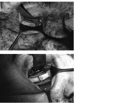
FIGURE 56.11 Right infraorbital rim defect with onlay bone graft. (a) Right infraorbital rim defect temporarily bridged with a miniplate.
(b) Inset onlay bone graft technique with lag screw fixation of right infraorbital rim defect.
56. Calvarial Bone Graft Harvesting Techniques |
707 |
a
b
FIGURE 56.12 Left lateral zygomaticomaxillary buttress defect. (a) Left lateral zygomaticomaxillary buttress defect bridged with miniplate.
(b) Wedged bone graft with good bony contact under miniplate of left lateral zygomaticomaxillary buttress defect.

708
Case 5
Figure 56.13a shows a larger left maxillary buttress defect. Figure 56.13b demonstrates placement of a large calvarial bone graft that is contoured in a concave shape and secured superiorly and inferiorly by lag screw fixation.
J.L. Frodel, Jr.
cerns for excessive lateral projection by placement of an overlay bone graft, the residual bone adjacent to the defect is trimmed from the undersurface, allowing for placement of an appropriately contoured bone graft. This is subsequently fixated by the lag screw technique.
Case 6
Pictured and diagrammed (Figure 56.14) is a right zygomatic arch defect after zygomatic repositioning. Because of the con-
a
b
Case 7
A large calvarial defect is shown [Figure 56.15(a)] following a traumatic injury, which encompasses the entire right frontal
FIGURE 56.13 Large left anterolateral maxillary defect with onlay bone graft reconstruction. (a) Left anterolateral maxillary bone defect.
(b) Calvarial onlay bone graft with lag screw fixation reconstruction.

a
b
c
FIGURE 56.14 Diagrams demonstrating
(a) right zygomatic defect and (b,c) placement of a calvarial bone graft using an underlay technique stabilized by lag screw fixation.

710 |
J.L. Frodel, Jr. |
a
b
FIGURE 56.15 Large right frontal cranial and supraorbital rim defect with calvarial bone graft reconstruction. (a) Large right frontal cranial and supraorbital rim defect. (b) Multiple calvarial bone grafts
with miniplate fixation for reconstruction of large right frontal cranial and supraorbital rim defect.
56. Calvarial Bone Graft Harvesting Techniques |
711 |
a
b
FIGURE 56.16 Collapse of anterior frontal bone after frontal sinus infection with calvarial bone graft reconstruction. (a) Anterior frontal bone defect. (b) Following frontal sinus debridement, reconstruction
cranial and supraorbital rim and roof region. Figure 56.15b shows reconstruction of this defect using multiple calvarial bone grafts and miniplate fixation.
of anterior frontal bone with multiple calvarial bone grafts using lag screw fixation.
orbit and stabilized with lag screw fixation. Resorbable screws may be used in these circumstances with less concern for hardware removal or migration.14,15
Case 8
This case demonstrates loss of the anterior table of the frontal sinus with a subsequent frontal deformity (Figure 56.16). After removal of residual sinus disease and burring down of the bone, multiple bone grafts are placed and stabilized by lag screw fixation. Contouring was then performed to reconstruct the normal frontal orbital shape.
Case 9
Pictured and diagrammed (Figure 56.17) is a large anterior cranial-based defect. As this connects with the nasopharynx, this defect is reconstructed with two calvarial bone grafts placed onto the residual anterior fossa floor and roof of the
Summary
In conclusion, calvarial bone grafting provides an excellent tool in the armamentarium for craniomaxillofacial reconstruction. Key considerations include having proper equipment as well as patience during graft harvesting, maintaining the osteotome or saw position in the space between the inner and outer cortices of the calvarium, preparation of the recipient bed after selection of the appropriately shaped bone graft, and the use of rigid internal fixation utilizing the lag screw technique whenever possible. Resorbable screws may be used when adequate stabilization can be achieved, avoiding the sequelae of screw head palpation from graft resorption, or the need for hardware removal.14,15

712 |
J.L. Frodel, Jr. |
a
b
FIGURE 56.17 Large anterior cranial fossa defect following a gunshot wound with calvarial bone graft reconstruction. (a) Anterior cranial fossa defect. (b) Reconstruction of anterior cranial fossa floor defect with two calvarial bone grafts using a lag screw fixation.
References
1.Smith ID, Abramson M. Membranous vs. endochondral bone autografts. Arch Otolaryngol Head Neck Surg. 1983;99:203– 205.
2.Zins JE, Whitaker LA. Membranous vs. endochrondral bone grafts: implications for craniofacial reconstruction. Plast Reconstr Surg. 1985;76:510–514.
3.Kusiak JF, Zins JE, Witaker LA. The early revascularization of membranous bone. Plast Reconstr Surg. 1985:76:510–514.
4.Hardesty RA, Marsh JL. Craniofacial onlay bone grafting: a prospective evaluation of graft morphology, orientation, and embryologic origin. Plast Reconstr Surg. 1990;85:5–15.
5.Moore KI. The Developing Human. 2nd ed. Philadelphia: WB Saunders; 1977:307–309.
6.Craft PD, Sargent LA. Membranous bone healing and techniques in calvarial bone grafting. Clin Plast Surg. 1989;16:11– 19.
7.Phillips JH, Rahn BA. Fixation effects on membranous and endochondral onlay bone-graft resorption. Plast Reconstr Surg. 1988;82:872–877.
8.Pensler J, McCarthy JC. The calvarial donor site: an anatomic study in cadavers. Plast Reconstr Surg. 1985;75:648–651.
9.Powell NB, Riley, RW. Cranial bone grafting in facial aesthetic and reconstructive contouring. Arch Otolaryngol Head Neck Surg. 1987;Jul;113(7):713–719.
10.Sheen JH. A change in the site for cranial bone harvesting.
Prospect Plast Surg. 1990;4:48–57.
11.Frodel JL, Marentette LJ, Quatela VC, Weinstein GS. Calvarial bone graft harvest: techniques, considerations, and morbidity. Arch Otolaryngol Head Neck Surg. 1993;119:17–23.
12.Frodel JL. Complications of bone grafting. In: Eisele DW, ed.
Complications in Head and Neck Surgery. St. Louis: CV Mosby; 1993:773–784.
13.Frodel JL, Marentette LJ. Lag screw fixation in the upper craniomaxillofacial skeleton. Arch Otolaryngol Head Neck Surg.
1993;119:297–304.
14.Kurpad SN, Goldstein JA, Cohen AR. Bioresorbable fixation for congenital pediatric craniofacial surgery: a 2 year followup. Pediatr Neurosurg. 2000;33:306–310.
15.Pensler JM. Role of resorbable plates and screws in craniofacial surgery. J Craniofac Surg. 1997;8:129–134.