

10.5 Entities and Architectures
The highest-level VHDL construct is the design file [VHDL LRM11.1]. A design file contains design units that contain one or more library units. Library units in turn contain: entity, configuration, and package declarations (primary units); and architecture and package bodies (secondary units).
design_file ::=
{library_clause|use_clause} library_unit {{library_clause|use_clause} library_unit}
library_unit ::= primary_unit|secondary_unit primary_unit ::=
entity_declaration|configuration_declaration|package_declaration secondary_unit ::= architecture_body|package_body
Using the written language analogy: a VHDL library unit is a "book," a VHDL design file is a "bookshelf," and a VHDL library is a collection of bookshelves. A VHDL primary unit is a little like the chapter title and contents that appear on the first page of each chapter in this book and a VHDL secondary unit is like the chapter contents (though this is stretching our analogy a little far).
I shall describe the very important concepts of entities and architectures in this section and then cover libraries, packages, and package bodies. You define an entity, a black box, using an entity declaration [VHDL LRM1.1]. This is the BNF definition:
entity_declaration ::= entity identifier is
[generic (formal_generic_interface_list);] [port (formal_port_interface_list);] {entity_declarative_item}
[begin
{[label:] [postponed] assertion ;
|[label:] [postponed] passive_procedure_call ; |passive_process_statement}]
end [entity] [entity_identifier] ;
The following is an example of an entity declaration for a black box with two inputs and an output:
entity Half_Adder is
port (X, Y : in BIT := '0'; Sum, Cout : out BIT); -- formals
end;
Matching the parts of this code with the constructs in BNF [10.7] you can see that the identifier is Half_Adder and that (X, Y: in BIT := '0'; Sum, Cout: out BIT) corresponds to (port_interface_list) in the BNF. The ports X, Y, Sum, and Cout are formal ports or formals. This particular entity Half_Adder does not use any of the other optional constructs that are legal in an entity declaration.
The architecture body [VHDL LRM1.2] describes what an entity does, or the contents of the black box (it is architecture body and not architecture declaration).
architecture_body ::=
architecture identifier of entity_name is
{block_declarative_item} begin
{concurrent_statement}
end [architecture] [architecture_identifier] ;
For example, the following architecture body (I shall just call it an architecture from now on) describes the contents of the entity Half_Adder :
architecture Behave of Half_Adder is
begin Sum <= X xor Y; Cout <= X and Y; end Behave;
We use the same signal names (the formals: Sum , X , Y , and Cout ) in the architecture as we use in the entity (we say the signals of the "parent" entity are visible inside the architecture "child"). An architecture can refer to other entity-architecture pairs--so we can nest black boxes. We shall often refer to an entity-architecture pair as entity(architecture). For example, the architecture Behave of the entity Half_Adder is Half_Adder(Behave).
Why would we want to describe the outside of a black box (an entity) separately from the description of its contents (its architecture)? Separating the two makes it easier to move between different architectures for an entity (there must be at least one). For example, one architecture may model an entity at a behavioral level, while another architecture may be a structural model.
A structural model that uses an entity in an architecture must declare that entity and its interface using a component declaration
as follows [VHDL LRM4.5]:
component_declaration ::= component identifier [is]
[generic (local_generic_interface_list);] [port (local_port_interface_list);]
end component [component_identifier];
For example, the following architecture, Netlist , is a structural version of the behavioral architecture, Behave :
architecture Netlist of Half_Adder is
component MyXor port (A_Xor,B_Xor : in BIT; Z_Xor : out BIT); end component; -- component with locals
component MyAnd port (A_And,B_And : in BIT; Z_And : out BIT); end component; -- component with locals
begin
Xor1: MyXor port map (X, Y, Sum); -- instance with actuals
And1 : MyAnd port map (X, Y, Cout); -- instance with actuals
end;
Notice that:
●We declare the components: MyAnd, MyXor and their local ports (or locals): A_Xor, B_Xor, Z_Xor, A_And,
B_And, Z_And.
● We instantiate the components with instance names: And1 and Xor1.
● We connect instances using actual ports (or actuals): X, Y , Sum , Cout.
Next we define the entities and architectures that we shall use for the components MyAnd and MyXor . You can think of an entity-architecture pair (and its formal ports) as a data-book specification for a logic cell; the component (and its local ports) corresponds to a software model for the logic cell; and an instance (and its actual ports) is the logic cell.
We do not need to write VHDL code for MyAnd and MyXor ; the code is provided as a technology library (also called an ASIC vendor library because it is often sold or distributed by the ASIC company that will manufacture the chip--the ASIC vendor--and not the software company):
-- These definitions are part of a technology library: entity AndGate is
port (And_in_1, And_in_2 : in BIT; And_out : out BIT); -- formals
end;
architecture Simple of AndGate is
begin And_out <= And_in_1 and And_in_2;
end;
entity XorGate is
port (Xor_in_1, Xor_in_2 : in BIT; Xor_out : out BIT); -- formals
end;
architecture Simple of XorGate is
begin Xor_out <= Xor_in_1 xor Xor_in_2;
end;
If we keep the description of a circuit's interface (the entity ) separate from its contents (the architecture ), we need a way to link or bind them together. A configuration declaration [VHDL LRM1.3] binds entities and architectures.
configuration_declaration ::=
configuration identifier of entity_name is
{use_clause|attribute_specification|group_declaration} block_configuration
end [configuration] [configuration_identifier] ;
An entity-architecture pair is a design entity. The following configuration declaration defines which design entities we wish to use and associates the formal ports (from the entity declaration) with the local ports (from the component declaration):
configuration Simplest of Half_Adder is use work.all;
for Netlist
for And1 : MyAnd use entity AndGate(Simple)
port map -- association: formals => locals
(And_in_1 => A_And, And_in_2 => B_And, And_out =>
Z_And);
end for;
for Xor1 : MyXor use entity XorGate(Simple) port map
(Xor_in_1 => A_Xor, Xor_in_2 => B_Xor, Xor_out => Z_Xor);
end for;
end for;
end;
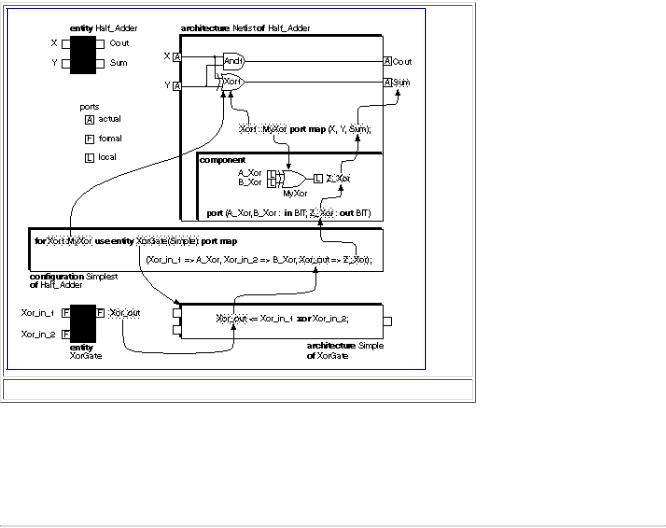
Figure 10.1 diagrams the use of entities, architectures, components, and configurations. This figure seems very complicated, but there are two reasons that VHDL works this way:
●Separating the entity, architecture, component, and configuration makes it easier to reuse code and change libraries. All we have to do is change names in the port maps and configuration declaration.
●We only have to alter and reanalyze the configuration declaration to change which architectures we use in a model--giving us a fast debug cycle.
You can think of design units, the analyzed entity-architecture pairs, as compiled object-code modules. The configuration then determines which object-code modules are linked together to form executable binary code.
You may also think of an entity as a block diagram, an architecture for an entity a more detailed circuit schematic for the block diagram, and a configuration as a parts list of the circuit components with their part numbers and manufacturers (also known as a BOM for bill of materials, rather like a shopping list). Most manufacturers (including the U.S. DoD) use schematics and BOMs as control documents for electronic systems. This is part of the rationale behind the structure of VHDL.
10.6 Packages and Libraries
After the VHDL tool has analyzed entities, architectures, and configurations, it stores the resulting design units in a library. Much of the power of VHDL comes from the use of predefined libraries and packages. A VHDL design library [VHDL LRM11.2] is either the current working library (things we are currently analyzing) or a predefined resource library (something we did yesterday, or we bought, or that came with the tool). The working library is named work and is the place where the code currently being analyzed is stored. Architectures must be in the same library (but they do not have to be in the same physical file on disk) as their parent entities.
You can use a VHDL package [VHDL LRM2.5-2.6] to define subprograms (procedures and functions), declare special types, modify the behavior of operators, or to hide complex code. Here is the BNF for a package declaration:
package_declaration ::= |
|
|
package identifier is |
|
|
{subprogram_declaration |
| type_declaration |
| subtype_declaration |
| constant_declaration |
| signal_declaration |
| file_declaration |
| alias_declaration |
| component_declaration |
|
| attribute_declaration | attribute_specification | disconnection_specification | use_clause
| shared_variable_declaration | group_declaration | group_template_declaration}
end [package] [package_identifier] ;
You need a package body if you declare any subprograms in the package declaration (a package declaration and its body do not have to be in the same file):
package_body ::= |
|
|
package body package_identifier is |
|
|
{subprogram_declaration |
| subprogram_body |
|
| type_declaration |
| subtype_declaration |
|
| constant_declaration |
| file_declaration |
| alias_declaration |
| use_clause
| shared_variable_declaration | group_declaration | group_template_declaration}
end [package body] [package_identifier] ;
To make a package visible [VHDL LRM10.3] (or accessible, so you can see and use the package and its contents), you must include a library clause before a design unit and a use clause either before a design unit or inside a unit, like this:
library MyLib; -- library clause
use MyLib.MyPackage.all; -- use clause
-- design unit (entity + architecture, etc.) follows:
The STD and WORK libraries and the STANDARD package are always visible. Things that are visible to an entity are visible to its architecture bodies.
10.6.1 Standard Package
The VHDL STANDARD package [VHDL LRM14.2] is defined in the LRM and implicitly declares the following implementation dependent types: TIME , INTEGER , REAL . We shall use uppercase for types defined in an IEEE standard package. Here is part of the STANDARD package showing the explicit type and subtype declarations:
package Part_STANDARD is type BOOLEAN
is (FALSE, TRUE); type BIT is ('0', '1');
type SEVERITY_LEVEL
is (NOTE, WARNING, ERROR, FAILURE); subtype NATURAL
is INTEGER range 0 to INTEGER'HIGH; subtype POSITIVE
is INTEGER range 1 to INTEGER'HIGH; type BIT_VECTOR
is array (NATURAL range <>) of BIT; type STRING
is array (POSITIVE range <>) of CHARACTER;
-- the following declarations are VHDL-93 only:
attribute FOREIGN: STRING; -- for links to other languages subtype DELAY_LENGTH is TIME range 0 fs to TIME'HIGH;
type FILE_OPEN_KIND is (READ_MODE,WRITE_MODE,APPEND_MODE); type FILE_OPEN_STATUS is (OPEN_OK,STATUS_ERROR,NAME_ERROR,MODE_ERROR);
end Part_STANDARD;
Notice that a STRING array must have a positive index. The type TIME is declared in the STANDARD package as follows:
type TIME is range implementation_defined |
-- and |
varies |
with software |
|
||
units fs; ps = |
1000 fs; ns = |
1000 |
ps; us |
= 1000 |
ns; ms = 1000 |
us; |
sec = 1000 ms; |
min = 60 sec; |
hr = |
60 min; end units; |
|
||
The STANDARD package also declares the function now that returns the current simulation time (with type TIME in VHDL-87 and subtype DELAY_LENGTH in VHDL-93).
In VHDL-93 the CHARACTER type declaration extends the VHDL-87 declaration (the 128 ASCII characters):
type |
Part_CHARACTER is ( |
-- 128 ASCII characters in VHDL-87 |
|
NUL, |
SOH, STX, ETX, EOT, |
ENQ, ACK, BEL, -- |
33 control characters |
BS, |
HT, LF, VT, FF, |
CR, SO, SI, -- |
including: |
DLE, |
DC1, DC2, DC3, DC4, |
NAK, SYN, ETB, -- |
format effectors: |
CAN, |
EM, SUB, ESC, FSP, |
GSP, RSP, USP, -- |
horizontal tab = HT |
' ', |
'!', '"', '#', '$', |
'%', '&', ''', -- |
line feed = LF |
'(', |
')', '*', '+', ',', |
'-', '.', '/', -- |
vertical tab = VT |
'0', |
'1', '2', '3', '4', |
'5', '6', '7', -- |
form feed = FF |
'8', |
'9', ':', ';', '<', |
'=', '>', '?', -- |
carriage return = CR |
'@', |
'A', 'B', 'C', 'D', |
'E', 'F', 'G', -- |
and others: |
'H', |
'I', 'J', 'K', 'L', |
'M', 'N', 'O', -- |
FSP, GSP, RSP, USP use P |
'P', |
'Q', 'R', 'S', 'T', |
'U', 'V', 'W', -- |
suffix to avoid conflict |
'X', |
'Y', 'Z', '[', '\', |
']', '^', '_', -- with TIME units |
|
'`', |
'a', 'b', 'c', 'd', |
'e', 'f', 'g', |
|
'h', |
'i', 'j', 'k', 'l', |
'm', 'n', 'o', |
|
'p', |
'q', 'r', 's', 't', |
'u', 'v', 'w', |
|
'x', |
'y', 'z', '{', '|', |
'}', '~', DEL -- delete = DEL |
|
--VHDL-93 includes 96 more Latin-1 characters, like ¥ (Yen) and
--32 more control characters, better not to use any of them.
);
The VHDL-87 character set is the 7-bit coded ISO 646-1983 standard known as the ASCII character set. Each of the printable ASCII graphic character codes (there are 33 nonprintable control codes, like DEL for delete) is represented by a graphic symbol (the shapes of letters on the keyboard, on the display, and that actually print). VHDL-93 uses the 8-bit coded character set ISO 8859-1:1987(E), known as ISO Latin-1. The first 128 characters of the 256 characters in ISO Latin-1 correspond to the 128-character ASCII code. The graphic symbols for the printable ASCII characters are well defined, but not part of the standard (for example, the shape of the graphic symbol that represents 'lowercase a' is recognizable on every keyboard, display, and font). However, the graphic symbols that represent the printable characters from other 128-character codes of the ISO 8-bit character set are different in various fonts, languages, and computer systems. For example, a pound sterling sign in a U.K. character set looks like this-'£', but in some fonts the same character code prints as '#' (known as number sign, hash, or pound). If you use such characters and want to share your models with people in different countries, this can cause problems (you can see all 256 characters in a character set by using Insert... Symbol in MS Word).
10.6.2 Std_logic_1164 Package
VHDL does not have a built-in logic-value system. The STANDARD package predefines the type BIT with two logic values, '0' and '1' , but we normally need at least two more values: 'X' (unknown) and 'Z' (high-impedance). Unknown is a metalogical value because it does not exist in real hardware but is needed for simulation purposes. We could define our own logic-value system with four logic values:
type MVL4 is ('X', '0', '1', 'Z'); -- a four-value logic system
The proliferation of VHDL logic-value systems prompted the creation of the Std_logic_1164 package (defined in IEEE Std 1164-1993) that includes functions to perform logical, shift, resolution, and conversion functions for types defined in the Std_logic_1164 system. To use this package in a design unit, you must include the following library clause (before each design unit) and a use clause (either before or inside the unit):
library IEEE; use IEEE.std_logic_1164.all;
This Std_Logic_1164 package contains definitions for a nine-value logic system. The following code and comments show the definitions and use of the most important parts of the package 1:
package Part_STD_LOGIC_1164 is type STD_ULOGIC is
( |
'U', |
-- Uninitialized |
|
'X', |
-- Forcing Unknown |
|
'0', |
-- Forcing 0 |
|
'1', |
-- Forcing 1 |
|
'Z', |
-- High Impedance |
|
'W', |
-- Weak Unknown |
|
'L', |
-- Weak 0 |
|
'H', |
-- Weak 1 |
|
'-' |
-- Don't Care); |
type STD_ULOGIC_VECTOR is array (NATURAL range <>) of STD_ULOGIC; function resolved (s : STD_ULOGIC_VECTOR) return STD_ULOGIC; subtype STD_LOGIC is resolved STD_ULOGIC;
type STD_LOGIC_VECTOR is array (NATURAL range <>) of STD_LOGIC; subtype X01 is resolved STD_ULOGIC range 'X' to '1';
subtype X01Z is resolved STD_ULOGIC range 'X' to 'Z'; subtype UX01 is resolved STD_ULOGIC range 'U' to '1'; subtype UX01Z is resolved STD_ULOGIC range 'U' to 'Z'; -- Vectorized overloaded logical operators:
function "and" (L : STD_ULOGIC; R : STD_ULOGIC) return UX01;
--Logical operators not, and, nand, or, nor, xor, xnor (VHDL-93),
--overloaded for STD_ULOGIC STD_ULOGIC_VECTOR STD_LOGIC_VECTOR.
--Strength strippers and type conversion functions:
--function To_T (X : F) return T;
--defined for types, T and F, where
--F=BIT BIT_VECTOR STD_ULOGIC STD_ULOGIC_VECTOR STD_LOGIC_VECTOR
--T=types F plus types X01 X01Z UX01 (but not type UX01Z)
--Exclude _'s in T in name: TO_STDULOGIC not TO_STD_ULOGIC
--To_XO1 : L->0, H->1 others->X
--To_XO1Z: Z->Z, others as To_X01
--To_UX01: U->U, others as To_X01
--Edge detection functions:
function rising_edge (signal s: STD_ULOGIC) return BOOLEAN; function falling_edge (signal s: STD_ULOGIC) return BOOLEAN;
--Unknown detection (returns true if s = U, X, Z, W):
--function Is_X (s : T) return BOOLEAN;
--defined for T = STD_ULOGIC STD_ULOGIC_VECTOR STD_LOGIC_VECTOR. end Part_STD_LOGIC_1164;
Notice:
●The type STD_ULOGIC has nine logic values. For this reason IEEE Std 1164 is sometimes referred to as MVL9--multivalued logic nine. There are simpler, but nonstandard, MVL4 and MVL7 packages, as well as packages with more than nine logic values, available. Values 'U' , 'X' , and 'W' are all metalogical values.
●There are weak and forcing logic-value strengths. If more than one logic gate drives a node (there is more than one driver) as in wired-OR logic or a three-state bus, for example, the simulator checks the driver strengths to resolve the actual logic value of the node using the resolution function, resolved , defined in the package.
●The subtype STD_LOGIC is the resolved version of the unresolved type STD_ULOGIC. Since subtypes are compatible with types (you can assign one to the other) you can use either STD_LOGIC or STD_ULOGIC for a signal with a single driver, but it is generally safer to use STD_LOGIC.
●The type STD_LOGIC_VECTOR is the resolved version of unresolved type STD_ULOGIC_VECTOR. Since these are two different types and are not compatible, you should use STD_LOGIC_VECTOR. That way you will not run into a problem when you try to connect a STD_LOGIC_VECTOR to a STD_ULOGIC_VECTOR.
●The don't care logic value '-' (hyphen), is principally for use by synthesis tools. The value '-' is almost always treated the same as 'X'.
●The 1164 standard defines (or overloads) the logical operators for the STD_LOGIC types but not the arithmetic operators (see Section 10.12).
10.6.3 Textio Package
You can use the textio package, which is part of the library STD , for text input and output [VHDL LRM14.3]. The following code is a part of the TEXTIO package header and, together with the comments, shows the declarations of types, subtypes, and the use of the procedures in the package:
package Part_TEXTIO is -- VHDL-93 version.
type LINE is access STRING; -- LINE is a pointer to a STRING value. type TEXT is file of STRING; -- File of ASCII records.
type SIDE is (RIGHT, LEFT); -- for justifying output data.
subtype WIDTH is NATURAL; -- for specifying widths of output fields. file INPUT : TEXT open READ_MODE is "STD_INPUT"; -- Default input file. file OUTPUT : TEXT open WRITE_MODE is "STD_OUTPUT"; -- Default output.
--The following procedures are defined for types, T, where
--T = BIT BIT_VECTOR BOOLEAN CHARACTER INTEGER REAL TIME STRING
-- |
procedure |
READLINE(file F : TEXT; L : out LINE); |
-- |
procedure |
READ(L : inout LINE; VALUE : out T); |
-- |
procedure |
READ(L : inout LINE; VALUE : out T; GOOD: out BOOLEAN); |
-- |
procedure |
WRITELINE(F : out TEXT; L : inout LINE); |
-- |
procedure |
WRITE( |
-- |
L : inout LINE; |
|
-- |
VALUE : in T; |
|
-- |
JUSTIFIED : in SIDE:= RIGHT; |
|
-- |
FIELD:in WIDTH := 0; |
|
-- |
DIGITS:in NATURAL := 0; -- for T = REAL only |
|
-- |
UNIT:in TIME:= ns); -- for T = TIME only |
|
-- function ENDFILE(F : in TEXT) return BOOLEAN; end Part_TEXTIO;
Here is an example that illustrates how to write to the screen (STD_OUTPUT ):
library std; use std.textio.all; entity Text is end; architecture Behave of Text is signal count : INTEGER := 0; begin count <= 1 after 10 ns, 2 after 20 ns, 3 after 30 ns; process (count) variable L: LINE; begin
if (count > 0) then
write(L, now); -- Write time.
write(L, STRING'(" count=")); -- STRING' is a type qualification. write(L, count); writeline(output, L);
end if; end process; end; 10 ns count=1
20 ns count=2
30 ns count=3
10.6.4 Other Packages
VHDL does not predefine arithmetic operators on types that hold bits. Many VHDL simulators provide one or more arithmetic packages that allow you to perform arithmetic operations on std_logic_1164 types. Some companies also provide one or more math packages that contain functions for floating-point algebra, trigonometry, complex algebra, queueing, and statistics (see also [IEEE 1076.2, 1996]).
Synthesis tool companies often provide a special version of an arithmetic package, a synthesis package, that allows you to synthesize VHDL that includes arithmetic operators. This type of package may contain special instructions (normally comments that are recognized by the synthesis software) that map common functions (adders, subtracters, multipliers, shift registers, counters, and so on) to ASIC library cells. I shall introduce the IEEE synthesis package in Section 10.12.
Synthesis companies may also provide component packages for such cells as power and ground pads, I/O buffers, clock drivers, three-state pads, and bus keepers. These components may be technology-independent (generic) and are mapped to primitives from technology-dependent libraries after synthesis.
10.6.5 Creating Packages
It is often useful to define constants in one central place rather than using literals wherever you need a specific value in your code. One way to do this is by using VHDL packaged constants [VHDL LRM4.3.1.1] that you define in a package. Packages that you define are initially part of the working library, work . Here are two example packages [VHDL LRM2.5-2.7]:
package Adder_Pkg is -- a package declaration constant BUSWIDTH : INTEGER := 16;
end Adder_Pkg;
use work.Adder_Pkg.all; -- a use clause entity Adder is end Adder;
architecture Flexible of Adder is -- work.Adder_Pkg is visible here begin process begin
MyLoop : for j in 0 to BUSWIDTH loop -- adder code goes here

end loop; wait; -- the wait prevents an endless cycle end process;
end Flexible; package GLOBALS is
constant HI : BIT := '1'; constant LO: BIT := '0'; end GLOBALS;
Here is a package that declares a function and thus requires a package body:
package Add_Pkg_Fn is
function add(a, b, c : BIT_VECTOR(3 downto 0)) return BIT_VECTOR; end Add_Pkg_Fn;
package body Add_Pkg_Fn is
function add(a, b, c : BIT_VECTOR(3 downto 0)) return BIT_VECTOR is begin return a xor b xor c; end;
end Add_Pkg_Fn;
The following example is similar to the VITAL (VHDL Initiative Toward ASIC Libraries) package that provides two alternative methods (procedures or functions) to model primitive gates (I shall describe functions and procedures in more detail in Section 10.9.2):
package And_Pkg is
procedure V_And(a, b : BIT; signal c : out BIT); function V_And(a, b : BIT) return BIT;
end;
package body And_Pkg is
procedure V_And(a, b : BIT; signal c : out BIT) is begin c <= a and b; end;
function V_And(a, b : BIT) return BIT is begin return a and b; end;
end And_Pkg;
The software determines where it stores the design units that we analyze. Suppose the package Add_Pkg_Fn is in library MyLib . Then we need a library clause (before each design unit) and use clause with a selected name to use the package:
library MyLib; -- use MyLib.Add_Pkg.all; -- use all the package use MyLib.Add_Pkg_Fn.add; -- just function 'add' from the package
entity Lib_1 is port (s : out BIT_VECTOR(3 downto 0) := "0000"); end; architecture Behave of Lib_1 is begin process
begin s <= add ("0001", "0010", "1000"); wait; end process; end;
The VHDL software dictates how you create the library MyLib from the library work and the actual name and directory location for the physical file or directory on the disk that holds the library. The mechanism to create the links between the file and directory names in the computer world and the library names in the VHDL world depends on the software. There are three common methods:
●Use a UNIX environment variable (SETENV MyLib ~/MyDirectory/ MyLibFile , for example).
●Create a separate file that establishes the links between the filename known to the operating system and the library name known to the VHDL software.
●Include the links in an initialization file (often with an '.ini' suffix).
1.The code in this section is adapted with permission from IEEE Std 1164-1993, © Copyright IEEE. All rights reserved.