

11.9 Logic-Gate Modeling
Verilog has a set of built-in logic models and you may also define your own models.
11.9.1 Built-in Logic Models
Verilog's built-in logic models are the following primitives [Verilog LRM7]:
● and, nand, nor, or, xor, xnor
You may use these primitives as you use modules. For example:
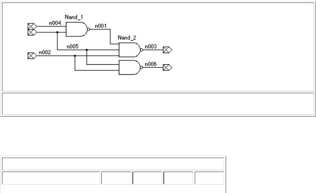
module primitive;
nand (strong0, strong1) #2.2 Nand_1(n001, n004, n005), Nand_2(n003, n001, n005, n002);
nand (n006, n005, n002); endmodule
This module models three NAND gates (Figure 11.2). The first gate (line 3) is a two-input gate named Nand_1 ; the second gate (line 4) is a three-input gate named Nand_2 ; the third gate (line 5) is unnamed. The first two gates have strong drive strengths [Verilog LRM3.4] (these are the defaults anyway) and 2.2 ns delay; the third gate takes the default values for drive strength (strong) and delay (zero). The first port of a primitive gate is always the output port. The remaining ports for a primitive gate (any number of them) are the input ports.
Table 11.5 shows the definition of the and gate primitive (I use lowercase 'and' as the name of the Verilog primitive, rather than 'AND' , since Verilog is case-sensitive). Notice that if one input to the primitive 'and' gate is zero, the output is zero, no matter what the other input is.
11.9.2 User-Defined Primitives
We can define primitive gates (a user-defined primitive or UDP) using a truth-table specification [Verilog LRM8]. The first port of a UDP must be an output port, and this must be the only o utput port (we may not use vector or inout ports):
primitive Adder(Sum, InA, InB); output Sum; input Ina, InB; table
// inputs : output 00 : 0; 01 : 1; 10 : 1; 11 : 0;
endtable endprimitive
We may only specify the values '0' , '1' , and 'x' as inputs in a UDP truth table. Any 'z' input is treated as an 'x' . If there is no entry in a UDP truth table that exactly matches a set of inputs, the output is 'x' (unknown).
We can construct a UDP model for sequential logic by including a state in the UDP truth-table definition. The state goes between an input and an output in the table and the output then represents the next state. The following sequential UDP model also illustrates the use of shorthand notation in a UDP truth table:
primitive DLatch(Q, Clock, Data); output Q; reg Q; input Clock, Data; table
//inputs : present state : output (next state)
1 0 : ? : 0; // ? represents 0,1, or x (input or present state). 1 1 : b : 1; // b represents 0 or 1 (input or present state).
1 1 : x : 1; // Could have combined this with previous line. 0 ? : ? : -; // - represents no change in an output. endtable
endprimitive
Be careful not to confuse the '?' in a UDP table (shorthand for '0' , '1' , or 'x' ) with the '?' in a constant that represents an extension to 'z' (Section 11.2.4) or the '?' in a case statement that represents don't care values (Section 11.8.1).
For sequential UDP models that need to detect edge transitions on inputs, there is another special truth-table notation (ab) that represents a change in logic value from a to b . For example, (01) represents a rising edge. There are also shorthand notations for various edges:
● * is (??)

●r is (01)
●f is (10)
●p is (01), (0x), or (x1)
●n is (10), (1x), or (x0)
primitive DFlipFlop(Q, Clock, Data); |
|
|
||||
output |
Q; reg Q; |
input Clock, Data; |
|
|
||
table |
|
|
|
|
|
|
//inputs |
: present state : output (next state) |
|||||
r |
0 |
: |
? : 0 ; |
// rising edge, next |
state |
= output = 0 |
r |
1 |
: |
? : 1 ; |
// rising edge, next |
state |
= output = 1 |
(0x) |
0 |
: |
0 : 0 ; |
// rising edge, next |
state |
= output = 0 |
(0x) |
1 |
: |
1 : 1 ; |
// rising edge, next |
state |
= output = 1 |
(?0) ? |
: |
? : - ; |
// falling edge, no change |
in output |
||
? (??) |
: |
? : - ; |
// no clock edge, no |
change in output |
||
endtable endprimitive
11.10 Modeling Delay
Verilog has a set of built-in methods to define delays. This is very important in ASIC physical design. Before we start layout, we can use ASIC cell library models written in Verilog that include logic delays as a function of fanout and estimated wiring loads. After we have completed layout, we can extract the wiring capacitance, allowing us to calculate the exact delay values. Using the techniques described in this section, we can then back-annotate our Verilog netlist with postlayout delays and complete a postlayout simulation.
We can complete this back-annotation process in a standard fashion since delay specification is part of the Verilog language. This makes working with an ASIC cell library and the ASIC foundry that will fabricate our ASIC much easier. Typically an ASIC library company might sell us a cell library complete with Verilog models that include all the minimum, typical, and maximum delays as well as the different values for rising and falling transitions. The ASIC foundry will provide us with a delay calculator that calculates the net delays (this is usually proprietary technology) from the layout. These delays are held in a separate file (the Standard Delay Format, SDF, is widely used) and then mapped to parameters in the Verilog models. If we complete back-annotation and a postlayout simulation using an approved cell library, the ASIC foundry will "sign off" on our design. This is basically a guarantee that our chip will work according to the simulation. This ability to design sign-off quality ASIC cell libraries is very important in the ASIC design process.
11.10.1 Net and Gate Delay
We saw how to specify a delay control for any statement in Section 11.6. In fact, Verilog allows us to specify minimum, typical, and maximum values for the delay as follows [Verilog LRM7.15]:
#(1.1:1.3:1.7) assign delay_a = a; // min:typ:max
We can also specify the delay properties of a wire in a similar fashion:
wire #(1.1:1.3:1.7) a_delay; // min:typ:max
We can specify delay in a wire declaration together with a continuous assignment as in the following example:
wire #(1.1:1.3:1.7) a_delay = a; // min:typ:max
but in this case the delay is associated with the driver and not with the wire .
In Section 11.9.1 we explained that we can specify a delay for a logic primitive. We can also specify minimum, typical, and maximum delays as well as separate delays for rising and falling transitions for primitives as follows [Verilog LRM4.3]:
nand #3.0 nd01(c, a, b);
nand #(2.6:3.0:3.4) nd02(d, a, b); // min:typ:max nand #(2.8:3.2:3.4, 2.6:2.8:2.9) nd03(e, a, b);

state-dependent path delay. Here is an example:
`timescale 1 ns / 100 fs
module M_Spec; reg A1, A2, B; M M1 (Z, A1, A2, B);
initial begin A1=0;A2=1;B=1;#5;B=0;#5;A1=1;A2=0;B=1;#5;B=0; end initial
$monitor("T=%4g",$realtime," A1=",A1," A2=",A2," B=",B," Z=",Z); endmodule
`timescale 100 ps / 10 fs
module M(Z, |
A1, A2, |
B); input A1, A2, B; output Z; |
|||
or (Z1, |
A1, |
A2); nand (Z, Z1, B); // OAI21 |
|||
/*A1 |
A2 |
B Z |
Delay=10*100 ps unless indicated in the table below. |
||
0 |
0 |
0 |
1 |
|
|
0 |
0 |
1 |
1 |
|
|
0 |
1 |
0 |
1 |
B:0->1 |
Z:1->0 delay=t2 |
0 |
1 |
1 |
0 |
B:1->0 |
Z:0->1 delay=t1 |
1 |
0 |
0 |
1 |
B:0->1 |
Z:1->0 delay=t4 |
1 |
0 |
1 |
0 |
B:1->0 |
Z:0->1 delay=t3 |
1 |
1 |
0 |
1 |
|
|
1 |
1 |
1 |
0 |
*/ |
|
specify specparam t1 |
= 11, t2 = 12; specparam t3 = 13, t4 = 14; |
||||
|
(A1 => Z) |
= 10; (A2 => Z) = 10; |
|||
|
if (~A1) (B => |
Z) = (t1, t2); if (A1) (B => Z) = (t3, t4); |
|||
endspecify |
|
|
|
||
endmodule |
|
|
|
||
T= |
0 |
A1=0 |
A2=1 |
B=1 |
Z=x |
T= |
1 |
A1=0 |
A2=1 |
B=1 |
Z=0 |
T= |
5 |
A1=0 |
A2=1 |
B=0 |
Z=0 |
T= 6.1 A1=0 |
A2=1 |
B=0 |
Z=1 |
||
T= |
10 |
A1=1 |
A2=0 |
B=1 |
Z=1 |
T= |
11 |
A1=1 |
A2=0 |
B=1 |
Z=0 |
T= |
15 |
A1=1 |
A2=0 |
B=0 |
Z=0 |
T=16.3 A1=1 |
A2=0 |
B=0 |
Z=1 |
||