


4.2 Static RAM
An example of static RAM ( SRAM ) programming technology is shown in Figure 4.5 . This Xilinx SRAM configuration cell is constructed from two cross-coupled inverters and uses a standard CMOS process. The configuration cell drives the gates of other transistors on the chip either turning pass transistors or transmission gates on to make a connection or off to break a connection.
FIGURE 4.5 The Xilinx SRAM (static RAM) configuration cell. The outputs of the cross-coupled inverter (configuration control) are connected to the gates of pass transistors or transmission gates. The cell is programmed using the WRITE and DATA lines.
The advantages of SRAM programming technology are that designers can reuse chips during prototyping and a system can be manufactured using ISP. This programming technology is also useful for upgrades a customer can be sent a new configuration file to reprogram a chip, not a new chip. Designers can also update or change a system on the fly in reconfigurable hardware .
The disadvantage of using SRAM programming technology is that you need to keep power supplied to the programmable ASIC (at a low level) for the volatile SRAM to retain the connection information. Alternatively you can load the configuration data from a permanently programmed memory (typically a programmable read-only memory or PROM ) every time you turn the system on. The total size of an SRAM configuration cell plus the transistor switch that the SRAM cell drives is also larger than the programming devices used in the antifuse technologies.
4.3 EPROM and EEPROM
Technology
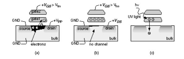
Altera MAX 5000 EPLDs and Xilinx EPLDs both use UV-erasable electrically programmable read-only memory ( EPROM ) cells as their programming technology. Altera's EPROM cell is shown in Figure 4.6 . The EPROM cell is almost as small as an antifuse. An EPROM transistor looks like a normal MOS transistor except it has a second, floating, gate (gate1 in Figure 4.6 ). Applying a programming voltage V PP (usually greater than 12 V) to the drain of the n- channel EPROM transistor programs the EPROM cell. A high electric field causes electrons flowing toward the drain to move so fast they jump across the insulating gate oxide where they are trapped on the bottom, floating, gate. We say these energetic electrons are hot and the effect is known as hot-electron injection or avalanche injection . EPROM technology is sometimes called floating-gate avalanche MOS ( FAMOS ).
FIGURE 4.6 An EPROM transistor. (a) With a high (> 12 V) programming voltage, V PP , applied to the drain, electrons gain enough energy to jump onto the floating gate (gate1). (b) Electrons stuck on gate1 raise the threshold voltage so that the transistor is always off for normal operating voltages. (c) Ultraviolet light provides enough energy for the electrons stuck on gate1 to jump back to the bulk, allowing the transistor to operate normally.
Electrons trapped on the floating gate raise the threshold voltage of the n- channel EPROM transistor ( Figure 4.6 b). Once programmed, an n- channel EPROM device remains off even with VDD applied to the top gate. An unprogrammed n- channel device will turn on as normal with a top-gate voltage of VDD . The programming voltage is applied either from a special programming

box or by using on-chip charge pumps. Exposure to an ultraviolet (UV) lamp will erase the EPROM cell ( Figure 4.6 c). An absorbed light quantum gives an electron enough energy to jump from the floating gate. To erase a part we place it under a UV lamp (Xilinx specifies one hour within 1 inch of a 12,000 m Wcm 2 source for its EPLDs). The manufacturer provides a software program that checks to see if a part is erased. You can buy an EPLD part in a windowed package for development, erase it, and use it again, or buy it in a nonwindowed package and program (or burn) the part once only for production. The packages get hot while they are being erased, so that windowed option is available with only ceramic packages, which are more expensive than plastic packages.
Programming an EEPROM transistor is similar to programming an UV-erasable EPROM transistor, but the erase mechanism is different. In an EEPROM transistor an electric field is also used to remove electrons from the floating gate of a programmed transistor. This is faster than using a UV lamp and the chip does not have to be removed from the system. If the part contains circuits to generate both program and erase voltages, it may use ISP.
4.4 Practical Issues
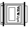
System companies often select an ASIC technology first, which narrows the choice of software design tools. The software then influences the choice of computer. Most computer-aided engineering ( CAE ) software for FPGA design uses some type of security. For workstations this usually means floating licenses (any of n users on a network can use the tools) or node-locked licenses (only n particular computers can use the tools) using the hostid (or host I.D., a serial number unique to each computer) in the boot EPROM (a chip containing start-up instructions). For PCs this is a hardware key, similar to the Viewlogic key illustrated in Figure 4.7 . Some keys use the serial port (requiring extra cables and adapters); most now use the parallel port. There are often conflicts between keys and other hardware/software. For example, for a while some security keys did not work with the serial-port driver on Intel motherboards users had to buy another serial-port I/O card.
FIGURE 4.7 CAE companies use hardware security keys that fit at the back of a PC (this one is shown at about one-half the real size). Each piece of software requires a separate key, so that a typical design system may have a half dozen or more keys daisy-chained on one socket. This presents both mechanical and software conflict problems. Software will not run without a key, so it is easily possible to have $60,000 worth of keys attached to a single PC.
Most FPGA vendors offer software on multiple platforms. The performance difference between workstations and PCs is becoming blurred, but the time taken for the place-and-route step for Actel and Xilinx designs seems to remain constant typically taking tens of minutes to over an hour for a large designbounded by designers tolerances.
A great deal of time during FPGA design is spent in schematic entry, editing files, and documentation. This often requires moving between programs and this is difficult on IBM-compatible PC platforms. Currently most large CAD and CAE programs completely take over the PC; for example you cannot always run third-party design entry and the FPGA vendor design systems simultaneously.
There are many other factors to be considered in choosing hardware:
●Software packages are normally less expensive on a PC.
●Peripherals are less expensive and easier to configure on a PC.
●Maintenance contracts are usually necessary and expensive for workstations.
●There is a much larger network of users to provide support for PC users.
●It is easier to upgrade a PC than a workstation.
4.4.1 FPGAs in Use
I once placed an order for a small number of FPGAs for prototyping and received a sales receipt with a scheduled shipping date three months away. Apparently, two customers had recently disrupted the vendor s product planning by placing large orders. Companies buying parts from suppliers often keep an inventory to cover emergencies such as a defective lot or manufacturing problems. For example, assume that a company keeps two months of inventory to ensure that it has parts in case of unforeseen problems. This risk inventory or safety supply, at a sales volume of 2000 parts per month, is 4000 parts, which, at an ASIC price of $5 per part, costs the company $20,000. FPGAs are normally sold through distributors, and, instead of keeping a risk inventory, a company can order parts as it needs them using a just-in-time ( JIT ) inventory system. This means that the distributors rather than the customer carry inventory (though the distributors wish to minimize inventory as well). The downside is that other customers may change their demands, causing unpredictable supply difficulties.
There are no standards for FPGAs equivalent to those in the TTL and PLD worlds; there are no standard pin assignments for VDD or GND, and each FPGA vendor uses different power and signal I/O pin arrangements. Most FPGA packages are intended for surface-mount printed-circuit boards ( PCBs ). However, surface mounting requires more expensive PCB test equipment and vapor soldering rather than bed-of-nails testers and surface-wave soldering. An alternative is to use socketed parts. Several FPGA vendors publish socket-reliability tests in their data books.
Using sockets raises its own set of problems. First, it is difficult to find wire-wrap sockets for surface-mount parts. Second, sockets may change the pin configuration. For example, when you use an FPGA in a PLCC package and plug it into a socket that has a PGA footprint, the resulting arrangement of pins is different from the same FPGA in a PGA package. This means you cannot use the same board layout for a prototype PCB (which uses the socketed PLCC part) as for the production PCB (which uses the PGA part). The same problem occurs when you use through-hole mounted parts for prototyping and surface-mount parts for production. To deal with this you can add a small piece to your prototype board that you use as a converter. This can be sawn off on the production boards saving a board iteration.
Pin assignment can also cause a problem if you plan to convert an FPGA design to an MGA or CBIC. In most cases it is desirable to keep the same pin assignment as the FPGA (this is known as pin locking or I/O locking ), so that the
same PCB can be used in production for both types of devices. There are often restrictions for custom gate arrays on the number and location of power pads and package pins. Systems designers must consider these problems before designing the FPGA and PCB.