

11.5 Procedures and Assignments
A Verilog procedure [Verilog LRM 9.9] is an always or initial statement, a task , or a function . The statements within a sequential block (statements that appear between a begin and an end ) that is part of a procedure execute sequentially in the order in which they appear, but the procedure executes concurrently with other procedures. This is a fundamental difference from computer programming languages. Think of each procedure as a microprocessor running on its own and at the same time as all the other microprocessors (procedures). Before I discuss procedures in more detail, I shall discuss the two different types of assignment statements:
●continuous assignments that appear outside procedures
●procedural assignments that appear inside procedures
To illustrate the difference between these two types of assignments, consider again the example used in Section 11.4:
module holiday_1(sat, sun, weekend); input sat, sun; output weekend;
assign weekend = sat | sun; // Assignment outside a procedure. endmodule
We can change weekend to a reg instead of a wire , but then we must declare weekend and use a procedural assignment (inside a procedure--an always statement, for example) instead of a continuous assignment. We also need to add some delay (one time tick in the example that follows); otherwise the computer will never be able to get out of the always procedure to execute any other procedures:
module holiday_2(sat, sun, weekend);
input sat, sun; output weekend; reg weekend;
always #1 weekend = sat | sun; // Assignment inside a procedure. endmodule
We shall cover the continuous assignment statement in the next section, which is followed by an explanation of sequential blocks and procedural assignment statements. Here is some skeleton code that illustrates where we may use these assignment statements:
module assignments
//... Continuous assignments go here. always // beginning of a procedure
begin // beginning of sequential block //... Procedural assignments go here. end
endmodule
Table 11.4 at the end of Section 11.6 summarizes assignment statements, including two more forms of assignment--you may want to look at this table now.
11.5.1 Continuous Assignment Statement
A continuous assignment statement [Verilog LRM 6.1] assigns a value to a wire in a similar way that a real logic gate drives a real wire,
module assignment_1();
wire pwr_good, pwr_on, pwr_stable; reg Ok, Fire; assign pwr_stable = Ok & (!Fire);
assign pwr_on = 1;
assign pwr_good = pwr_on & pwr_stable;
initial begin Ok = 0; Fire = 0; #1 Ok = 1; #5 Fire = 1; end initial begin $monitor("TIME=%0d",$time," ON=",pwr_on, " STABLE=",
pwr_stable," OK=",Ok," FIRE=",Fire," GOOD=",pwr_good); #10 $finish; end
endmodule
TIME=0 ON=1 STABLE=0 OK=0 FIRE=0 GOOD=0
TIME=1 ON=1 STABLE=1 OK=1 FIRE=0 GOOD=1
TIME=6 ON=1 STABLE=0 OK=1 FIRE=1 GOOD=0
The assignment statement in this next example models a three-state bus:
module assignment_2; reg Enable; wire [31:0] Data;
/* The following single statement is equivalent to a declaration and continuous assignment. */
wire [31:0] DataBus = Enable ? Data : 32'bz; assign Data = 32'b10101101101011101111000010100001;
initial begin
$monitor("Enable=%b DataBus=%b ", Enable, DataBus); Enable = 0; #1; Enable = 1; #1; end
endmodule
Enable = 0 DataBus =zzzzzzzzzzzzzzzzzzzzzzzzzzzzzzzz Enable = 1 DataBus =10101101101011101111000010100001
11.5.2 Sequential Block
A sequential block [Verilog LRM 9.8] is a group of statements between a begin and an end. We may declare new variables within a sequential block, but then we must name the block. A sequential block is considered a statement, so that we may nest sequential blocks.
A sequential block may appear in an always statement [Verilog LRM9.9.2], in which case the block executes repeatedly. In contrast, an initial statement [Verilog LRM9.9.1] executes only once, so a sequential block within an initial statement only executes once--at the beginning of a simulation. It does not matter where the initial statement appears--it still executes first. Here is an example:
module always_1; reg Y, Clk;
always // Statements in an always statement execute repeatedly: begin: my_block // Start of sequential block.
@(posedge |
Clk) |
#5 Y = 1; // At +ve edge set Y=1, |
|
@(posedge |
Clk) #5 Y = 0; // at the NEXT +ve edge set Y=0. |
||
end // End of sequential block. |
|||
always #10 Clk = ~ Clk; // We need a clock. |
|||
initial Y = 0; // These initial statements execute |
|||
initial Clk |
= 0; |
// only once, but first. |
|
initial $monitor("T=%2g",$time," Clk=",Clk," Y=",Y); |
|||
initial #70 $finish; |
|||
endmodule |
|
|
|
T= 0 |
Clk=0 |
Y=0 |
|
T=10 |
Clk=1 |
Y=0 |
|
T=15 |
Clk=1 |
Y=1 |
|
T=20 |
Clk=0 |
Y=1 |
|
T=30 |
Clk=1 |
Y=1 |
|
T=35 |
Clk=1 |
Y=0 |
|
T=40 |
Clk=0 |
Y=0 |
|
T=50 |
Clk=1 |
Y=0 |
|
T=55 |
Clk=1 |
Y=1 |
|
T=60 |
Clk=0 |
Y=1 |
|
11.5.3 Procedural Assignments
A procedural assignment [Verilog LRM 9.2] is similar to an assignment statement in a computer programming language such as C. In Verilog the value of an expression on the RHS of an assignment within a procedure (a procedural assignment) updates a reg (or memory element) on the LHS. In the absence of any timing controls (see Section 11.6), the reg is updated immediately when the statement executes. The reg holds its value until changed by another procedural assignment. Here is the BNF definition:

blocking_assignment ::= reg-lvalue = [delay_or_event_control] expression
(Notice this BNF definition is for a blocking assignment--a type of procedural assignment--see Section 11.6.4.) Here is an example of a procedural assignment (notice that a wire can only appear on the RHS of a procedural assignment):
module procedural_assign; reg Y, A; always @(A)
Y = A; // Procedural assignment.
initial begin A=0; #5; A=1; #5; A=0; #5; $finish; end initial $monitor("T=%2g",$time,,"A=",A,,,"Y=",Y); endmodule
T= 0 A=0 Y=0
T= 5 A=1 Y=1
T=10 A=0 Y=0
11.6 Timing Controls and Delay
The statements within a sequential block are executed in order, but, in the absence of any delay, they all execute at the same simulation time--the current time step. In reality there are delays that are modeled using a timing control.
11.6.1 Timing Control
A timing control is either a delay control or an event control [Verilog LRM 9.7]. A delay control delays an assignment by a specified amount of time. A timescale compiler directive is used to specify the units of time followed by the precision used to calculate time expressions,
`timescale 1ns/10ps // Units of time are ns. Round times to 10 ps.
Time units may only be s , ns , ps , or fs and the multiplier must be 1, 10, or 100. We can delay an assignment in two different ways:
●Sample the RHS immediately and then delay the assignment to the LHS.
●Wait for a specified time and then assign the value of the LHS to the RHS.
Here is an example of the first alternative (an intra-assignment delay):
x = #1 y; // intra-assignment delay
The second alternative is delayed assignment:
#1 x = y; // delayed assignment
These two alternatives are not the same. The intra-assignment delay is equivalent to the following code:
begin // Equivalent to intra-assignment delay. hold = y; // Sample and hold y immediately. #1; // Delay.
x = hold; // Assignment to x. Overall same as x = #1 y. end
In contrast, the delayed assignment is equivalent to a delay followed by an assignment as follows:
begin // Equivalent to delayed assignment. #1; // Delay.
x = y; // Assign y to x. Overall same as #1 x = y. end
The other type of timing control, an event control, delays an assignment until a specified event occurs. Here is the formal definition:
event_control ::= @ event_identifier | @ (event_expression) event_expression ::= expression | event_identifier
| posedge expression | negedge expression
| event_expression or event_expression
(Notice there are two different uses of 'or' in this simplified BNF definition--the last one, in bold, is part of the Verilog language, a keyword.) A positive edge (denoted by the keyword posedge ) is a transition from '0' to '1' or 'x' , or a transition from 'x' to '1 '. A negative edge ( negedge ) is a transition from '1' to '0' or 'x' , or a transition from 'x' to '0'. Transitions to or from 'z' do not count. Here are examples of event controls:
module delay_controls; reg X, Y, Clk, Dummy;
always #1 Dummy=!Dummy; // Dummy clock, just for graphics.
//Examples of delay controls: always begin #25 X=1;#10 X=0;#5; end
//An event control:
always @(posedge Clk) Y=X; // Wait for +ve clock edge. always #10 Clk = !Clk; // The real clock.
initial begin |
Clk = |
0; |
$display("T |
Clk |
X Y"); |
$monitor("%2g",$time,,,Clk,,,,X,,Y); $dumpvars;#100 $finish; end
endmodule
T |
Clk |
X Y |
|
0 |
0 |
x x |
|
10 |
1 |
x x |
|
20 |
0 |
x x |
|
25 |
0 |
1 |
x |
30 |
1 |
1 |
1 |
35 |
1 |
0 |
1 |
40 |
0 |
0 |
1 |
50 |
1 |
0 |
0 |
60 |
0 |
0 |
0 |
65 |
0 |
1 |
0 |
70 |
1 |
1 |
1 |
75 |
1 |
0 |
1 |
80 |
0 |
0 |
1 |
90 |
1 |
0 |
0 |
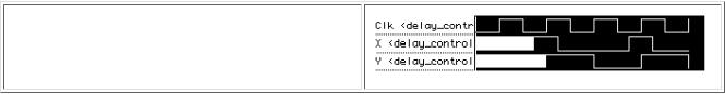
The dummy clock in delay_controls helps in the graphical waveform display of the results (it provides a one-time-tick timing grid when we zoom in, for example). Figure 11.1 shows the graphical output from the Waves viewer in VeriWell (white is used to represent the initial unknown values). The assignment statements to 'X' in the always statement repeat (every 25 + 10 + 5 = 40 time ticks).
Events can be declared (as named events), triggered, and detected as follows:
module show_event; reg clock;
event event_1, event_2; // Declare two named events. always @(posedge clock) -> event_1; // Trigger event_1. always @ event_1
begin $display("Strike 1!!"); -> event_2; end // Trigger event_2. always @ event_2 begin $display("Strike 2!!");
$finish; end // Stop on detection of event_2. always #10 clock = ~ clock; // We need a clock. initial clock = 0;
endmodule
Strike 1!! Strike 2!!
11.6.2 Data Slip
Consider this model for a shift register and the simulation output that follows:
module data_slip_1 (); reg Clk, D, Q1, Q2;
/************* bad sequential logic below ***************/
always @(posedge Clk) Q1 = D;
always @(posedge Clk) Q2 = Q1; // Data slips here! /************* bad sequential logic above ***************/
initial |
begin Clk = 0; D = 1; end always #50 Clk = ~Clk; |
||||
initial |
begin $display("t |
Clk D Q1 Q2"); |
|||
$monitor("%3g",$time,,Clk,,,,D,,Q1,,,Q2); end |
|||||
initial |
#400 |
$finish; // Run for 8 cycles. |
|||
initial |
$dumpvars; |
|
|||
endmodule |
|
|
|
||
t |
Clk |
D |
Q1 |
Q2 |
|
0 |
0 |
1 |
x |
x |
|
50 |
1 |
1 |
1 |
1 |
|
100 |
0 |
1 |
1 |
1 |
|
150 |
1 |
1 |
1 |
1 |
|
200 |
0 |
1 |
1 |
1 |
|
250 |
1 |
1 |
1 |
1 |
300 |
0 |
1 |
1 |
1 |
350 |
1 |
1 |
1 |
1 |
The first clock edge at t = 50 causes Q1 to be updated to the value of D at the clock edge (a '1' ), and at the same time Q2 is updated to this new value of Q1 . The data, D , has passed through both always statements. We call this problem data slip.
If we include delays in the always statements (labeled 3 and 4) in the preceding example, like this--
always @(posedge Clk) Q1 = #1 D; // The delays in the assignments always @(posedge Clk) Q2 = #1 Q1; // fix the data slip.
--we obtain the correct output:
t |
Clk |
D Q1 |
Q2 |
|
0 |
0 |
1 |
x |
x |
50 |
1 |
1 |
x |
x |
51 |
1 |
1 |
1 |
x |
100 |
0 |
1 |
1 |
x |
150 |
1 |
1 |
1 |
x |
151 |
1 |
1 |
1 |
1 |
200 |
0 |
1 |
1 |
1 |
250 |
1 |
1 |
1 |
1 |
300 |
0 |
1 |
1 |
1 |
350 |
1 |
1 |
1 |
1 |
11.6.3 Wait Statement
The wait statement [Verilog LRM9.7.5] suspends a procedure until a condition becomes true. There must be another concurrent procedure that alters the condition (in this case the variable Done --in general the condition is an expression) in the following wait statement; otherwise we are placed on "infinite hold":
wait (Done) $stop; // Wait until Done = 1 then stop.
Notice that the Verilog wait statement does not look for an event or a change in the condition; instead it is level-sensitive--it only cares that the condition is true.
module test_dff_wait;
reg D, Clock, Reset; dff_wait u1(D, Q, Clock, Reset);
initial begin D=1; Clock=0;Reset=1'b1; #15 Reset=1'b0; #20 D=0; end always #10 Clock = !Clock;
initial begin $display("T Clk D Q Reset"); $monitor("%2g",$time,,Clock,,,,D,,Q,,Reset); #50 $finish; end
endmodule
module dff_wait(D, Q, Clock, Reset);
output Q; input D, Clock, Reset; reg Q; wire D; always @(posedge Clock) if (Reset !== 1) Q = D;
always begin wait (Reset == 1) Q = 0; wait (Reset !== 1); end
endmodule |
|
|
||
T |
Clk D Q |
Reset |
||
0 |
0 |
1 |
0 |
1 |
10 |
1 |
1 |
0 |
1 |
15 |
1 |
1 |
0 |
0 |
20 |
0 |
1 |
0 |
0 |
30 |
1 |
1 |
1 |
0 |
35 |
1 |
0 |
1 |
0 |
40 |
0 |
0 |
1 |
0 |
We must include wait statements in module dff_wait above to wait for both Reset==1 and Reset==0 . If we were to omit the wait statement for Reset==0 , as in the following code:
module dff_wait(D,Q,Clock,Reset);
output Q; input D,Clock,Reset; reg Q; wire D; always @(posedge Clock) if (Reset !== 1) Q = D;
// We need another wait statement here or we shall spin forever. always begin wait (Reset == 1) Q = 0; end
endmodule
the simulator would cycle endlessly, and we would need to press the 'Stop' button or 'CTRL-C' to halt the simulator. Here is the console window in VeriWell:
C1> . |
|
T Clk D Q Reset |
<- at this point nothing happens, so press CTRL-C |
Interrupt at time 0 |
|
C1> |
|
11.6.4 Blocking and Nonblocking Assignments
If a procedural assignment in a sequential block contains a timing control, then the execution of the following statement is delayed or blocked. For this reason a procedural assignment statement is also known as a blocking procedural assignment statement [Verilog LRM 9.2]. We covered this type of statement in Section 11.5.3. The nonblocking procedural assignment statement allows execution in a sequential block to continue and registers are all updated together at the end of the current time step. Both types of procedural assignment may contain timing controls. Here is an artificially complicated example that illustrates the different types of assignment:
module delay;
reg a,b,c,d,e,f,g,bds,bsd;
initial begin |
|
|
a = 1; b = 0; // |
No delay control. |
|
#1 b = 1; |
// |
Delayed assignment. |
c = #1 1; |
// |
Intra-assignment delay. |
#1; |
// |
Delay control. |
d = 1; |
// |
|
e <= #1 1; |
// |
Intra-assignment delay, nonblocking assignment |
#1 f <= 1; |
// |
Delayed nonblocking assignment. |
g <= 1; |
// |
Nonblocking assignment. |
end |
|
|
initial begin #1 bds = b; end // Delay then sample (ds). initial begin bsd = #1 b; end // Sample then delay (sd). initial begin $display("t a b c d e f g bds bsd"); $monitor("%g",$time,,a,,b,,c,,d,,e,,f,,g,,bds,,,,bsd); end endmodule
t a |
b c d e f |
g bds |
bsd |
||||||
0 |
1 |
0 |
x x x x |
x x |
x |
||||
1 |
1 |
1 |
x x x x |
x 1 |
0 |
||||
2 |
1 |
1 |
1 |
x x x |
x 1 |
0 |
|||
3 |
1 |
1 |
1 |
1 |
x x |
x 1 |
0 |
||
4 |
1 |
1 |
1 |
1 |
1 |
1 |
1 |
1 |
0 |
Many synthesis tools will not allow us to use blocking and nonblocking procedural assignments to the same reg within the same sequential block.
11.6.5 Procedural Continuous Assignment
A procedural continuous assignment statement [Verilog LRM 9.3] (sometimes called a quasicontinuous assignment statement) is a special form of the assign statement that we use within a sequential block. For example, the following flip-flop model assigns to q depending on the clear, clr_, and preset, pre_, inputs (in general it is considered very bad form to use a trailing underscore to signify active-low signals as I have done to save space; you might use " _n " instead).
module dff_procedural_assign;
reg d,clr_,pre_,clk; wire q; dff_clr_pre dff_1(q,d,clr_,pre_,clk); always #10 clk = ~clk;
initial begin clk = 0; clr_ = 1; pre_ = 1; d = 1;
#20; d = 0; #20; pre_ = 0; #20; pre_ = 1; #20; clr_ = 0; #20; clr_ = 1; #20; d = 1; #20; $finish; end
initial begin
$display("T CLK PRE_ CLR_ D Q"); $monitor("%3g",$time,,,clk,,,,pre_,,,,clr_,,,,d,,q); end
endmodule
module dff_clr_pre(q,d,clear_,preset_,clock); output q; input d,clear_,preset_,clock; reg q; always @(clear_ or preset_)
if (!clear_) assign q = 0; // active-low clear
else if(!preset_) assign q = 1; // active-low preset
else |
deassign q; |
|
|||
always |
@(posedge |
clock) q = d; |
|||
endmodule |
|
|
|
||
T |
CLK |
PRE_ CLR_ |
D Q |
||
0 |
0 |
1 |
1 |
1 |
x |
10 |
1 |
1 |
1 |
1 |
1 |
20 |
0 |
1 |
1 |
0 |
1 |
30 |
1 |
1 |
1 |
0 |
0 |
40 |
0 |
0 |
1 |
0 |
1 |
50 |
1 |
0 |
1 |
0 |
1 |
60 |
0 |
1 |
1 |
0 |
1 |
70 |
1 |
1 |
1 |
0 |
0 |
80 |
0 |
1 |
0 |
0 |
0 |
90 |
1 |
1 |
0 |
0 |
0 |
100 |
0 |
1 |
1 |
0 |
0 |
110 |
1 |
1 |
1 |
0 |
0 |
120 |
0 |
1 |
1 |
1 |
0 |
130 |
1 |
1 |
1 |
1 |
1 |
We have now seen all of the different forms of Verilog assignment statements. The following skeleton code shows where each type of statement belongs:
module all_assignments
//... continuous assignments. always // beginning of procedure
begin // beginning of sequential block //... blocking procedural assignments. //... nonblocking procedural assignments. //... procedural continuous assignments. end
endmodule
Table 11.4 summarizes the different types of assignments.