


11 Glossary
11.1Catalog of small antennas
Small antennas here are treated in a wider sense than generally used (which concerns only ESA), because of its significance in the antenna and communication community. However, in consideration of the latest trends and requirements for small antennas, the variety of wireless systems including wireless broadband systems and short range radio systems, demands for a variety of antennas having physically constrained dimensions as well as electrically small dimensions and enhanced functions have become urgent. Thus, describing only ESA in the modern book is considered insufficient, whereas introduction of other types of antennas such as PCSA, FSA, and PSA should be preferred, as they have been widely employed in recently deployed wireless systems. The book describes principles of small sizing for antennas, design techniques, including miniaturization, and many antenna examples. The latest design technologies include application of metamaterials, EBG (Electromagnetic Band Gap), HIS (High Impedance Surface), DGS (Defect Ground Surface), and so forth.
This chapter contains a catalog of antennas listed in earlier book chapters, providing the original figure which can be referred by numbers used in the text and figures not appeared in the text with number with A as Fig. Ax. (x: a serial number in the catalog.). The main feature of the chapter is to provides readers with some useful information for designing small antennas and assistance in selecting suitable antennas for systems.
The list gives brief view, main features and some examples of applications. In addition, for the reader’s convenience, references and locations, indicating the section in the text where readers can refer, are provided.
11.2List of small antennas

|
|
|
|
|
|
|
|
|
|
|
|
|
|
References |
|
|
|
|
|
|
|
|
|
|
|
|
|
|
and location |
Brief view |
Antenna type |
|
|
|
Main features |
Applications |
in the text |
|||||||
|
|
|
|
|
|
|
|
|
|
|
|
|
||
|
Short dipole |
|
|
|
Low radiation resistance, high capacitive |
Small mobile terminals (Handset) |
[1–4] |
|||||||
|
2a |
|
|
λ |
|
|
|
reactance, narrowband |
RFID |
Chapter 3 |
||||
|
≤λ2π |
|
|
|
Low radiation efficiency (with high loss |
|
Figure 3.1 |
|||||||
|
d |
|
|
|
|
|
||||||||
|
|
|
|
|
|
|
|
|
|
|
matching circuit) small, thin, lightweight, |
|
|
|
|
|
|
|
|
|
|
|
|
|
|
|
low cost |
|
|
|
Monopole |
|
|
|
Low radiation resistance, high capacitive |
Small mobile terminals (Handset) |
[5, 6]* |
|||||||
|
(on the ground |
reactance, narrowband |
RFID |
*not |
||||||||||
|
plane) |
|
|
|
|
|
|
|
|
Low radiation efficiency (with high loss |
|
necessarily |
||
|
a ≤ |
λ |
|
|
|
matching circuit) small, thin, lightweight, |
|
ESA |
||||||
|
|
|
|
|
|
|
|
low cost |
|
|||||
|
4π |
|
|
|
|
|
||||||||
|
Inverted-L (ILA) |
Low-profile, thin, lightweight, low cost |
HF band communications |
[7, 8] |
||||||||||
|
(on the ground |
Low radiation resistance, high capacitive |
vehicles, ships |
Figure 1.6(c) |
||||||||||
|
plane) |
1 |
|
|
|
|
reactance, vertical polarization (with low |
|
|
|||||
|
|
|
|
|
|
|
|
h), horizontal polarization (possible with |
|
|
||||
|
L + h ≤ |
|
|
λ |
|
|
|
|||||||
|
4 |
higher h) |
|
|
||||||||||
|
Inverted-F (IFA) |
Low-profile, thin, lightweight, low cost |
VHF/UHF band communications |
[7, 9] |
||||||||||
|
(on the ground |
Easily matching to 50 (with adjustment of |
vehicles |
Figure 1.6(d) |
||||||||||
|
plane) |
|
|
|
|
|
4 |
|
h and d) |
Small mobile terminals (Handset) |
|
|||
|
d + λ ≤ |
|
|
|
|
|||||||||
|
L |
|
|
h |
1 |
λ |
|
|
|
|||||
|
|
|
|
|
|
|
||||||||
|
|
|
|
|
|
|
|
|
|
|
|
|
||
|
Small loop |
|
|
|
Low radiation resistance, high inductive |
Small portable equipment |
[10–12] |
|||||||
|
(circular) |
|
|
|
reactance small, thin, lightweight, compact |
NFC systems (including card type |
Figure 3.3 |
|||||||
|
ka 1 |
|
|
|
|
RFID) |
|
|||||||
|
(rectangular) |
|
|
|
Small, thin, lightweight, compact |
Small portable equipment |
[13, 14] |
|||||||
|
|
|
|
|
|
|
|
|
|
|
|
|
NFC systems (including card type |
Figure 3.5 |
|
|
|
|
|
|
|
|
|
|
|
|
|
RFID) |
|


|
|
|
|
References |
|
|
|
|
and location |
Brief view |
Antenna type |
Main features |
Applications |
in the text |
|
|
|
|
|
|
Dual-element MLA |
Dual-band operation |
Small mobile terminals |
[37] |
|
(on the ground |
|
|
Figure 7.9 |
|
plane) |
|
|
|
Normal mode helical |
Slow-wave structure, radiation normal to the |
Small mobile terminals |
[38–41] |
|||||||
antenna (NMHA) |
helix axis with the same pattern as a short |
(Handsets) |
Figure 6.15 |
|||||||
2a λ |
1 λ |
dipole of the same axial length, |
|
|
||||||
L |
= |
np < |
Self-resonance possible with increase in n, |
|
|
|||||
|
|
|
4 |
|
1 |
λ, Higher efficiency |
|
|
||
|
|
|
|
|
|
even though L |
|
|
|
|
|
|
|
|
|
|
4 |
|
|
||
|
|
|
|
|
|
than that of a dipole with the same length |
|
|
||
Dipole type |
|
|
|
|
|
|
|
[42, 43] |
||
|
|
|
|
|
|
|
|
|
|
Figure 7.57 |
Monopole type (on |
|
|
|
|
[44, 45] |
|||||
the ground plane) |
|
|
|
|
Figure 7.70 |
|||||


|
|
|
|
References |
|
|
|
|
and location |
Brief view |
Antenna type |
Main features |
Applications |
in the text |
|
|
|
|
|
|
Minkowsky type |
|
|
Figure 7.103 |
Sierpinsky type |
Multiband operation, number of multiple |
Multiband systems |
[67, 68] |
|
bands are adjusted by control of scale |
|
7.2.2 |
|
factor to generate Sierpinsky geometry |
|
7.2.2.1.3.3 |
|
|
|
Figure 7.106 |
Monopole type |
|
|
|
with: |
|
|
|
Hilbert curve |
|
|
Figure 7.103 |
Meander line, Fractal |
|
|
[69, 70] |
geometries, etc. |
|
|
7.2.2.1.3.2 |
|
|
|
Figure 7.103 |
PIFA with planar |
Dual-band operation by using two different |
Mobile phone, dual band |
[71] |
Peano elements |
Peano wire elements as horizontal element |
|
7.2.2.1.1.1 |
|
in PIFA structure |
|
Figure 7.97 |


|
|
|
|
References |
|
|
|
|
and location |
Brief view |
Antenna type |
Main features |
Applications |
in the text |
|
|
|
|
|
|
Top-loaded Antenna |
|
|
|
|
Circular disk |
Electrically small size (height), uniform |
|
[87, 88] |
|
|
current distribution on the monopole |
|
7.2.3.1.1 |
|
|
element |
|
Figure 7.168 |
|
Wire-grid disk dipole, |
Self-resonant, resonance frequency lowered |
|
[74] |
|
monopole |
by increasing disk diameter, increasing |
|
7.2.3.1.1 |
|
|
capacitance, a shunt stack point used for |
|
Figure 7.169 |
|
|
matching |
|
|
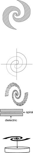
Spiral disk |
Self-resonance, resonance frequency lowered |
[75] |
|
by varying spiral wire length, increasing |
7.2.3.1.1 |
|
both capacitance and inductance |
Figure 7.169 |
Disk-loaded helix |
Self-resonance, resonance frequency lowered |
[74] |
|
by both top-loading and helical winding, |
7.2.3.1.1 |
|
increasing capacitance and inductance |
Figure 7.169 |


|
|
|
|
References |
|
|
|
|
and location |
Brief view |
Antenna type |
Main features |
Applications |
in the text |
|
|
|
|
|
|
Electrically small |
Almost isotropic radiation pattern, diameter |
|
[94] |
|
spherical wire |
about 20 cm, resonance at 327 MHz, Q |
|
7.2.2.2.3.3 |
|
dipole antenna |
about 12, close to the lower bound Qchu, |
|
Figure 7.152 |
|
|
efficiency 93% |
|
|
|
Spherical split ring |
Electrically small size (radius 21cm, |
|
[95] |
|
resonator (SSRR) |
resonance at 300 MHz), optimized with Q |
|
7.2.2.2.3.4 |
|
antenna |
≈ 3.5Qchu |
|
Figure 7.160 |
|
Electrically small |
Electrically small size (height λ/18, |
|
[96] |
|
complementary |
(height/diameter) = 1), 3:1 VSWR |
|
7.2.4.2.1 |
|
pairs of thick |
bandwidth, gain 5.75 dB, minimum |
|
Figure 7.194 |
|
monopole antennas |
efficiency 25% |
|
|
|
Combined electric |
Small size (25×20 cm), unidirectional |
|
[97] |
|
and magnetic type |
radiation over wide bandwidth, Combined |
|
7.2.4.2.2 |
|
planar antenna |
electrical radiator (two dipole arms) with |
|
Figure 7.196 |
|
|
magnetic radiator (a loop cut on the ground |
|
|
|
|
plane) |
|
|

|
|
|
|
References |
|
|
|
|
and location |
Brief view |
Antenna type |
Main features |
Applications |
in the text |
|
|
|
|
|
|
• MNG material |
|
|
Figure 7.212 |
|
constituted of |
|
|
|
|
single ring array |
|
|
|
|
• Elliptical patch |
|
|
Figure 7.214 |
|
antenna loaded |
|
|
|
|
with MNG material |
|
|
|
|
Epsilon-negative |
Miniaturized monopole antenna; example: |
|
[102] |
|
material (ENG) |
ENG half-sphere radius of λ/18 and the |
|
7.2.5.1.2 |
|
loaded antenna |
monopole length λ/50 at λ = 14.8 cm, |
|
Figure 7.218 |
|
Monopole loaded |
Q = 42 (about 1.5Qchu) |
|
|
|
with a half-sphere |
|
|
|
|
ENG material |
|
|
|
|
Loop antenna loaded |
Miniaturized loop antenna with ka = 0.11, |
|
[103] |
|
with an equivalent |
resonance at 300 MHz, narrow bandwidth |
|
7.2.5.1.1.3 |
|
MNG structure |
|
|
Figure 7.217 |
|
placed on a finite |
|
|
|
|
ground plane |
|
|
|
|
Rectangular loop |
MNG structure is synthesized by either 3D |
|
[103] |
|
antenna loaded |
extended capacitor-loaded loop (CLL) or |
|
7.2.5.1.1 |
|
with an equivalent |
2D planar CLL with inter-digital capacitor |
|
Figure 7.217 |
|
MNG structure |
or a lumped capacitor |
|
|
|
with inter-digital |
|
|
|
|
capacitor |
|
|
|


|
|
|
|
References |
|
|
|
|
and location |
Brief view |
Antenna type |
Main features |
Applications |
in the text |
|
|
|
|
|
|
Backfire-to-endfire |
Antenna constituted of a 1D CRLH |
|
[104] |
|
fan beam CRLH |
metamaterial structure incorporating |
|
7.2.5.2.1 |
|
Leaky Wave |
series-resonant tank with inter-digital |
|
Figure 7.227 |
|
antenna |
capacitor and shunt anti-resonant tank with |
|
|
|
|
stub inductor |
|
|
|
Conical beam antenna |
Opening angle of conical beam varies with |
|
[104] |
|
using 2D CRLH |
frequency, following the dispersion relation |
|
7.2.5.2.1 |
|
LW antenna |
(β/ω), leading to beam scanning |
|
Figure 7.227 |
|
3D CRLH (rotated |
|
|
[104] |
|
TL-matrix based) |
|
|
7.2.5.2.1 |
|
material |
|
|
Figure 7.227 |
|
CRLH ZOR mode |
With ZOR property, operating frequency not |
|
[104] |
|
microstrip |
depending on the size, but only on the |
|
7.2.5.2.2 |
|
resonator antennas |
lumped LC values, leading to create ESA. |
|
Figure 7.230 |
|
(three models for |
Increasing size increases gain with fixed |
|
|
|
different |
frequency, high efficiency and high |
|
|
|
frequencies) |
directivity |
|
|
|
A CRLH loop |
A rectilinear CRLH structure with compactly |
|
[104] |
|
resonant microstrip |
spaced stubs in a radial manner, shorted at |
|
Figure 7.231 |
|
antenna |
the center of the structure, Monopole-like |
|
|
|
|
radiation with ZOR mode |
|
|


|
|
|
|
References |
|
|
|
|
and location |
Brief view |
Antenna type |
Main features |
Applications |
in the text |
|
|
|
|
|
|
Two-arm TL |
Wideband (100 MHz for −10 dB BW), |
|
[107] |
|
metamaterial |
compact size (λ0/4 × λ0/7 × λ0/29) at |
|
Figure 7.223 |
|
antenna loaded |
3 GHz band, consisting of two TL |
|
|
|
with spiral |
metamaterial arms, each can operate at |
|
|
|
inductors |
different frequency |
|
|
|
Tri-band monopole |
Compact size (20×23.5×1.59 mm), |
Wireless systems (Wi-Fi, WiMAX, |
[108] |
|
antenna consisting |
multimode (dipole mode at 2.4 GHz, |
etc) |
Figure 7.239 |
|
of cascaded RH/LH |
monopole mode at 5 GHz band and the 3rd |
|
|
|
TL metamaterial |
mode formed by an L-shaped slot on the |
|
|
|
|
ground plane covering 3 GHz band), |
|
|
|
|
efficiency 67% at 2.45 GHz, 86% at 3.5 |
|
|
|
|
GHz and 85% at 5.5 GHz |
|
|
|
Microstrip antenna |
Miniturized by using mushroom HIS |
|
[109] |
|
partially filled with |
structure of LH operation |
|
[124] |
|
CRLH cells |
Compact size (λ0/11), simple structure and |
|
Figure 7.242 |
|
|
insensitive against ground plane size |
|
|


|
|
|
|
References |
|
|
|
|
and location |
Brief view |
Antenna type |
Main features |
Applications |
in the text |
|
|
|
|
|
|
ψ -shape patch |
Modified from E-shape patch to form |
Wideband wireless communication |
[115, 116] |
|
|
ψ -shape. Wider bandwidth than E-shape. |
systems |
8.1.2.1.1.1.2 |
|
|
Over 50% bandwidth |
|
Figure 8.9 |
|
H-shape patch |
Circular polarization with wide bandwidth in |
|
[117–120] |
|
|
both axial ratio and impedance |
|
8.1.2.1.1.1.3 |
|
|
|
|
Figure 8.11 |
U-slot patch |
Wideband as well as multiband operation. |
[121–125] |
|
Impedance bandwidth in excess of 30% |
8.1.2.1.1.1.3 |
|
|
Figure 8.29 |
Half-U-slot patch |
Reduced size U-slot patch, yet similar |
[126] |
(L-shape open-end |
impedance bandwidth as the full-U-slot |
8.1.2.1.1.2.2 |
slot) on the patch |
patch |
Figure 8.29 |


|
|
|
|
References |
|
|
|
|
and location |
Brief view |
Antenna type |
Main features |
Applications |
in the text |
|
|
|
|
|
|
Double-U-slot patch |
Triple-band operation. Interaction of two |
Multiband systems |
[128] |
|
|
slots excites center frequency; the shorter |
|
8.1.2.1.1.2.2 |
|
|
and longer slots excite higher and lower |
|
Figure 8.31 |
|
|
frequencies, respectively |
|
|
|
U-slot patch with |
Wider bandwidths for both impedance and |
|
[128] |
|
truncated corner |
axial ratio than for patch without truncation |
|
8.1.2.1.1.2.2 |
|
|
|
|
Figure 8.31 |
|
Unequal-arm U-slot |
Circular polarization with bandwidth |
|
[129] |
|
patch |
performance similar to a U-slot patch with |
|
8.1.2.1.1.2.2 |
|
|
truncation |
|
Figure 8.31 |


|
|
|
|
References |
|
|
|
|
and location |
Brief view |
Antenna type |
Main features |
Applications |
in the text |
|
|
|
|
|
|
Planar flare dipole |
Wideband operation with optimized shape, |
UWB systems |
[140, 141] |
|
with spline-defined |
delivering 5:1 (190–1000 MHz) |
|
8.1.2.1.2.3.2.2 |
|
outer curve |
bandwidth, gain greater than 0 dBi, small |
|
Figure 8.55 |
|
|
size (reduction from λ/2 dipole in excess |
|
|
|
|
of 30%) |
|
|
|
CPW-fed square |
Wide bandwidth operation, covering UWB |
UWB systems |
[142] |
|
monopole with |
band |
|
8.1.2.1.2.3 |
|
symmetrical |
|
|
Figure 8.55 |
|
beveling |
|
|
|
|
Planar binomial |
UWB operation. Impedance bandwidth |
UWB systems |
[143, 144] |
|
curved monopole |
depends on the order of the binomial |
|
8.1.2.1.2.3.2.1 |
|
|
function and the gap between the |
|
Figure 8.55 |
|
|
monopole and the ground plane |
|
|
|
Staircase-profile |
Impedance bandwidth and angle range for |
UWB systems |
[145] |
|
printed monopole |
stable radiation can be designed by |
|
8.1.2.1.2.3 |
|
|
selecting number of stairs. Narrow angle |
|
Figure 8.55 |
|
|
range can be applied to specific UWB links |
|
|


|
|
|
|
References |
|
|
|
|
and location |
Brief view |
Antenna type |
Main features |
Applications |
in the text |
|
|
|
|
|
|
Beveled square planar |
UWB operation with a band-notch at WLAN |
The same as above |
[151] |
|
monopole with a |
band |
|
8.1.2.1.2.3.3.1 |
|
quasi-square slot |
|
|
Figure 8.63 |
|
ring on the planar |
|
|
|
|
surface |
|
|
|
|
V-shape planar patch |
Wideband and multiband operation, |
UWB systems and multiband |
[152] |
|
with unequal arms |
determined by the feed position. Operating |
wireless systems |
8.1.2.1.2.3.4 |
|
fed through a |
frequency depends on the length of the slot |
|
|
|
triangle-PIFA |
|
|
|
|
coupled with |
|
|
|
|
V-shape patch |
|
|
|
|
Sectorial loop |
Wideband operation with 8.5:1 frequency |
UWB systems |
[153] |
|
composed of an |
range for VSWR ≤ 2.2. The size at the |
|
8.1.2.1.2.3.4.2 |
|
arch and two |
lowest frequency is 0.39λ0 |
|
Figure 8.73 |
|
sectors |
|
|
|
|
Printed rectangular |
UWB operation with reduced ground plane |
UWB systems |
[154] |
|
monopole with a |
by cutting a notch from the radiator and |
|
8.1.2.1.2.3.3.3 |
|
notch and a strip at |
attaching a strip to the radiator; 3D |
|
Figure 8.70 |
|
the upper side |
omnidirectional radiation |
|
|
|
corner |
|
|
|

Integrated antenna |
|
|
|
MSA comprised of |
MSA loaded with HF FET enhanced |
Active integrated antenna |
[132] |
two transmission |
radiation power, gain 10 dBi, EIRP 11.2 |
|
8.2.1.2 |
lines and oscillator |
dBm, at 8.5 GHz |
|
Figure 8.74 |
circuit |
|
|
|
PIFA integrated with |
Frequency reconfigurable, multiband |
Wireless communication and |
[133] |
PIN diode and |
operation, four-band switching by PIN |
mobile phone systems (PCS, |
8.2.1.2 |
varactor |
diode |
WCDMA, WiMAX, WLAN, |
Figure 8.76 |
|
|
etc.) |
|
Cubic antenna loaded |
Pattern reconfigurable, pattern is varied by |
Pattern-control antenna diversity |
[134] |
with PIN diode |
on–off operation of slots on the cube |
system |
8.2.1.2 |
|
surfaces by PIN diode switching |
|
Figure 8.77 |
Antenna on HIS |
|
|
|
(High Impedance |
|
|
|
Surface) |
|
|
|
Mushroom type |
Periodically arrayed mushroom-like elements |
Low-profile antenna, surface-wave |
[135] |
surface |
to compose HIS surface |
suppression, reduction of |
8.3.2 |
|
|
backward radiation, |
Figure 8.79 |
|
|
mutual-coupling reduction |
|
(cont.)

|
|
|
|
References |
|
|
|
|
and location |
Brief view |
Antenna type |
Main features |
Applications |
in the text |
|
|
|
|
|
|
Corrugated surface |
Periodically corrugated surface, wide |
The same as above, low-profile |
[136] |
|
|
impedance bandwidth |
UWB antenna |
8.3.2 |
|
|
|
|
Figure 8.81 |
|
Combination of |
HIS surface to allow low-profile antenna with |
Low-profile antenna gain |
[137] |
|
Jerusalem cross |
enhanced gain |
enhancement |
8.3.2 |
|
and fractal patch |
|
|
Figure 8.82 |
|
Antenna on |
|
|
|
|
Electromagnetic |
|
|
|
|
Bandgap (EBG) |
|
|
|
|
A dipole on EBG |
Low-profile and gain increase |
Low-profile antenna gain |
[138] |
|
surface |
|
enhancement |
8.3.3.2 |
|
|
|
|
Figure 8.84 |
|
Sleeve dipole on EBG |
Low-profile and bandwidth increase |
Low-profile antenna wide |
[139] |
|
surface |
|
return-loss bandwidth |
8.3.3.3 |
|
|
|
|
Figure 8.87 |
|
Two MSAs separated |
Reduction of mutual coupling, allowing close |
Low-profile antenna, mounting a |
[140] |
|
by EBG belt |
spacing between two antennas |
few antennas in a small limited |
8.3.3.4 |
|
|
|
area, antenna array in a narrow |
Figure 8.88 |
|
|
|
space, antenna in MIMO system |
|


|
|
|
|
References |
|
|
|
|
and location |
Brief view |
Antenna type |
Main features |
Applications |
in the text |
|
|
|
|
|
|
DGS unit (circles) |
Suppressing interference, phase noise, |
|
[142] |
|
|
harmonics in active MSA |
|
Figure 8.91 |
|
Disk monopole patch |
Multiband operation due to DGS, creating a |
Card-size module antenna in MIMO |
[142] |
|
with L-shape cut on |
new current path and an additional |
systems, multiband antenna |
Figure 8.93 |
|
the ground plane |
resonance, small sizing |
|
|
|
Antenna with DBE |
|
|
|
|
(Degenerated |
|
|
|
|
Band Edge) |
|
|
|
|
Microstrip DBE |
Size reduction and yet wideband, sharp beam |
Small antenna with wide bandwidth |
[181–186] |
|
antenna |
|
array antenna with high gain |
Figure 8.98 |
|
|
|
(narrow beam) |
|
Array antenna |
Array antenna with elements tightly arranged |
Small footprint array, sharp beam |
[181–186] |
composed with MS |
(size reduction) |
array antenna |
Figure 8.99 |
DBE elements |
|
|
|
RFID antennas |
|
|
|
Meander line dipole |
Small planar printed structure, thin, compact |
RFID tag |
[144] |
with a small loop |
|
|
Figure 8.104 |
Meander line dipole |
Small planar printed structure, thin, compact |
RFID tag |
[144, 145] |
loaded with a bar |
|
|
Figure 8.104 |
Doubly folded |
Mountable on the corner of a box |
RFID flexible tag |
[144] |
L-shaped dipole |
|
|
[194] |
|
|
|
Figure 8.104 |
Dipole with double |
Multi-conductor dipole antenna with double |
RFID tag |
[145] |
T-match structure |
T-match structure and spiral folding |
|
[147] |
and spiral folding |
|
|
Figure 8.104 |
Folded shape |
Size reduction and bandwidth enhancement |
Mountable on a small handset, DVB |
[196] |
monopole antenna |
with fork line, compact, thin structure |
reception |
Figure 8.105 |
(cont.)

|
|
|
|
References |
|
|
|
|
and location |
Brief view |
Antenna type |
Main features |
Applications |
in the text |
|
|
|
|
|
|
Wired bow-tie dipole |
Mountable on a metal surface |
RFID tag installation in a metal |
[197] |
|
antenna recessed in |
|
container, vehicle, aircraft, etc. |
Figure 8.106 |
|
a cavity |
|
|
|
|
Planar flared dipole |
Mountable directly on materials as paper |
RFID tag, sensor tag |
[198] |
|
loaded with an |
block, plastic, wood, a bottle of a tap water, |
|
Figure 8.107 |
|
RFID sensor chip |
a glass bottle, etc. |
|
|
|
Conventional PIFA |
Thin, planar, small size (0.19λ×0.19λ) |
RFID tag |
[144, 152] |
|
with a square |
|
|
8.4.2 |
|
conductor loaded |
|
|
Figure 8.108 |
|
with an RFID chip |
|
|
|
|
Two-layer double |
Thin, planar, small size (0.13λ×0.16λ) |
RFID tag |
[144, 153] |
|
PIFA fed by a small |
|
|
8.4.2 |
|
rectangular loop |
|
|
Figure 8.108 |


|
|
|
|
References |
|
|
|
|
and location |
Brief view |
Antenna type |
Main features |
Applications |
in the text |
|
|
|
|
|
|
L-shaped slot dipole, |
Thin, planar, small size |
RFID tag, card type |
[203] |
|
loaded with a |
|
|
8.4.2 |
|
meander line at the |
|
|
Figure 8.114 |
|
end of the dipole |
|
|
|
|
Square patch antenna |
Circular polarization |
RFID tag |
[204] |
|
loaded with |
|
|
8.4.2 |
|
circular slots |
|
|
Figure 8.115 |
Coil antenna |
|
|
|
Small coil antenna in |
Very small coil antenna installed inside a |
Radio-controlled wristwatch |
[203] |
a radio-controlled |
wristwatch |
|
8.4.2 |
wristwatch |
|
|
Figure 8.101 |


448 Glossary
References
[1]R. W. P. King, Theory of Linear Antennas, Harvard University Press, 1956, pp. 180–192.
[2]W. L. Stutzman and G. A. Thiele, Antenna Theory and Design, 2nd edn., John Wiley and Sons, 1998, 1.9 and 2.1.
[3]C. A. Balanis, Antenna Theory, Analysis, and Design, 2nd edn., John Wiley and Sons, 1997, 4.3.
[4]C. A. Balanis (ed.), Modern Antenna Handbook, John Wiley and Sons, 2008, 10.5.
[5]K. Fujimoto (ed.), Mobile Antenna Systems Handbook, 3rd edn., Artech House, 2008, 5.3.1.
[6]C. A. Balanis, Antenna Theory, Analysis, and Design, 2nd edn., John Wiley and Sons, 2008, 23.6.3.1 and 2.2.1.
[7]K. Fujimoto et al., Small Antennas, Research Studies Press, UK, 1986, 2.4.
[8]R. W. King and C. H. Harrison, Antennas and Waves, A Modern Approach, MIT Press, 1969, 6.12.
[9]R. W. King and C. H. Harrison, Antennas and Waves, A Modern Approach, MIT Press, 1969, 6.14.
[10]C. A. Balanis, Antenna Theory, Analysis, and Design, 2nd edn., John Wiley and Sons, 1997, 5.4.
[11]R. W. King and C. H. Harrison, Antennas and Waves, A Modern Approach, MIT Press, 1969, 9.2.
[12]W. L. Stutzman and G. A. Thiele, Antenna Theory and Design, 2nd edn., John Wiley and Sons, 1998, 2.4.2.
[13]C. A. Balanis, Antenna Theory, Analysis, and Design, 2nd edn., John Wiley and Sons, 1997, 5.6.2.
[14]K. Fujimoto, et al., Small Antennas, Research Studies Press, UK, 1986, 2.3.1.
[15]H. Morishita et al., A Balance-Fed Loop Antenna System for Handset, IEICE Transactions on Fundamentals of Electronics, Communications and Computer Sciences, vol. E82-A, 1999, no. 7, pp. 1138–1143.
[16]S. Hayashida, Analysis and Design of Folded Loop Antennas, Doctoral Dissertation, National Defense Academy, Japan, 2006 (in Japanese).
[17]S. Hayashida, H. Morishita, and K. Fujimoto, A Wideband Folded Loop Antenna for Handsets, IEICE, vol. J86-B, 2003, no. 9, pp. 1799–1805 (in Japanese).
[18]Y. Kim et al., A Folded Loop Antenna System for Handsets Developed and Based on the Advanced Design Concept, IEICE Transactions on Communications, vol. E84-B, 2001, no. 9, pp. 2468–2475.
[19]S. Hayashida, H. Morishita, and K. Fujimoto, Self-Balanced Wideband Folded Loop Antenna, IEE Proceedings, Microwaves, Antennas & Propagation, vol. 153, 2006, no. 1, pp. 7–12.
[20]S. Hayashida et al., Characteristics of Built-in Folded Monopole Antenna for Handsets, IEICE Transactions on Communications, vol. E88-B, 2005, no. 6, pp. 2275–2283.
[21]H. Nakano, H. Taguchi, A. Yoshizawa, and J. Yamauchi, Shortening Ratios of Modified Dipole Antennas, IEEE Transactions of Antennas and Propagation, vol. 32, 1984, no. 4, pp. 385–386.
[22]P. E. Mayes, Balanced Backfire Zigzag Antennas, 1964 IEEE Int Conference Record, pt. 1, pp. 158–165.
[23]S. H. Lee, Theory of Zigzag Antennas, Ph.D. Dissertation, Dept. of Electrical Engineering University of California, Berkeley, 1968, pp. 20, 31–33.

References 449
[24]S. H. Lee and K. K. Mei, Analysis of Zigzag Antennas, IEEE Transactions on Antennas and Propagation, vol. 18, 1970, no. 6, pp. 760–764.
[25]H. Nakano, H. Tagami, A. Yoshizawa, and J. Yamauchi, Shortening Ratios of Modified Dipole Antennas, IEEE Transactions on Antennas and Propagation, vol. 32, 1984, no. 4,
pp.385–386.
[26]K. Noguchi et al., Increasing the Bandwidth of Meander Line Antennas Consisting of Two Strips, Transactions of IEICE, vol. JB2-B, 1999, no. 3, pp. 402–409.
[27]L. C. Godara (ed.), Handbook of Antennas in Wireless Communications, CRC Press, 2002, Chapter 12.
[28]S. R. Best and D. L. Hanna, A Performance Comparison of Fundamental Small-Antenna Designs, IEEE Antennas and Propagation Magazine, vol. 52, 2010, no. 1, pp. 47–70.
[29]C. A. Balanis (ed.), Modern Antenna Handbook, John Wiley and Sons, 2008, 10.6.1.
[30]H. Nakano, H. Tagami, A. Yoshizawa, and J. Yamauchi, Shortening Ratios of Modified Dipole Antennas, IEEE Transactions on Antennas and Propagation, vol. 32, 1984, no. 4,
pp.385–386.
[31]S. R. Best and D. L. Hanna, A Performance Comparison of Fundamental Small-Antenna Designs, IEEE Antennas and Propagation Magazine, vol. 52, 2010, no. 1, pp. 47–70.
[32]T. Endo, Y. Sunahara, and Y. Hoshihara, Resonance Frequency of Dielectric Loaded Normal Mode Helical Antenna, IEICE Technical Report, vol. 95, 1995, no. 535, pp. 1–6 and L. C. Godara (ed.), Handbook of Antennas in Wireless Communications, CRC Press, 2000, 12.2.2.2.
[33]K. Noguchi et al., Impedance Characteristics of a Meander Line Antenna Mounted on a Conducting Plane, IEICE National Convention, B-1–106, 1999, p. 106.
[34]H. Choo and H. Ling, Design of Planar, Electrically Small Antennas with Inductively Coupled Feed Using a Genetic Algorithm, IEEE APS International Symposium 2003, 22.1.
[35]C. W. P. Huang et al., FDTD Characterization on Meander Line Antennas for RF and Wireless Communications, Progress in Electromagnetics Research PIER, 24, 1991, pp. 185–199.
[36]K. Noguchi et al., Impedance Characteristics of a Small Meander Line Antenna, Transactions of IEICE, vol. JB, BII, 1998, no. 2, pp. 183–184.
[37]K. Noguchi, et al., Increasing the Bandwidth of Meander Line Antennas Consisting of Two Strips, Transactions of IEICE, vol. JB2-B, 1999, no. 3, pp. 402–409.
[38]C. A. Balanis (ed.), Modern Antenna Handbook, John Wiley and Sons, 2008, 9.3.2.
[39]W. L. Stutzman and G. A. Thiele, Antenna Theory and Design, 2nd edn., John Wiley and Sons, 1998, 6.2.1.
[40]J. D. Kraus and R. J. Marhefka, Antennas, 3rd edn., McGraw-Hill, 2002, pp. 8–22.
[41]N. Inagaki, K. Tamura, and K. Fujimoto, Theoretical Investigation on the Resonance Length of Normal Mode Helical Antennas, Technical Report of Nagoya Institute of Technology, vol. 23, 1971, pp. 335–341.
[42]K. Fujimoto et al., Small Antennas, Research Studies Press, UK, 1987, pp. 59–75.
N. Inagaki, T. Marui, and K. Fujii, Newly Devised MoM Analysis and Design Data for NMHA, Technical Report of IEICE, AP2007–194 (2008–03), pp. 123–128.
[43]C. A. Balanis (ed.), Modern Antenna Handbook, John Wiley and Sons, 2008, 9.3.2.
[44]C. A. Balanis (ed.), Modern Antenna Handbook, John Wiley and Sons, 2008, 10.6.1.
[45]H. Choo and H. Ling, Design of Planar, Electrically Small Antennas with Inductively Coupled Feed Using a Genetic Algorithm, IEEE APS International Symposium 2003, 5.3.
[46]C. P. Baliada, J. Romeu, and A. Cardama, The Koch Monopole: A Small Fractal Antenna,
IEEE Transactions on Antennas and Propagation, vol. 48, 2000, no. 11, pp. 1773–1781.

450Glossary
[47]Z. N. Chen (ed.), Antennas for Portable Devices, 7.3.2 John Wiley and Sons, 2007, pp. 248– 258.
[48]D. Guha and Y. M. M. Antar, Microstrip and Printed Antennas, John Wiley and Sons, 2011.
[49]S. Honda et al., On a Broadband Disk Monopole Antenna, Technical Report of Television Society Japan, ROFT 91–55 (1991–10), 1991.
[50]Z. N. Chen and M. Y. W. Chia, Impedance Characteristics of EMC Triangular Planar Monopoles, Electronics Letters, vol. 37, 2001, no. 21, pp. 1271–1272.
[51]Z. N. Chen, Impedance Characteristics of Planar Bow-Tie Like Monopole Antennas, Electronics Letters, vol. 36, 2000, no. 13, pp. 1100–1101.
[52]D. H. Werner and S. Ganguly, An Overview of Fractal Antenna Engineering Research, IEEE Antennas and Propagation Magazine, vol. 45, February 2003, no. 1,
pp.39–40.
[53]J. R-Mohassel, A. Mehdipour, and H. Aliakbarian, New Schemes of Size Reduction in Space Filling Resonant Dipole Antennas, 3rd European Conference on Antennas and Propagation, vol. 23–27, 2009, pp. 2430–2432.
[54]J. L. Volakis, C-C Chen and K. Fujimoto, Small Antennas, McGraw-Hill, 2010, 3.2.4.
[55]N. Engheta and R. W. Ziolkowsky, Metamaterials-Physics and Engineering Explorations, John Wiley and Sons, 2006.
[56]J. Zhu, A. Hoorfar, and N. Engheta, Peano Antennas, Antennas and Wireless Propagation Letters, vol. 3, 2004, pp. 71–74.
[57]X. Chen, S. S-Naemi, and Y. Liu, A Down-Sized Hilbert Antenna for UHF Band, IEEE International Symposium on Antennas and Propagation 2003, pp. 581–584.
[58]M. Takiguchi and Y. Yamada, Radiation and Ohmic Resistances in Very Small Meander Line Antennas of Less than 0.1 Wavelength, Transactions of IEICE, vol. J87-B, 2004, no. 9,
pp.1336–1346.
[59]Y. Yamada and N. Michishita, Efficiency Improvement of a Miniaturized Meander Line Antenna by Loading a High εr Material, IEEE iWAT, 2005.
[60]F. Kuroki and H. Ohta, Miniaturized Cross Meander-Line Antenna Etched on Both Sides of Dielectric Substrate, International Symposium on Antennas and Propagation (ISAP) 2006,
Singapore.
[61] J. L. Volakis, C-C Chen and K. Fujimoto, Small Antennas, McGraw-Hill, 2010,
p. 142.
[62]N. Engheta and R. W. Ziolkowsky, Metamaterials-Physics and Engineering Explorations, John Wiley and Sons, 2006.
[63]J. Zhu, A. Hoorfar, and N. Engheta, Peano Antennas, Antennas and Wireless Propagation Letters, vol. 3, 2004, pp. 71–74.
[64]X. Chen, S. S-Naemi, and Y. Liu, A Down-Sized Hilbert Antenna for UHF Band, IEEE International Symposium on Antennas and Propagation, 2003, pp. 581–584.
[65]J. P. Gianvittorio and Y. Rahmat-Samii, Fractal Antenna: A Novel Antenna Miniaturization Technique and Applications, IEEE Antennas and Propagation Magazine, vol. 44, 2002, no. 1, pp. 20–36.
[66]S. R. Best, A Comparison of the Resonant Properties of Small Space-Filling Fractal Antennas, IEEE Antennas and Wireless Propagation Letters, vol. 2, 2003, pp. 197–200.
[67]C. P. Baliada, J. Romeu, and A. Cardama, The Koch Monopole: A Small Fractal Antenna,
IEEE Transactions on Antennas and Propagation, vol. 48, 2000, no. 11, pp. 1773–1781.
[68]D. H. Werner and S. Ganguly, An Overview of Fractal Antenna Engineering Research,
IEEE Antennas and Propagation Magazine, vol. 45, 2003, no. 1, pp. 38–57.

References 451
[69]J. P. Gianvittorio and Y. Rahmat-Samii, Fractal Antenna: A Novel Antenna Miniaturization Technique and Applications, IEEE Antennas and Propagation Magazine, vol. 44, 2002, no. 1, pp. 20–36.
[70]W. J. Krzysztofik, Modified Sierpinsky Fractal Monopole for ISM-Bands Handset Applications, IEEE Transactions on Antennas and Propagation, vol. 57, 2009, no. 3, pp. 606–615.
[71]H. Huang and A. Hoorfer, Miniaturization of Dual-Band Planar Inverted-F Antennas using Peano-Curve Elements, International Symposium on Antennas and Propagation (ISAP)
2006, a292 r206.
[72]W. L Stutzman and G. A. Thiele, Antenna Theory and Design, 2nd edn., John Wiley and Sons, pp. 252–258.
[73]M. McFadden and W. R. Scott, Analysis of the Equiangular Spiral Antenna on a Dielectric Substrate, IEEE Transactions on Antennas and Propagation, vol. 55, 2007, no.11, pp. 3163– 3171.
[74]H. Nakano et al., Equiangular Spiral Antenna Backed by a Shallow Cavity With Absorbing Strips, IEEE Transactions on Antennas and Propagation, vol. 56, 2008, no. 8, pp. 2742– 2747.
[75]J. L. Volakis, C-C Chen and K. Fujimoto Small Antennas, McGraw-Hill, 2010, Chapter 5.
[76]J. L. Volakis, C-C Chen and K. Fujimoto, Small Antennas, McGraw-Hill, 2010, 5.4.
[77]J. L. Volakis, C-C Chen and K. Fujimoto, Small Antennas, McGraw-Hill, 2010, 5.6.2.
[78]J. L. Volakis, C-C Chen and K. Fujimoto, Small Antennas, McGraw-Hill, 2010, 6.4.
[79]J. L. Volakis, N. W. Nurnberger, and D. S. Filipovic, A Broadband Cavity-Backed Slot Spiral Antenna, IEEE Antennas and Propagation Magazine, vol. 43, 2001, no. 6, pp. 15–26.
[80]J. L. Volakis, C.-C. Chen and K. Fujimoto, Small Antennas, McGraw-Hill, 2010, 5.3 and J. L. Volakis, N. W. Numberger, and D. S. Filipouic, A Broadband Cavity-Backed Slot Spiral Antenna, IEEE Antennas and Propagation Magazine, vol. 43, 2001, no. 6, 5.3.
[81]H. Fujishima, Inverted-L Antenna with Self-Complementary Structure, Technical Report of IEICE, A-P94-24, 1994, pp. 23–28.
[82]P. Xu, K. Fujimoto, and L. Shiming, Performance of Quasi-self-complementary Antenna,
IEEE Antennas and Propagation Society International Symposium, vol. 40, 2002, pp. 464– 467.
[83]P. Xu and K. Fujimoto, L-shaped Self-complementary Antenna, IEEE APS International Symposium, vol. 3, 2003, pp. 95–98.
[84]R. Azadegan and K. Sarabandi, Bandwidth Enhancement of Miniaturized Slot Antennas Using Folded, Complementary, and Self-Complementary Realization, IEEE Transactions on Antennas and Propagation, vol. 55, 2007, no. 9, 2435–2444.
[85]Y. Mushiake, Self-Complementary Antennas, Springer Verlag, 1996.
[86]M. C. Buck and D. S. Filipovic, Two-Arm Sinuous Antennas, IEEE Transactions on Antennas and Propagation, vol. 56, 2008, no. 5, pp. 1229–1235.
[87]C. W. Harrison, Monopole with Inductive Loading, IEEE Transactions on Antennas and Propagation, AP-11, 1963, pp. 394–400.
[88]T. L. Simpson, The Disk Loaded Monopole Antenna, IEEE Transactions on Antennas and Propagation vol. 52, 2008, no. 2, pp. 542–550.
[89]S. R. Best and D. L. Hanna, A Performance Comparison of Fundamental Small-Antenna Designs, IEEE Antennas and Propagation Magazine, vol. 52, 2010, no. 1, pp. 47–70.
[90]C. W. Harrison, Monopole with Inductive Loading, IEEE Transaction on Antennas and Propagation, AP-11, 1963, pp. 394–400.

452Glossary
[91]L. J.-Ying and G. Y.-Beng, Characteristics of Broadband Top-Loaded Open-Sleeve Monopole, IEEE APS International Symposium 2006, 157.7, pp. 635–638.
[92]K. Surabandi and R. Azadegan, Design of an Efficient Miniaturized UHF Planar Antenna,
IEEE Transactions on Antennas and Propagation, vol. 51, 2003, no. 6, pp. 1270– 1276.
[93]S. R. Best, Low Q Electrically Small Linear and Elliptical Polarized Spherical Dipole Antennas, IEEE Transactions on Antennas and Propagation, vol. 53, 2003, no. 3, pp. 1047– 1053.
[94]A. Mehdipour, H. Aliakbarian, and J. Rashed-Mohassel, A Novel Electrically Small Spherical Wire Antenna With Almost Isotropic Radiation Pattern, IEEE Antennas and Wireless Propagation Letters, vol. 7, 2009, pp. 396–399.
[95]O. S. Kim, Low-Q Electrically Small Spherical Magnetic Dipole Antennas, IEEE Transactions on Antennas and Propagation, vol. 58, 2010, no. 7, pp. 2210–2217.
[96]K. G. Schroeder and K. M. S. Hoo, Electrically Small Complementary Pair (ESCP) with Interelement Coupling, IEEE Transactions on Antennas and Propagation, AP-24, 1976, no. 4, pp. 411–418.
[97]D.-H. Kwon et al., Small Printed Combined Electric-Magnetic Type Ultrawideband Antenna With Directive Radiation Characteristics, IEEE Transactions on Antennas and Propagation, vol. 56, 2008, no. 1, pp. 237–241.
[98]X.-C. Lin and C.-C. Yu, A Dual-band Slot-Monopole Hybrid Antenna, IEEE Transactions on Antenna and Propagation, vol. 56, 2008, no. 1, pp. 282–285.
[99]W. Hong and K. Sarabandi, Low Profile Miniaturized Planar Antenna With Omnidirectional Vertically Polarized Radiation, IEEE Transactions on Antennas and Propagation, vol. 24, 1976, no. 4, pp. 411–418.
[100]F. Bilotti, A. Alu, and L. Vegni, Design of Miniaturized Metamaterial Patch Antennas With
µ–Negative Loading, IEEE Transactions on Antennas and Propagation, vol. 56, 2008, no. 6, pp. 1640–1647.
[101]P. Y. Chen and A. Alu, Sub-Wavelength Elliptical Patch Antenna Loaded With µ–Negative Metamaterials, IEEE Transactions on Antennas and Propagation, vol. 58, 2010, no. 9,
pp.2909–2919.
[102]H. R. Stuart and A. Pidwerbetsky, Electrically Small Antenna Elements Using Negative Permittivity Resonators, IEEE Transactions on Antennas and Propagation, vol. 54, 2006, no. 6, pp. 1644–1653.
[103]A. Erentok and R. W. Ziolkowsky, Metamaterial-Inspired Efficient Electrically Small Antennas, IEEE Transactions on Antennas and Propagation, vol. 56, 2008, no. 3, pp. 691– 707.
[104]C. Caloz, T. Itoh, and A. Rennings, CRLH Metamaterial Leaky-Wave and Resonant Antennas, IEEE Antennas and Propagation Magazine, vol. 50, 2008, no. 5, pp. 26–39.
[105]M. A. Antoniades and G. V. Eleftheriades, A Folded-Monopole Model for Electrically Small NRI-TL Metamaterial Antennas, IEEE Antennas and Wireless Propagation Letters, vol. 7, 2008, pp. 425–428.
[106]M. Antoniades and G. V. Eleftheriades, A Broadband Dual-Mode Monopole Antenna Using NRI-TL Metamaterial Loading, IEEE Antennas and Wireless Propagation Letters, vol. 8, 2009, pp. 258–261.
[107]J. Zhu and G. V. Eleftheriades, A Compact Transmission-Line Metamaterial Antenna With Extended Bandwidth, IEEE Antennas and Wireless Propagation Letters, vol. 8, 2009,
pp.295–298.
References 453
[108]J. Zhu, M. A. Antoniades, and G. V. Eleftheriades, A Compact Tri-band Monopole Antenna With Single-Cell Metamaterial Loading, IEEE Transactions on Antennas and Propagation, vol. 58, 2010, no. 4, pp. 1031–1038.
[109]P. J. Herritz-Martinez et al., Multifrequency and Dual-Mode Patch Antennas Filled With Left-Handed Structures, IEEE Transactions on Antennas and Propagation, vol. 56, 2008, no. 8, pp. 2527–2539.
[110]Y.-S. Wang, M.-Feng Hsu, and S.-J. Chung, A Compact Slot Antenna Utilizing a Right/LeftHanded Transmission Line Feed, IEEE Transactions on Antennas and Propagation, vol. 56, 2008, no. 3, pp. 675–682.
[111]F. Yang, X.-X. Zhang, and Y. Rahmat-Samii, Wide-Band E-Shaped Patch Antennas for Wireless Communications, IEEE Transactions on Antennas and Propagation, vol. 49, 2001, no. 7, pp. 1094–1100.
[112]Y. Chen, S. Yang, and Z. Nie, Bandwidth Enhancement Method for Low Profile E-Shaped Microstrip Patch Antennas, IEEE Transactions on Antennas and Propagation, vol. 58, 2010, no. 7, pp. 2442–2447.
[113]A. Khidre, K. F. Lee, F. Yang, and A. Elsherbeni, Wideband Circularly Polarized E-Shaped Patch Antenna for Wireless Applications, IEEE Antennas and Propagation Magazine, vol. 52, 2010, no. 5, pp. 219–229.
[114]A. Khidre, K. F. Lee, F. Yang, and A. Elsherbeni, Wideband Circularly Polarized E-Shaped Patch Antenna for Wireless Applications, IEEE Antennas and Propagation Magazine, vol. 52, 2010, no. 5, pp. 219–229.
[115]S. K. Sharma and L. Shafai, Performance of a Novel ψ -shape Microstrip Patch Antenna with Wide Bandwidth, IEEE Antennas and Wireless Propagation Letters, vol. 8, 2009,
pp.468–471.
[116]S. K. Sharma and L. Shafai, Investigation of a Novel ψ -shape Microstrip Patch Antenna With Wide Impedance Bandwidth, IEEE APS International Symposium June 2007, Digest vol. 45, pp. 881–884.
[117]K. L. Chung, A Wideband Circularly Polarized H-Shaped Patch Antenna, IEEE Transactions on Antennas and Propagation, vol. 58, 2010, pp. 3379–3383.
[118]K. F. Lee et al., The Versatile U-Slot Antenna, IEEE Antennas and Propagation Magazine, vol. 52, 2010, no. 1, pp. 71–88.
[119]S. Weigand et al., Analysis and Design of Broad-Band Single-Layer Rectangular U-Slot Microstrip Patch Antennas, IEEE Transactions on Antennas and Propagation, vol. 51, 2003, no. 3, pp. 457–468.
[120]K.-L. Wong, Compact and Broadband Microstrip Antennas, John Wiley and Sons, 2002,
p.239.
[121]A. K. Shackelford, K. F. Lee, and K. M. Luk, Design of Small-Size Wide-Bandwidth Microstrip-Patch Antennas, IEEE Antennas and Propagation Magazine, vol. 45, 2000, no. 1, pp. 75–83.
[122]C. L. Mak, K. M. Luk, K. F. Lee, and Y. L. Chow, Experimental Study of a Microstrip Patch Antenna with an L-shaped Probe, IEEE Transactions on Antennas and Propagation, vol. 48, 2000, no. 5, pp. 777–783.
[123]R. Chair et al., Miniature Wide-Band Half U-Slot and Half E-Shaped Patch Antennas,
IEEE Transactions on Antennas and Propagation, vol. 53, 2005, no. 8, pp. 2645–2652.
[124]C. L. Mak, R. Chair, K. F. Lee, K. M. Luk, and A. A. Kishk, Half-U-slot Patch Antenna with Shorting Wall, International Symposium USNC/CNC/URSI National Radio Science Meeting, vol. 2, 2003, pp. 876–879.

454Glossary
[125]T. Huynh and K. F. Lee, Single-Layer Single-Patch Wideband Microstrip Antenna, Electronics Letters, vol. 31, 1997, no. 16, pp. 1310–1312.
[126]A. K. Shackelford, K. F. Lee, K. M. Luk, and R. Chair, U-Slot Patch Antenna with Shorting Pin, Electronics Letters, vol. 37, 2001, no. 12, pp. 729–730.
[127]S. I. Latif, L. Shafai, and S. K. Sharma, Bandwidth Enhancement and Size Reduction of Microstrip Slot Antennas, IEEE Transactions on Antennas and Propagation, vol. 53, 2005, no. 3, pp. 994–1003.
[128]K. F. Lee, S. L. Steven, and A. Kishk, Dualand Multiband U-Slot Patch Antennas, IEEE Antennas and Wireless Propagation Letters, vol. 2, 2008, p. 64.
[129]K. F. Tong and T. P. Wong, Circular Polarized U-Slot Antenna, IEEE Transactions on Antennas and Propagation, vol. 55, 2007, no. 8, pp. 2382–2385.
[130]J.-Y. Sze and K.-L. Wong, Bandwidth Enhancement of a Microstrip-Line-Fed Printed Wide-Slot Antenna, IEEE Transactions on Antennas and Propagation, vol. 49, 2001, no. 7,
pp.1020–1024.
[131]J.-Y. Jan and J.-W. Su, Bandwidth Enhancement of a Printed Wide-Slot Antenna With a Rotated Square, IEEE Transactions on Antennas and Propagation, vol. 53, 2005, no. 6,
pp.2111–2114.
[132]S. R. Best, A Comparison of the Resonant Properties of Small Space-Filling Fractal Antennas, IEEE Antennas and Wireless Propagation Letters, vol. 2, 2003, pp. 197–200.
[133]C.-H. Chang and K.-L. Wong, Printed λ/8-PIFA for Penta-Band WWAN Operation in the Mobile Phone, IEEE Transactions on Antennas and Propagation, vol. 57, 2009, no. 5,
pp.1373–1381.
[134]C.-M. Peng et al., Bandwidth Enhancement of Internal Antenna by Using Reactive Loading for Penta-Band Mobile Handset Application, IEEE Transactions on Antennas and Propagation, vol. 59, 2011, no. 5, pp. 1728–1733.
[135]C.-W. Chiu and Y.-J. Chi, Printed Loop Antenna With a U-Shaped Tuning Element for Hepta-Band Laptop Applications, IEEE Transactions on Antennas and Propagation, vol. 58, 2010, no. 11, pp. 3464–3470.
[136]F.-H. Chu and K.-Lu Wong, Planar Printed Strip Monopole With a Closely-Coupled Parasitic Shorted Strip for Eight-Band LTE/GSM/UMTS Mobile Phone, IEEE Transactions on Antennas and Propagation, vol. 58, 2010, no. 10, pp. 3426–3431.
[137]G. Dubost and S. Zisler, Antennas a Large Bande, Masson, 1976, pp. 128–129.
S. Honda et al., On a Broadband Disk Monopole Antenna, Technical Report of Television Society Japan, ROFT 91–55 (1991–10) 1991.
[138]M. J. Ammann and Z. N. Chen, Wideband Monopole Antennas for Multi-Band Wireless Systems, IEEE Antennas and Propagation Magazine, vol. 45, 2003, no. 2, pp. 146–150.
[139]X. H. Wu and Z. N. Chen, Comparison of Planar Dipoles in UWB Applications, IEEE Transactions on Antennas and Propagation, vol. 53, 2005, no. 6, pp. 1973–1983.
[140]S. Koulouridis and J. L. Volakis, A Novel Planar Conformal Antenna Designed With Splines, IEEE Antennas and Wireless Propagation Letters, vol. 8, 2009, pp. 34–36.
[141]S. Koulouridis and J. L. Volakis, Miniaturization of Flare Dipole via Shape Optimization and Matching Circuits, IEEE APS International Symposium 2007, pp. 4785–4788.
[142]W. Dullaert and H. Rogier, Novel Compact Model for the Radiation Pattern of UWB Antennas Using Vector Spherical and Slepian, IEEE Transactions on Antennas and Propagation, vol. 58, 2010, no. 2, pp. 287–298.
[143]D. Valderas et al., UWB Staircase-Profile Printed Monopole Design, IEEE Antennas and Wireless Propagation Letters, vol. 7, 2008, pp. 255–259.

References 455
[144]X.-L. Liang, et al., Printed Binomial-Curved Slot Antennas for Various Wideband Applications, IEEE Transactions on Antennas and Propagation, vol. 59, 2011, no. 4,
pp.1058–1065.
[145]C.-W. Ling et al., Planar Binomial Curved Monopole Antennas for Ultra-wideband Communication, IEEE Transactions on Antennas and Propagation, vol. 55, 2007, no. 9, pp. 2622– 2624.
[146]M. Sun, Y. P. Zhang, and Y. Lu, Miniaturization of Planar Monopole Antenna for Ultrawideband Radios, IEEE Transactions on Antennas and Propagation, vol. 58, 2010, no. 7,
pp.2420–2425.
[147]R. Zaker and J. Nourinia, Novel Modified UWB Planar Monopole Antenna with Variable Frequency Band-Notch Function, IEEE Antennas and Wireless Propagation Letters, vol. 7, 2008, pp. 112–116.
[148]E. S. Angelopoulos et al., Circular and Elliptical CPE-Fed Slot and Microstrip-Fed Antennas for Ultrawideband Applications, IEEE Antennas and Wireless Propagation Letters, vol. 5, 2006, pp. 294–297.
[149]A. M. Abbosh and E. Bialkowsky, Design of Ultrawideband Planar Monopole Antenna of Circular and Elliptical Shape, IEEE Antennas and Wireless Propagation Letters, vol. 7, 2009, pp. 17–23.
[150]P. Li and X. Chen, Study of Printed Elliptical/Circular Slot Antennas for Ultrawideband Applications, IEEE Transactions on Antennas and Propagation, vol. 4, 2006, no. 6.
pp.1670–1675.
[151]E. A-Daviu et al., Modal Analysis and Design of Band-Notched UWB Planar Monopole Antennas, IEEE Transactions on Antennas and Propagation, vol. 58, 2010, no. 5, pp. 1457– 1467.
[152]H. Elsadek and D. Nashaat, Multiband and UWB V-Shaped Antenna Configuration for Wireless Communications Applications, IEEE Antennas and Wireless Propagation Letters, vol. 7, 2008, pp. 89–91.
[153]N. Behdad and K. Sarabandi, A Compact Antenna for Ultrawide-Band Applications, IEEE Transactions on Antennas and Propagation, vol. 53, 2005, no. 7, pp. 2185–2191.
[154]Z. N. Chen, T. S. P. See, and X. Qing, Small Printed Ultrawideband Antenna with Reduced Ground Plane, IEEE Transactions on Antennas and Propagation, vol. 55, 2007, no. 2,
pp.383–388.
[155]K. Fujimoto, Integrated Antenna Systems, in K. Chang (ed.) Encyclopedia of RF and Microwave Engineering, vol. 3, John Wiley and Sons, 2005, pp. 2113–2147.
A. Mortazawi, T. Itoh, and J. Harvey, Active Antennas and Quasi-Optical Arrays, IEEE Press, 1999.
[156]A. Navarrow and J. K. Chang, Integrated Active Antennas and Spatial Power Combining, John Wiley and Sons, 1996.
[157]K. Chang, R. A. York, P. S. Hall, and T. Itoh, Active Integrated Antennas, IEEE Transactions on Antennas and Propagation, vol. 50, 2002, no. 3, pp. 937–943.
[158]C. H Mueller et al., Small-Size X-Band Active Integrated Antenna with Feedback Loop,
IEEE Transactions on Antennas and Propagation, vol. 56, 2008, no. 5, pp. 1236–1241.
[159]J.-H. Lim et al., A Reconfigurable PIFA Using a Switchable PIN-Diode and a Fine-Tuning Varactor for USPCS/WCDMA/m-WiMAX/WLAN, IEEE Transactions on Antennas and Propagation, vol. 58, 2010, no. 7, pp. 2404–2411.
[160]G. Elli and S. Liw, Active Planar Inverted-F Antenna for Wireless Applications, IEEE Transactions on Antennas and Propagation, vol. 57, 2009, no. 10, pp. 2899–2906.

456Glossary
[161]L. M. Feldner et al., Electrically Small Frequency-Agile PIFA-as-a Package for Portable Wireless Devices, IEEE Transactions on Antennas and Propagation, vol. 55, 2007, no. 11,
pp.3310–3319.
[162]S.-L. S. Yang and A. A. Kishk, Frequency Reconfigurable U-Slot Microstrip Patch Antenna,
IEEE Antennas and Wireless Propagation Letters, vol. 7, 2008, pp. 127–129.
[163]J. Sarrazin, Y. Mahe, and S. Avrillon, Pattern Reconfigurable Cubic Antenna, IEEE Transactions on Antennas and Propagation, vol. 57, 2009, no. 2, pp. 310–317.
[164]D. Sievenpiper et al., High-Impedance Electromagnetic Surfaces with a Forbidden Frequency Band, IEEE Transactions on Microwave Theory and Techniques, vol. 47, 1999, no. 11, pp. 2059–2074.
[165]S. Clavijo, R. E. Diaz, and W. E. Mckinzie, Design Methodology for Sievenpiper HighImpedance Surfaces: an Artificial Magnetic Conductor for Positive Gain Electrically Small Antennas, IEEE Transactions on Antennas and Propagation, vol. 51, 2003, no. 10, pp. 2678– 2690.
[166]Q. Wu, J. Geng, and D. Su, On the Performance of Printed Dipole Antenna With Novel Composite Corrugated-Reflectors for Low-Profile Ultrawideband Applications, IEEE Transactions on Antennas and Propagation, vol. 58, 2010, no. 12, pp. 3829–3846.
[167]G. Gampala, R. Sammeta, and C. J. Reddy, A Thin Low-Profile Antenna Using a Novel High Impedance Ground Plane, Microwave Journal, July 2010, pp. 70–80.
[168]A. Suntives and R. Abhari, Design of a Compact Miniaturized Probe-Fed Patch Antennas Using Electro-magnetic Bandgap Structure, IEEE APS International Symposium, 2010.
[169]Z. Li and Y. Rahmat-Samii, PBC, PMC, and PEC Ground Plane: A Case Study for Dipole Antenna, IEEE APS International Symposium 2000, vol. 4, pp. 2258–2261.
[170]M. Z. Azad and M. Ali, Novel Wideband Directional Dipole Antenna on a Mushroom Like EBG Structure, IEEE Transactions on Antennas and Propagation, vol. 56, 2008, no. 5,
pp.1242–1250.
[171]F. Yang and Y. Rahmat Samii, Reflection Phase Characterizations of the EBG Ground Plane for Low Profile Wire Antenna Applications, IEEE Transactions on Antennas and Propagation, vol. 51, 2003, no. 10, pp. 2691–2703.
[172]S. R. Best and D. L. Hanna, Design of a Broadband Dipole in Proximity to an EBG Ground Plane, IEEE Antennas and Propagation Magazine, vol. 50, 2008, no. 6, pp. 52–64.
[173]L. Akhoondzadeh-Asl et al., Wideband Dipoles on Electromagnetic Bandgap Ground Plane,
IEEE Transactions on Antennas and Propagation, vol. 55, 2007, no. 9, pp. 2426–2434.
[174]F. Yang and Y. Rahmat-Samii, Microwave Antennas Integrated with Electromagnetic BandGap (EBG) Structure; a Low Mutual Coupling Design for Array Applications, IEEE Transactions on Antennas and Propagation, vol. 51, 2003, no. 10, pp. 2936–2946.
[175]D. Guha, S. Biswas, and Y. M. M. Antar, Defected Ground Structure for Microstrip Antennas, in D. Guha and Y. M. M. Antar (eds.) Microstrip and Printed Antennas, John Wiley and Sons, 2011, Chapter 12.
[176]D. Guha et al., Concentric Ring-shaped Defected Ground Structures for Microstrip Applications, IEEE Antennas and Wireless Propagation Letters, vol. 5, 2006, pp. 402–405.
[177]M. A. Antoniades and G. V. Eleftheriades, A Compact Multiband Monopole Antenna With
aDefected Ground Plane, IEEE Antenna and Wireless Propagation Letters, vol. 7, 2008,
pp.652–655.
[178]D. Guha, M. Biswas, and Y. M. M. Antar, Microstrip Patch Antenna with Defected Ground Structure for Cross Polarization Suppression, IEEE Antennas and Wireless Propagation Letters, vol. 4, 2005, pp. 455–458.

References 457
[179]Y. J. Sung, M. Kim, and Y. S. Kim, Harmonic Reduction with Defected Ground Structure for a Microstrip Patch Antenna, IEEE Antennas and Wireless Propagation Letters, vol. 2, 2003, pp. 111–113.
[180]H. B. El-Shaarawy et al., Novel Reconfigurable Defected Ground Structure Resonator on Coplanar Waveguide, IEEE Transactions on Antennas and Propagation, vol. 58, 2010, no. 11, pp. 3622–3628.
[181]J. L. Volakis et al., Antenna Miniaturization Using Magnetic Photonic and Degenerated Band-Edge Crystals, IEEE Antennas and Propagation Magazine, vol. 48, 2008, no. 5,
pp.12–27.
[182]J. L Volakis, C. Chen, and K. Fujimoto, Small Antennas: Miniaturization Technique & Applications, McGraw-Hill, 2010, Chapter 7.
[183]S. Yarga, K. Sertel, and J. L. Volakis, Degenerate Band Edge Crystals for Directive Antennas, IEEE Transactions on Antennas and Propagation, vol. 56, 2008, no. 1, pp. 119–126.
[184]S. Yarga, K. Sertel, and J. L. Volakis, A Directive Resonator Antenna Using Degenerate Band Edge Crystals, IEEE Transactions on Antennas and Propagation, vol. 57, 2009, no. 3,
pp.799–803.
[185]S. Yarga, K. Sertel, and J. L. Volakis, Multilayer Directive Resonator Antenna Operating at Degenerate Band Edge Modes, IEEE Antennas and Wireless Propagation Letters, vol. 8, 2009, pp. 287–290.
[186]G. Mumcu, K. Sertel, and J. L. Volakis, Miniature Antenna Using Printed Coupled Lines Emulating Degenerate Band Edge Crystals, IEEE Transactions on Antennas and Propagation, vol. 57, 2009, no. 6, pp. 1618–1623.
[187]W. Choi et al., RFID Tag Antenna with a Meandered Dipole and Inductively Coupled Feed,
IEEE APS International Symposium 2006, pp. 1347–1350.
[188]G. Marrocco, The Art of UHF RFID Antenna Design: Impedance-Matching and SizeReduction Techniques, IEEE Antennas and Propagation Magazine, vol. 50, 2008, no. 1
pp.66–79.
[189]A. Toccafondi and P. Braconi, Compact Load-Bars Meander Line Antenna for UHF RDID Transponder, First European Conference on Antennas and Propagation, Nice, France, 2006, p. 804.
[190]S. A. Delichatsios et al., Albano Multidimensional UHD Passive RFID Tag Antenna Design,
International Journal of Radio Frequency Identification Technology and Applications, 1.1 January 2006, pp. 24–40.
[191]H. Hirvonenen et al., Planar Inverted-F Antenna for Radio Frequency Identification, Electronics Letters, vol. 40, 2004, no. 4, pp. 848–850.
[192]B. Yu et al., Balanced RFID Tag Antenna Mountable on Metallic Plates, IEEE APS International Symposium 2006, pp. 3237–3240.
[193]C. H. Cheng and R. D. Murch, Asymmetric RFID Tag Antenna, IEEE APS International Symposium 2006, digest, pp. 1363–1366.
[194]S. A. Delichatsios et al., Albano Multidimensional UHF Passive RFID Tag Antenna Design,
International Journal of Radio Frequency Identification Technology and Applications, 1.1 January 2006, pp. 24–40.
[195]C. Cho, H. Cho, and I. Park, Design of Novel RFID Tag Antenna for Metallic Objects,
IEEE APS International Symposium 2006, pp. 3245–3248.
[196]C.-K. Hsu and S.-J. Chung, A Wideband DVB Forked Shape Monopole Antenna with Coupling Effect for USB Dongle Application, IEEE Transactions on Antennas and Propagation, vol. 58, 2010, no. 9, pp. 2029–3036.

458Glossary
[197]D. Kim and J. Yeo, A Passive RFID Tag Antenna Installed in a Recessed Cavity in a Metallic Platform, IEEE Transactions on Antennas and Propagation, vol. 58, 2010, no. 12,
pp.3814–3820.
[198]T. Deleruyelle et al., An RFID Tag Antenna Tolerant to Mounted Materials, IEEE Antennas and Propagation Magazine, vol. 52, 2010, no. 4, pp. 14–19.
[199]G. Marrocco, The Art of UHF RFID Antenna Design: Impedance-Matching and Size Reduction Techniques, IEEE Antennas and Propagation Magazine, vol. 50, 2008, no. 1,
pp.66–70.
[200]J.-T. Huang, J.-H. Shiao, and J.-M. Wu, A Miniaturized Hilbert Inverted-F Antenna for Wireless Sensor Network Applications, IEEE Transactions on Antennas and Propagation, vol. 58, 2010, no. 9, pp. 3100–3103.
[201]C. Occhuzzi, S. Cippitelli, and G. Marrocco, Modeling, Design and Experimentation of Wearable RFID Sensor Tag, IEEE Transactions on Antennas and Propagation, vol. 58, 2010, no. 8, pp. 2490–2498.
[202]J. Kim et al., Design of a Meandered Slot Antenna for UHF RFID Applications, IEEE APS International Symposium 2010, 206.5.
[203]Z. N. C. Nasimuddin and X. Qing, Asymmetric-Circular Shaped Slotted Microstrip Antennas for Circular Polarization and RFID Applications, IEEE Transactions on Antennas and Propagation, vol. 58, 2010, no. 12, pp. 3821–3828.
[204]B. D. Braaten, A Novel Compact UHF RFID Tag Antenna Designed With Series connected Open Complementary Split Ring Resonator (OCSRR) Particles, IEEE Transactions on Antennas and Propagation, vol. 58, 2010, no. 11, pp. 3728–3733.
[205]K. Abe, Analysis and Design of Very Small Antennas for Receiving Long Wave Signals, Doctoral Dissertation, Tokyo Institute of Technology, 2007.
[206]K. Abe and J. Takada, Performance Evaluation of a Very Small Magnetic Core Loop Antenna for an LF Receiver, Proceedings of Asia-Pacific Microwave Conference, 2006, TH3C-4, pp. 935–938.
[207]H.-K. Ryu and J.-M. Woo, Small Circular Loop antenna for RFID Tag, International Symposium on Antennas and Propagation, (ISAP) 2006, a341, r315.
[208]J. J. Yu and S. Lim, A Miniaturized Circularly Polarized Antenna for an Active 433.92 MHz RFID Handheld Reader, IEEE APS International Symposium 2010, 206.1.