350 |
Design and practice of small antennas II |
|
|
Coil
Amorphous metal film |
Resin mold |
|
Figure 8.102 A small amorphous metal laminated core loop antenna [84–85].
Figure 8.103 Fabricated amorphous metal core loop antenna [84–85].
of 16 mm and number of turns about 1200. It was found that permalloy material can also be used for the core of the antenna instead of amorphous metal materials.
8.3.2Small antennas for RFID
The main function of the RFID systems is to retrieve data or information about specific objects which were previously inserted. The systems include a transmitter and receiver, which are generally referred to as interrogator and transponder, respectively, and the operating frequency ranges cover from LF to UHF bands, dependent on the purpose of the system, and the communication ranges differ from almost zero distance to far-field distances as defined by radio-wave propagation. There are two types of systems, passive and active types. In the passive type, the transponder does not have an internal power source, whereas the active-type transponder is powered. The passive transponder operates with the received power from the electromagnetic field generated by the interrogator. Hence, the operating range of the passive system is very limited to almost zero distance in the range of tens of centimeters by using frequencies of LF and HF bands, to which electromagnetic coupling or an inductive communication system is usually employed to make an air link. By contrast, the active system can perform long-range operation, using higher frequencies such as VHF and UHF. The systems operating at higher frequencies than UHF regions are referred to as Microwave RFID systems.
Antenna types depend on the type of the systems. For the passive RFID systems, where the magnetic coupling or inductive communication system is employed, loop or coil type antennas are generally used. The devices that carry data or information are

8.3 Design and practice of PSA |
351 |
|
|
0.24λ × 0.05λ
0.3λ × 0.04λ
(a) |
|
|
|
|
|
(b) |
|
|
|
|
|
|
|
|
|
|
|
|
|
|
|
|
|
|
|
|
|
|
|
|
|
|
|
|
|
|
|
|
|
|
|
|
|
|
|
|
|
|
|
|
|
|
|
|
|
|
|
|
|
|
|
|
|
|
|
|
|
|
|
|
|
|
|
|
|
|
|
|
|
|
|
|
|
|
|
|
|
|
|
|
|
|
|
|
|
|
|
|
|
|
|
|
|
|
|
|
|
|
|
|
|
|
|
|
|
|
|
|
|
|
|
|
|
|
|
|
|
|
|
0.27λ × 0.27λ
0.27λ × 0.01λ
(c) |
|
(d) |
|
|
|
|
|
|
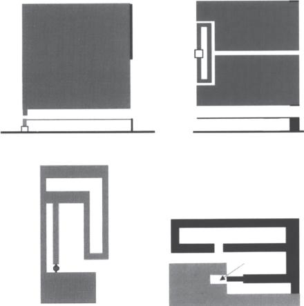
Figure 8.104 Examples of small wire-type RFID antennas ([87], copyright C 2006 IEEE, and [90], copyright C 2006 IEEE).
often called a tag, instead of transponder, because of their physical shape, and they can also function as visual tags for pallets or cases of goods. Other types of antennas can be used in the tag. Antennas in tags, which have generally small, compact, or thin structures, are designed by applying miniaturization techniques.
For the active RFID systems, transponders have an internal power source, typically a battery, by which devices in the interrogator can be triggered for sending signals back to the interrogator. The interrogators are also called readers, because in earlier RFID systems, they were only capable of reading data or information sent from transponders. Varieties of antennas are employed for both transponders and interrogators in the active systems, although small antennas are still preferred. Numerous types of antennas have been developed and employed in practice for various types of RFID equipment. In this section, some typical RFID antennas are described.
8.3.2.1Dipole and monopole types
To reduce the antenna size, meander line structures are widely employed in various types of RFID antennas. Some examples are shown in Figure 8.104 [86]. In the figure, (a) shows an antenna (f = 915 MHz) with a loop to couple with the meander line [87];
(b) depicts a meander line antenna (f = 920 MHz) loaded with a bar, by which antenna impedance can be adjusted along with the meander line length [88]; (c) is a doubly folded L-shaped dipole (f = 915 MHz), useful to fit the corner of a box and being visible from almost every angle [89]; and (d) provides a multi-conductor antenna (f = 900 MHz) having double T-match scheme and spiral folding to achieve the required inductance [90]. There are many other meander line RFID antennas; however, here only a few among them are introduced.
A unique-configuration antenna, named forked shape monopole antenna is proposed in [91]. The antenna is designed for a compact USB dongle application. The geometry of

352 |
Design and practice of small antennas II |
|
|

 FSMA
FSMA
DVB tuner
Figure 8.105 A FSMA installed USB dongle ([91], copyright C 2010 IEEE).
the antenna is illustrated in Figure 8.105. The fork line is used to create a capacitive coupling effect to reduce the antenna size and enhance the bandwidth. The antenna is designed to operate in a very wide frequency band, 470 to 860 MHz, so as to receive digital video broadcasting (DVB). Furthermore, the upper frequency band of the antenna can be extended to 1142 MHz, leading to use in the GSM (Global System for Mobile Communications) band.
A wired bow-tie dipole RFID tag antenna recessed in a cavity is introduced in [92]. Figure 8.106 illustrates antenna geometry with top view in (a) and cut view in (b). The antenna is a cavity-backed type, allowing easy installation in a metallic container, vehicle, aircraft, and so forth. The antenna having the total length of 89 mm and the wing width of 38 mm is designed to operate at 915 MHz and is placed on the surface of the cavity, having the size of 140 × 80 × 50 mm. Through experiment, it was confirmed that maximum reading distance by using the antenna with optimized dimensions was about 3.2 times greater when compared with a commercial label-type RFID tag.
A planar dipole antenna (f = 915 MHz) designed to allow direct mounting on materials often encountered in practical applications is described in [93]. The outer shape of the planar element is an inverse exponential curve, which is illustrated in Figure 8.107. An inductive coil is attached to the input of the antenna to ease matching to an RFID chip that is mounted at the center of the coil. The size of the antenna is 100 × 25 mm. The reflection coefficient was lower than –5 dB from 860 to 960 MHz. The range performance of the antenna was examined when placed on materials such as cardboard, a paper block, plastic, wood, a bottle of tap water, and a glass bottle, in terms of material relative permittivity and the material thickness. It was found that if the tag is placed on materials such as cardboard, plastic, wood or in free space, having lower permittivity and less thickness, the tag range was around 8 m. However, materials of higher permittivity
8.3 Design and practice of PSA |
353 |
|
|
|
yw |
|
|
Metallic wing |
|
|
|
y |
|
|
gy |
|
|
|
Chip |
|
|
yc |
l3 |
d |
a b |
|
x |
|
|
||||
w |
|
|
|
||
|
l1 |
|
gx |
||
|
l4 |
|
|||
|
l2 |
|
|||
|
|
|
xw |
||
|
|
|
|
|
|
|
|
|
|
Cavity |
|
|
|
xc |
|
|
|
|
|
(a) |
|
|
|
|
Substrate (εr) |
z |
|
Metallic wing |
|
xw |
|
|
|||
|
|
|
|
|
|
|
|
|
|
|
x |
zc |
h |
|
|
|
|
Bow-tie |
|
Chip |
|
|
|
|
antenna |
|
|
Air |
Cavity |
|
|
|
|
|
|
|
|
xc |
|
|
|
|
|
(b) |
|
|
|
Figure 8.106 Geometry of wired bow-tie RFID tag antenna: (a) top view and (b) cut view ([93], copyright C 2010 IEEE).
100 mm
25 mm
y
z  x
x
Silver ink |
Paper |
Aluminum coil |
RFID chip |
Figure 8.107 A flared planar dipole antenna loaded with an RFID reader ([93], copyright C 2010 IEEE).
and greater thickness such as thick paper block, bottle of tap water, glass bottle either empty or filled with water, affect the tag range and decrease it to about 2 m.
8.3.2.2Inverted-F configuration antennas
To reduce the length of a monopole antenna the element is folded, and to ease the impedance matching, a shorting pin is added to form an Inverted-F (IF) shape. Various