


 B
B 
 1-mm thick plastic housing
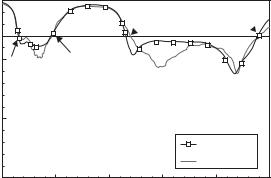


8.1 FSA (Functionally Small Antennas) |
301 |
|
|
L
|
|
|
|
|
|
|
|
|
|
|
|
|
|
|
|
L |
|
|
|
|
|
(a) |
|
|
|
|
|
|
(b) |
|||
|
h |
|
|
|
|
|
|
|
|
h |
|
|
|
|
|
|
|
|
|||
|
|
|
|
|
|
|
|
|
|
|
|
|
|
|
|
|
|
|
|
|
|
|
|
|
|
L |
|
|
|
L |
||
|
|
|
|
|
|
|
|
|||
|
|
|
|
|
|
|
|
|
|
|
(c) |
(d) |
α
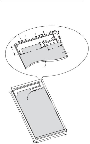
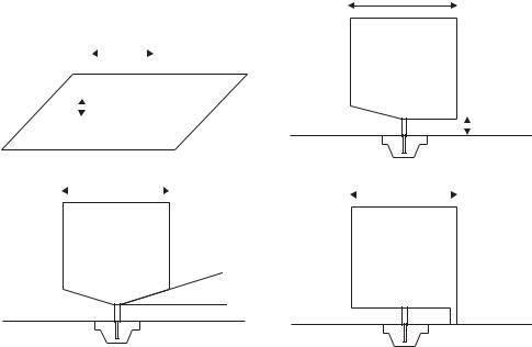
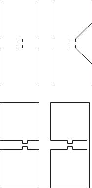
Figure 8.43 Square planar monopole: (a) on the ground plane, (b) with asymmetric beveling,
(c) with symmetrical beveling, and (d) with a shorting post ([20], copyright C 2003 IEEE).
consideration as an important subject when the antenna is designed. The SAR values are calculated by using the simulator SEMCAD for a case where the proposed antenna is mounted at the bottom of the system circuit board. By using the input power of 24 dBm for the GSM 850/900 and 21 dBm for the GSM 1800/1900, UMTS, and LTE operations, the SAR values per gram of head tissue are obtained all well below the SAR value limit of 1.6 W/kg. This result indicates that the proposed antenna can be employed in mobile phone handsets without any concern over effect of radiation from the mobile phone.
8.1.2.1.2.2 Wideband antennas 8.1.2.1.2.2.1 Planar monopole antennas
A planar quarter-wavelength monopole is a simple wideband antenna, which is generally convenient to match to 50 with unbalanced feed, and does not require a balun. The planar monopole antenna was first described briefly in the literature in 1968 [20] and more detail was given in 1976 in [21], where wide impedance characteristics of a planar quarter-wave monopole were discussed. Subsequently studies on planar monopoles have continued, dealing with various types and shapes of antennas theoretically and experimentally. Among them, an example was that a disk-shaped planar monopole had shown return loss greater than 10 dB over an impedance bandwidth ratio in excess of 10 to 1 [22]. One of the simplest typical planar shapes is a square monopole vertically standing on the ground plane as shown in Figure 8.43, which depicts (a) the

302 |
Design and practice of small antennas II |
||||||||
|
|
|
|
|
|
|
|
|
|
|
|
|
|
|
|
|
|
|
|
|
|
|
|
|
|
|
|
|
|
|
|
|
|
|
|
|
|
|
|
a s  l
l 


h
w1 
 w2
w2
 wt
wt
d
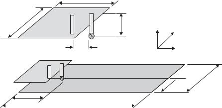
Figure 8.44 Geometry of a folded loop [27b].
basic geometry, (b) modified versions at its bottom side with asymmetrical beveling,
(c) with symmetrical beveling, and (d) with a shorting post. There have been various planar geometries such as rectangle, trapezoid, triangle, and so forth [23–25].
In practical applications, a conventional monopole structure, comprising an antenna standing vertically on the ground plane, is not preferable, because it usually requires an infinite or comparable ground plane, leading to increasing the antenna volume, contrary to the need to make the antenna small and compact. The recent trend is to use planar monopole structures, comprised of the antenna and the ground plane being placed in the same plane. By this means the antenna size can be reduced, granted that the size of ground plane is reduced. To maintain the wide bandwidth with reduced-size ground planes, various techniques have been developed. Antenna profiles can be all sorts of planar geometries; disk, rectangle, triangle, ellipse, and so forth. Some of them will be described later.
8.1.2.1.2.2.2 Folded loop antenna
The folded loop antenna was initially designed as an antenna having a balanced structure and fed by a balanced line to suppress the current flowing into the ground. This is important in portable devices in order to mitigate the body effect on the antenna performance, produced by the current on the ground plane, which is perturbed by the operator’s hand and head [26].
The antenna is fabricated by folding a long thin rectangular loop of total one wavelength to form a half-wavelength folded dipole, which appears as a folded two-wire transmission line as illustrated in Figure 8.44 [27a]. The antenna is effectively divided into two parts; a dipole structure and a two-wire transmission line. The dipole part essentially contributes to radiation while the two-wire transmission line plays a significant role for determining the antenna impedance [27b] (refer to Appendix I following this
8.1 FSA (Functionally Small Antennas) |
303 |
|
|
|
coaxial |
two-wire |
|
|
cable |
line |
|
z |
|
|
|
y |
(b) unbalanced |
(a) balanced |
|
system |
system |
||
|
36.3
36.3
1
119.4 |
Unit [mm] |
2.1 |
|
Figure 8.45 Geometry of the folded loop placed on the ground plane [27b, 28].
d |
|
0 |
|
|
|
|
d |
|
0 |
|
|
|
|
|
|
||||
|
|
|
|
|
|||||
|
|
|
|
|
|
|
|
+ |
|
d |
|
0 |
|
|
+
λ1/2 |
+ |
+ |
λ2/2 |
+ |
+ |
λ3/2 + − |
|
|
|||||
|
|
|
|
|
|
|
|
|
|
|
|
|
|
|
+ |
|
|
|
|
|
|
|
+ |
|
|
|
|
|
|
|
|
|
|
|
|
|
|
|
|
|
|||
|
|
|
|
|
|
|
|
|
|
|
|
|
|
|
|
|||
|
|
|
|
|
|
|
|
|
|
|
|
|
|
|||||
|
|
|
|
|
|
|
|
|
|
|
|
|
||||||
|
|
|
|
|
|
|
|
|
|
|
||||||||
|
|
|
|
|
|
|
|
|
|
|
|
|
|
|
|
|
|
|
(a) f/f0 = 0.80 |
|
(b) f/f0 = 1.01 |
|
(c) f/f0 = 1.21 |
||||||||||||||
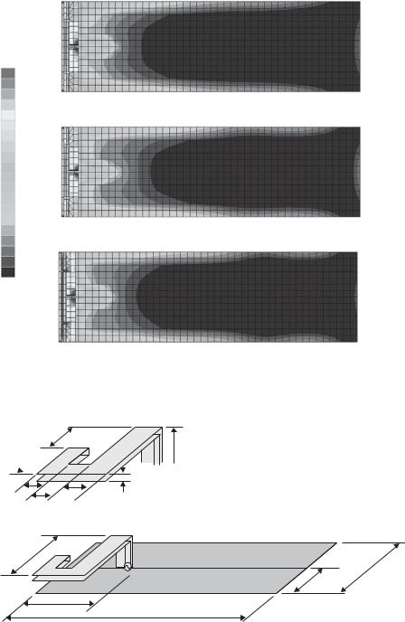
Figure 8.46 Current distributions for resonance on the folded loop element ([27b, 28], copyrightC 2001 IEICE).
section). The antenna is typically mounted on a ground plane in small equipment as shown in Figure 8.45, in which feeding structure is depicted in the inset, and dimensions are given as an example when the antenna is used for a typical mobile phone handset using finite ground plane [27c].
With this antenna structure, resonance occurs at several frequencies as several current modes are observed on the antenna elements, which are depicted in Figure 8.46. Resonances occur at (a) the first frequency f1 = 0.80 f0, (b) the second frequency f2 = 1.01 f0, and (c) the third frequency f3 = 1.21 f0, where f0 is the center frequency of the frequency band [27c]. It was found that a wideband performance was obtained as a result of combined excitation of three closely separated frequencies. Calculated and measured VSWR characteristics when the center frequency f0 is 3470 MHz are shown in Figure 8.47, which indicates a wide bandwidth covering from 0.8 to 1.2 f / f0 for VSWR
8.1 FSA (Functionally Small Antennas) |
305 |
|
|
0 dB |
|
−2 dB |
|
−4 dB |
|
−6 dB |
(a) f/f0 = 0.80 |
−8 dB |
|
−10 dB |
|
−12 dB |
|
−14 dB |
|
−16 dB |
|
−18 dB |
|
−20 dB |
|
−22 dB |
|
−24 dB |
|
−26 dB |
|
−28 dB |
|
−30 dB |
(b) f/f0 = 1.01 |
−32 dB |
|
−34 dB |
|
−36 dB |
|
−38 dB |
|
−40 dB |
|
(c) f/f0 = 1.21
Figure 8.48 Current distributions on the ground plane: (a) f/f0 = 0.80, (b) f/f0 = 1.01, and
(c) f/f0 = 1.21 ([27][28], copyright C 2001 and 2002 IEICE).
s
h
wt 


 b
b
w1 |
w2 |
d |
|
18.85 |
|
|
36.3 |
|
17.4 |
15.0 |
Unit [mm] |
|
119.4 |
Figure 8.49 BFMA configuration and the antenna on the ground plane (w1 = w2 = 5, wt = 1.5, b = 0.5, h = 7, s = 12 [mm]) [27b].
306 |
Design and practice of small antennas II |
|
|
|
a |
|
b |
h |
Z |
|
||
|
|
|
|
|
Y |
d |
|
X |
|
|
 36.3 17.4
15.0 |
Unit (mm) |
119.4
Figure 8.50 PIFA for comparison (a = b = 19.5, d = 5, h = 7 [mm]) [27b].
operating with a power spectrum below –41.6 dBm. Since those systems operate with relatively low power, the communication link is limited to a short range and equipment is generally constructed in small size. Hence, antennas to be installed in such small equipment should accordingly be small. However, since the systems are designed for using signal transmissions that concern high-data-rate information, new challenges are imposed to develop small antennas yet having wideband.
Preferred antenna types to be used for UWB systems are planar ones with small dimensions, yet being simple, compact, low cost, and of course having appropriate performances that satisfy the system operation. In many cases electrically small antennas (ESA) with wideband features are required. Since conventional ESAs have generally narrow bandwidths, development of such small wideband antennas needs additional considerations beyond the techniques used to develop conventional ESAs. The simplest technique to produce wide bandwidth is full use of an area for the radiator, or generation of multiple resonances at closely spaced frequencies within a single antenna structure. For this purpose, a planar structure is fully used as a radiator, and current paths on the antenna surface are modified by modifying antenna shape and introducing slots/slits on the surface of the antenna. How to obtain a wide bandwidth with small-sized antennas is another serious problem. Reduction of the antenna size is attained not only by reduction of radiator size, but also reduction of the ground plane size. It should be noted that since the ground plane in small antennas often acts as a part of the radiator when the feeding system of the antenna is an unbalanced structure, and influences the radiation performance, special considerations to achieve required antenna performance are needed. An application of a DGS (Defected Ground Structure) concept can be one of the candidates. The DGS technique will be described in the next section, because it is a modified version of an EBG (Electromagnetic Band Gap) and exhibits bandgap properties and slow-wave effects that help to reduce the ground-plane size.
Planar structure is advantageous in applying antennas to very small equipment, as it can be easily embedded on a printed circuit board or integrated with other RF electronic
308 |
Design and practice of small antennas II |
|
|
(Gap = 0.08)
172.2°
6.80
3.07 |
3.99 |
|
2.80 R 4.00
8.40
4.20
(a)
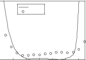
VSWR
20
FE-BI 15 
 Measured
HFSS
10 |
|
|
|
|
5 |
|
|
|
|
0 |
0.4 |
0.6 |
0.8 |
1 |
0.2 |
Frequency (GHz)
(b)
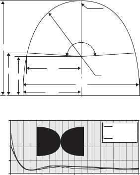
Figure 8.52 Initial flare dipole (a) Geometry and dimensions (in inches) and (b) shaped dipole and frequency characteristics ([33], copyright C 2009 IEEE).
Impedance bandwidth for S11 < –10 dB of these antennas are: A: 3.60–8.21, B: 3.40– 10.17, C: 3.61–15.30, and D: 2.87–10.04 (in GHz). In terms of bandwidth, antenna C has widest, while antenna A has the narrowest. In addition, antenna C exhibits the most stable impedance response compared with other types. Antenna D introduces an additional resonance at about 2.7 GHz due to the shorting pin, which also provides inductive reactance below 2.7 GHz, while other types are capacitive.
8.1.2.1.2.3.1.2 A flare dipole with shape optimized using splines
A novel planar wideband antenna capable of operating from 190 MHz to 1000 MHz with gains greater than 0 dBi (having size λ/5 × λ/7 at 190 MHz) is introduced in [33a]. The initial flare dipole has the outer curve which draws a 172.2◦ arc with 4 inches radius, being connected to a trapezoid as is depicted in Figure 8.52(a), where dimensions in inches are given. Bandwidth characteristics of the initial flare dipole are also shown. The shaped dipole is depicted in Figure 8.52(b), which has dimensions of 13.68 inches long (including the gap) and 8.40 inches wide, corresponding to λ/3 × λ/5 at 280 MHz. Although the initial flare dipole has wide bandwidth of 3.5:1 (280 to 1000 MHz) as shown in Figure 8.52(b), further wide bandwidth of 5.25:1 (190 to 1000 MHz) is targeted and