224 |
Design and practice of small antennas I |
|
|
0 |
|
|
|
|
|
|
|
|
–5 |
|
|
|
|
|
|
|
|
–10 |
|
|
|
|
|
|
|
|
–15 |
|
|
|
|
|
|
|
|
–20 |
|
|
|
|
|
|
|
|
–25 |
|
|
|
|
ωp = 0.707 GHZ |
|
|
|
|
|
ωp = 1.286 GHZ |
|
–30 |
|
|
|
|
|
|
|
|
0 |
0.5 |
1 |
1.5 |
2 |
2.5 |
3 |
3.5 |
4 |
Frequency (GHZ)
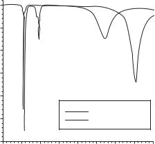
Figure 7.215 Return-loss characteristics for even-mode (solid line) and odd-mode (dotted line) excitation of the elliptical patch antenna ([113], copyright C 2010 IEEE).
case. This is an attribute of the MNG material with μ1 = –5.618 at 0.5 GHz, and –1 at 0.91 GHz, respectively, obtained by using the Drude dispersion relation (7.72) with the magnetic plasma frequency ωmp = 1.286 GHz and 0.707 GHz, respectively. These correspond to the excitation of both the first odd and second even modes in the spectrum. In these cases, ε1 = 2ε0 is used. At higher frequencies, resonances with broader bandwidth are observed. These correspond to standard patch resonances for even mode (at 2.67 GHz) and odd mode (at 3.65 GHz) with μ1 = μ0, as the substrate permeability turns to become positive.
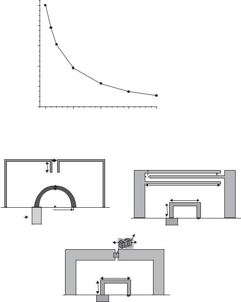
Realization of artificial MNG material may be approached with a technique introduced in the previous section employed for the circular patch [112]. Properly designed MSRR or MSR may perform similar magnetic resonance within a sub-wavelength volume, consistent with the miniaturized size of an antenna. Gain varies depending on the magnetic plasma frequency. The calculated gain normalized to the case of an ideal lossless MM at the resonance frequency (0.5 GHz) is shown in Figure 7.216. In this case, mismatch loss at the feed is excluded and only the effect of MM absorption, which concerns the damping frequency ωτ is included.
7.2.5.1.1.3 Small loop loaded with CLL
Artificial materials exhibiting negative mu implemented by Capacitive-Loaded Loops (CLL) are employed for miniaturization of a loop antenna [109]. The MNG interacts with the highly inductive near field produced by a small loop to attain resonance and also obtain matching in space, even though the antenna has an electrically small size, that is, ka ≤ 0.5 (a: radius of a sphere circumscribing the maximum size of antenna). Some examples, using a semi-circular loop and a rectangular loop, are illustrated in Figure 7.217, which shows use of different types of capacitance in the CLL: (a) a spacing between a loop, (b) an inter-digital capacitor, and (c) a lumped component. Various types of antennas with different geometries and dimensions are designed, and
7.2 Design and practice of ESA |
225 |
|
|
|
0 |
|
|
|
|
(dB) |
–2 |
|
|
|
|
|
|
|
|
|
gain |
–4 |
|
|
|
|
|
|
|
|
|
Normalized |
–6 |
|
|
|
|
|
|
|
|
|
|
–8 |
|
|
|
|
|
–10 |
|
|
|
|
|
0 |
250 |
500 |
750 |
1000 |
|
|
Damping frequency ωτ (MHZ) |
|
Figure 7.216 Gain normalized to the case of an ideal lossless MM at the resonance frequency with respect to the damping frequency ([113], copyright C 2010 IEEE).
|
Spacing |
Finger |
Finger |
Finger |
Stub |
|
|
gap |
width |
spacing |
length |
|
|
|
|
|
Wire radius |
|
|
|
(a) |
|
(b) |
Finger length |
|
|
|
|
Antenna length |
|
Coaxial |
|
Antenna |
|
|
Antenna radius |
height |
|
|
feed |
|
|
|
|
Antenna width |
|
|
|
|
|
Ceramic dielectric |
|
|
Lumped RLC |
Terminal electrode |
|
boundary |
|
|
(c) |
Antenna length |
Antenna |
height |
Antenna width
Figure 7.217 Examples of small antenna combined with CLL having a capacitance of (a) a spacing between the loop, (b) an inter-digital capacitor, and (c) a lumped component ([109], copyright C 2008 IEEE).
their simulated performances (radiation efficiency, bandwidth, and Q, and so forth), in terms of their geometrical parameters and frequencies from 300 MHz to 6 GHz, are introduced. High radiation efficiency is obtained in most of the antennas even though the antennas have electrically small size, whereas the VSWR bandwidth is found to be generally very narrow, as low as 4% at maximum.
226 |
Design and practice of small antennas I |
|
|
Negative permittivity resonator
Stub
a
Coax
Ground plane
Figure 7.218 A stub antenna loaded with a semi-sphere ENG MM ([114], copyright C 2006 IEEE).
Figure 7.219 (a) Folded spherical helix resonator and (b) spherical-capped dipole, ([114], copyright C 2006 IEEE).
7.2.5.1.2 Epsilon-Negative Metamaterials (ENG MM)
ENG MMs can be employed for miniaturizing antennas as well as MNG MMs. However, because ENG MMs are available either in the optical frequency regions or using plasmas of the appropriate charge density, applications of ENG MM to antennas at microwave frequencies are confined to use of artificial materials. The representative artificial material is a periodical arrangement of conductors introduced in [101, 102].
An ENG MM applied to a small antenna to increase the bandwidth (lowering Q) and raising the efficiency is demonstrated in [114]. A negative permittivity metamaterial (i.e. ENG MM) of a semi-sphere is placed on a ground plane and fed through its center by a coaxial transmission line terminated with a small monopole stub as shown in Figure 7.218. By this geometry, electric field distribution within the sphere is uniform at the fundamental resonant mode and thus the small stub protruding into the center of the sphere provides a strong coupling between the coaxial transmission line mode and the resonant mode of the sphere. Through the analysis, it is shown that the spherical resonator composed of a semi-spherical ENG MM has a Q that is only 1.5 times the Chu limit. This is comparable to the performance of the other types of small spherical antennas such as a folded spherical helix (Figure 7.219(a)) and a spherical-capped dipole (Figure 7.219(b)), which have Q nearly 1.5 times the Chu limit, even with the size as
7.2 Design and practice of ESA |
227 |
|
|
(c)
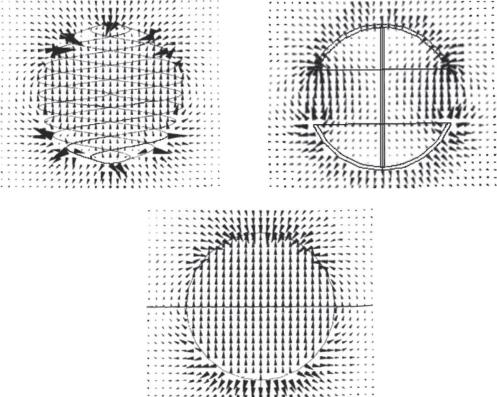
FIGURE 7.220 Electric field distribution profiles (a) folded spherical helix, (b) spherical-capped dipole, and (c) ENG sphere ([114], copyright C 2006 IEEE).
small as around ka = 0.3. These verify the work of Wheeler, mentioning that optimal use of the sphere volume occupying an antenna may provide optimized bandwidth for the antenna, even though with electrically small size. The electric field distribution profiles of these three types are shown in Figure 7.220 [114], which shows for a case of
(a) spherical helix, (b) spherical-capped dipole, and (c) ENG MM loaded semi-sphere. There is a similarity in the behavior of modes between that of the helix and that of the ENG MM sphere.
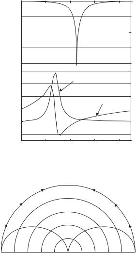
Simulation for the antenna model shown in Figure 7.218 is performed by using these parameters: 8 mm for the radius of the semi-sphere, 3 mm for the length of stub, which is optimized for good impedance matching, and the plasma frequency of 3.54 GHz for the ENG MM that obeys the Drude dispersion relation. The stub length 3 mm corresponds to λ/50 and the overall antenna size is characterized by ka = 0.34 (radius a = λ/18.5, where λ = 148 mm; the resonance frequency at 2025 MHz). Calculated return loss, and impedance are shown in Figure 7.221(a) and (b), respectively. Figure 7.222 depicts the simulated radiation pattern, which resembles that of an ordinary small monopole on the ground plane.
228 |
Design and practice of small antennas I |
|
|
–10
3 mm stub
8 mm half-sphere
–20
–30
λ = 148 mm
–40
(a)800
|
|
|
Resistance |
|
(dB) |
600 |
|
|
|
|
400 |
|
|
|
|
loss |
|
|
Reactance |
|
|
|
Return |
200 |
|
|
|
|
|
|
|
|
|
|
0 |
|
|
|
|
|
–200 |
|
|
|
|
|
1800 |
1900 |
2000 |
2100 |
2200 |
|
|
|
Frequency (MHZ) |
|
Figure 7.221 (a) Return loss and (b) impedance ([114], copyright C 2006 IEEE).
180 |
|
|
|
|
0 |
0 |
0.2 |
0.4 |
0.6 |
0.8 |
1 |
Output power (linear, normalized)
Figure 7.222 Radiation pattern ([114], copyright C 2006 IEEE).
An ENG MM can be implemented by using an LH TL structure [115]. A compact TL MM antenna consisting of two unit cells, each of which comprises a microstrip TL loaded with five spiral inductors, is introduced in [115]. The antenna is illustrated in Figure 7.223, in which are shown (a) 3D schematic and (b) top view photograph of the fabricated antenna. Each of two arms works independently at its own frequency and corresponding to two frequencies designed to be merged into one passband so that wideband performance can be obtained. The TL MM unit cell employs a round spiral inductor (Figure 7.224(a)), which has dimensions of d × d = 4.5 mm × 4.5 mm. The spiral element is connected to the ground through a via, to form a shunt inductance with a larger inductance, and is equivalently represented by a circuit shown in Figure 7.224(b),
7.2 Design and practice of ESA |
229 |
|
|
Shunt inductor Lo
Via
Coaxial
feed
Figure 7.223 The proposed two-arm TL-MM antenna with compact size and enhanced bandwidth:
(a) 3D schematic and (b) top view photograph ([115], copyright C 2009 IEEE).
10 |
|
|
|
|
|
|
|
|
|
|
|
Circuit |
8 |
|
|
|
|
HFSS |
6 |
|
Z0, |
θ/2 |
Z0, θ/2 |
|
|
|
|
4 |
|
|
|
|
|
|
2 |
|
|
L0 |
|
|
|
|
|
|
|
|
|
0 |
30 |
60 |
90 |
120 |
150 |
180 |
10 |
βd
(b)
Figure 7.224 Spiral-inductor-loaded TL-MM unit cell: (a) geometry of the cell and (b) transmission line representation ([115], copyright C 2009 IEEE).
in which the dispersion characteristics are shown, and Z0 and θ denote the TL characteristic impedance and the electrical length per cell, respectively. The TL MM can
be considered equivalently as an ENG MM with the corresponding plasma frequency fsh
√
given by 1/(2 π L0C), where L0 is a combined inductance of the spiral and the via, and C is the intrinsic capacitance of the TL. The metallic area of the antenna (Figure 7.223) is 22.5 mm × 13.5 mm and the size of the ground plane is 50 mm × 50 mm. The return-loss (–10 dB) bandwidth is about 100 MHz from 3.23 to 3.33 GHz, as a consequence of two resonances merged into the frequency range of 3.25 to 3.30 GHz. The radiation pattern is similar to that of a short monopole. Measured directivity and gain, respectively, are 2.61 dBi and 0.79 dBi, giving an efficiency of 65.8%. Effective extension of the bandwidth achieved by using a two-resonance TL MM with a small size is recognized by the comparison with a single patch antenna having the same bandwidth, which has a larger size than the TL MM antenna.
230 |
Design and practice of small antennas I |
|
|
Antenna width
Antenna height
Via height 
Printed
monopole Coaxial z
feed
x y
Figure 7.225 Planar meander-line structure (an ENG equivalence) combined with a short monopole ([109], copyright C 2008 IEEE).
z
Metal thickness
Pitch length
Monopole antenna
length Helix width
y
x
Coaxial
feed
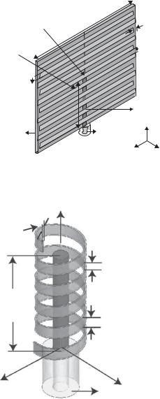
Figure 7.226 Cylindrical helix strip (an ENG equivalence) combined with a short monopole ([109], copyright C 2008 IEEE).
Other examples of ENG MM applications to small antennas are use of a planar meander line structure and a cylindrical helix combined with a small monopole as shown in Figure 7.225 and Figure 7.226 [109], respectively. These planar meander line structure and cylindrical helix strip provide inductance effectively to interact with highly capacitive fields near the electrically small monopole to obtain matching in space. The behavior is similar to that of the ENG MM.