

Acknowledgements
The authors would like to express their highest appreciation to a number of people who assisted them to complete this book, providing useful information, data, and materials related with small antennas, contributing to prepare manuscripts and endeavoring to produce the book through sincere effort.
Particular acknowledgement should go to Dr. J. R. Copeland, who supported us with his editing skill being devoted to our manuscripts, and improved our nonnative English, especially from a technical point of view as an experienced antenna researcher. (He was one of the members who did pioneering work on the active integrated antennas at the Ohio State University Antenna Laboratories in the early 1960s, where the first author was also one of the members.)
The book wouldn’t have been completed without the continuous support and patience of Cambridge University Press editorial and production staff. Sarah Marsh and many other editorial staff assisted us to produce and arrange our manuscripts. We paticularly acknowledge the support of Dr Julie Lancashire, Publisher, Engineering, who at first showed interest in publishing this book, then promoted the book project, and encouraged us in the process of production. She is especially thanked for her patience at the time when the progress of the project stalled, by understanding of our situation, especially my health condition and unavoidable complications caused by the unexpected huge disaster in north-eastern Japan on March 11, 2011. The authors are also deeply indebted to Jon Billam for his kind review of the manuscripts in detail, by which the manuscript was greatly improved and refined.
Kyohei Fujimoto would personally like to thank many people for their assistance and contribution to preparing manuscripts. Among them, immense appreciation should go to Professor Hiroyoshi Yamada, Niigata University, Japan, who generously helped in producing figures and tables in Chapters 6, 7, and 8 with hearty cooperation of not fewer than 10 of his students who worked excellently under his instruction. We are also much obliged to Dr. Yongho Kim, Nguyen Tuan Hung, and Yuki Kobayashi, current and former graduate students of Professor H. Morishita, who assisted us by exhibiting their skillful work, in drawing figures in Chapters 1 to 4, improving poor quality figures in some few chapters, and producing Chapter 11. Last but not least, I must acknowledge my wife Machiko Fujimoto, who allowed me to continue to work on the book by sacrificing much domestic life, with patience for a couple of years until completion of the book.

Acknowledgements xv
Hisashi Morishita would like to thank all his graduate students of his laboratory in National Defense Academy, Japan for their wholehearted cooperation in producing figures and tables in Chapters 9 and 10. Especially, Dr. Y. Kim, who was his graduate student, who contributed to produce Chapter 10.

1 Introduction
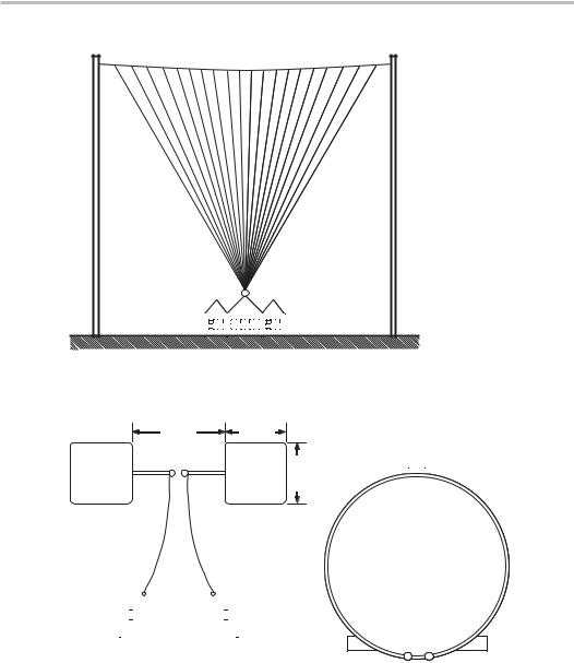
The antenna first used in radio communication was a small antenna, which was a fantype monopole (Figure 1.1), developed by G. Marconi, used for trans-Atlantic Ocean communication in 1901 [1]. The antenna appeared to be very large, as it was hung by two masts 48 meters high and 60 meters apart so that it could never be considered small [1]; however, since the dimensions were a small fraction of wavelength (about 1/6 of the operating wavelength, 366 meters), it was “electrically” small.
An Electrically Small Antenna – ESA – (the definition is described in 2.1) is an antenna of dimensions much smaller than the wavelength. In the classical sense, there are two types of ESA; one is an electric element, which couples to the electric field and is referred to as a capacitive antenna, and another is a magnetic element (electric loop), which couples to the magnetic field and is referred to as an inductive antenna. These are ESA categories; however, many practical antennas are some combination of these two types. It should be noted that small electric and magnetic elements in the forms of dipoles and loops have been used since 1887 when Hertz successfully generated and detected electromagnetic waves and verified Maxwell’s prediction [2]. His invention of such small antennas certainly proved his success in demonstrating existence of electromagnetic waves. Although more than 120 years have passed since Hertz’s experiment, his small dipoles and loops shown in Figure 1.2 (a) and (b) were so basic that essentially the same antennas are still being used.
Typical antennas in practical use for the early days of radio communications were ESAs. Examples of them are shown in Figure 1.3: (a) top-loaded monopole, (b) fan-type monopole, (c) multi-wire, (d) rectangular cage type, and (e) cage type, and so forth. Most of them were installed on ships and operated in frequency bands of LF and HF. Since then, small antennas have been used in various communication systems, particularly mobile systems, where small antennas were required. Antenna types used are not only linear but also planar and others such as composite and integrated types. Antenna technology has made steady progress along with the progress in communication systems and electronic devices, especially during World Wars I and II that provided the need for advanced antenna design and the surge of technology. Operating frequencies have gradually been raised to higher regions; from MF and HF bands to VHF, UHF, and SHF in recent years. Use of higher frequencies and smaller-sized electronic devices gave impetus to develop smaller antennas. One of the major trends in recent antenna technology is miniaturization of antenna systems, yet with improved functioning and further sophistication. The latest applications of small antennas are mainly to mobile communications and newly deployed
2 |
Introduction |
Figure 1.1 The first radio communication antenna used for trans-oceanic communications developed by Marconi in 1901 [1].
60 cm |
40 cm |
|
40 cm |
|
|
|
|
|
|
|
|
|
|
|
|
|
|
|
|
|
|
|
|
|
|
|
|
|
|
|
|
|
|
|
|
|
|
|
|
|
|
|
|
|
|
|
|
|
|
|
|
|
|
|
|
|
|
|
|
|
|
|
|
|
|
|
|
|
|
|
|
|
|
|
|
|
|
|
|
|
|
|
|
|
|
|
|
|
|
|
|
|
|
|
|
|
|
|
|
|
|
|
|
|
|
|
|
|
|
|
|
|
|
|
|
|
|
|
|
|
|
|
|
|
|
|
|
|
(a) |
|
|
|
|
|
(b) |
||||
Figure 1.2 Hertz antenna used for his experiment of the first radio wave transmission experiment [2, 3, 4].
various wireless systems. The typical mobile systems are mobile phone systems, which have evolved from the first generation systems in the early 1950s to the present fourth generation through the third-generation systems and further progressed wireless systems such as smart phones and handy tablets, where small antennas are indispensable. Recently emerged wireless systems also demand small antennas. These recent wireless systems are applied not only to communications, but also to control, sensing, identification, medical use, body communications, and data and video transmission. Typical systems
Introduction 3
(a) |
(b) |
(c) |
(d) |
(e) |
Figure 1.3 Typical antennas used in early radio communications; (a) top-loaded monopole,
(b) fan-type monopole, (c) multi-wire, (d) rectangular cage type, and (e) cage type [2, 3, 4].
for which small antennas are required, are NFC (Near Field Communication) systems, including RFID (Radio Frequency Identification), UWB (Ultra Wideband) systems, and wireless broadband systems such as WLAN (Wireless Local Area Network) systems and WiMAX (Worldwide Interoperability for Microwave Access) systems.
Requirements from various mobile systems have intensely stimulated research and study of small antennas and as a consequence have brought promotion of novel antenna systems development. They have also contributed to improved antenna performances

4 Introduction
Figure 1.4 A millimeter-wave horn antenna, which is physically small, but electrically large.
Patch
Substrate
Ground plane
(a) |
(b) |
Ground plane
(c)
Figure 1.5 Typical planar antennas; (a) PIFA (Planar Inverted-F Antenna), (b) patch antenna, and
(c) MSA (Microstrip Antenna).
year by year and the antenna functions have gradually been enhanced to meet the requirements raised from the advanced systems. Meanwhile, discussions on the fundamentals of small antennas have continued ceaselessly ever since Wheeler’s work, because of continued significance. Problems that concern limitations are still regarded as very interesting and controversial topics. Knowledge of the limitations informs antenna engineers how to approach the limitations with an antenna of given size.
There is some ambiguity in the expression “small antenna,” because one can say, “This is a small antenna,” when it looks physically small. For example, a millimeterwave (MMW) horn antenna (Figure 1.4) of only the size of a human palm looks simply small and it might be called a “small” antenna. However, since a MMW antenna often has the aperture of a few or more wavelengths, the antenna dimension shouldn’t be said to be “small,” but in fact “electrically large” in terms of the operating wavelength. On the contrary, for an antenna having dimensions of a small fraction of the operating wavelength like the Marconi antenna mentioned earlier, the antenna is referred to as an “electrically small” antenna. Here, small antennas will be treated in a wider sense, in

Introduction 5
|
|
(a) |
|
|
|
|
|
|
|
|
(b) |
|
|
|
|
|
|
|
|
|
|
|
|
|
|
|
|
|
|
|
|
|
|
|
|
|
|
|
|
|
|
|
|
|
|
|
|
|
|
|
|
|
|
|
|
|
|
|
|
|
|
|
|
|
(c) |
(d) |
Figure 1.6 Typical linear small antennas; (a) NMHA (Normal Mode Helical Antenna), (b) Meander Line Antenna, (c) ILA (Inverted-L Antenna), and (d) IFA (Inverted-F Antenna).
Monopole |
Slot |
(a) |
(b) |
Figure 1.7 Examples of composite antenna; (a) self complementary antenna and (b) active integrated antenna.
which antennas are defined four ways; first, in terms of simply physical size; second, in comparison with the operating frequency; third, in relation with function; and fourth, in the size-constrained structure. Small antennas defined in terms of the function may be unfamiliar in general; however, antennas so defined should be appreciated as a significant concept that comprehensively embraces the term “small.”
Various types of small antennas have so far been evolved from simple dipoles or loops. Planar and low-profile antennas are typical ones. Practical examples are illustrated in Figure 1.5, which shows (a) Planar Inverted-F Antenna (PIFA), (b) patch antenna and
(c) Microstrip Antenna (MSA). Meanwhile, examples of linear antennas are shown in Figure 1.6, which depicts (a) Normal Mode Helical Antenna (NMHA), (b) Meander

6 Introduction
(a) |
(b) |
Figure 1.8 Examples of loaded antenna: (a) a ferrite loaded coil, and (b) dielectric loaded patch antenna.
Negative permittivity resonator
Stub
Coax
Ground plane
Figure 1.9 Example of metamaterial (negative permittivity) loaded small antenna [5–7].
Line Antenna (MLA), (c) Inverted-L Antenna (ILA), (d) Inverted-F Antenna (IFA) and composite antenna. Examples of composite antennas are shown in Figure 1.7, which depicts (a) an example of complementary antennas and (b) an example of active integrated antennas. Integration technique, by which some device or circuitry is combined with an antenna structure so that the antenna works with enhanced performance or function, can be utilized for small-sizing. Application of materials such as ferrite and/or dielectrics is also a useful means to reduce antenna size. Examples are an antenna loaded with a ferrite and an MSA loaded with dielectric material as shown in Figure 1.8(a) and (b), respectively. Presently, introduction of metamaterials such as mu-negative or epsilon-negative materials (MNM or ENM) and double negative materials (DNG) into the antenna structure has been discussed extensively worldwide as one of the promising candidates for antenna miniaturization [5–13]. An example of application of negativeepsilon material to small antenna structure is depicted in Figure 1.9 [6]. Development of negative-mu materials will also contribute to new small antennas [14]. These antennas will be discussed in later sections.
References
[1]J. Ramsay, Highlight of Antenna History, IEEE Antennas and Propagation Society Newsletter, December 1981, 8.
[2]S. Tokumaru, Invitation to Radiowave Technology, Kohdansha, Japan, 1978, pp. 48–50 (in Japanese).

References 7
[3]O. Lodge, Signaling Across Space Without Wires, Van Nostrand, 1900.
[4]G. Pierce, Principles of Wireless Telegraphy, McGraw-Hill, 1910.
[5]H. R. Stuart and A. Pilwerbetsky, Electrically Small Antenna Elements Using Negative Permittivity Resonator, IEEE Transactions on Antennas and Propagation, vol. 54, 2006, no. 6, pp. 1644–1653.
[6]F. Bilotti, A. Ali, and L. Vegni, Design of Miniaturized Metamaterial Patch Antennas with
µ-Negative Loading, IEEE Transactions on Antennas and Propagation, vol. 56, 2008, no. 6,
pp.1640–1647.
[7]P. Y. Chen and A. Alu, Sub-Wavelength Elliptical Patch Antenna Loaded with µ-Negative Permittivity Resonator, IEEE Transactions on Antennas and Propagation, vol. 58, 2010, no. 1,
pp.13–25.
[8]N. Engheta and R. W. Ziolkowsky, eds., Metamaterials-Physics and Engineering Explorations, IEEE Press, 2006, John Wiley and Sons.
[9]A. Lai, C. Caloz, and T. Itoh, Composite Right/left-Handed Transmission Line Metamaterials, IEEE Microwave Magazine, September 2004, pp. 34–50.
[10]C. Caloz, T. Itoh, and A. Rennings, CRLH Metamaterial Leaky-Wave and Resonant Antennas, IEEE Antennas and Propagation Magazine, vol. 50, 2008, no. 5, pp. 25–39.
[11]G. V. Eleftheriades and K. G. Balmain (eds.), Negative Refraction Metamaterials: Fundamental Principles and Applications, Wiley-IEEE Press, 2005.
[12]J. L. Volakis, C.-C. Chen, and K. Fujimoto, Small Antennas, Miniaturization Techniques and Applications, McGraw-Hill, 2010, chapter 6.
[13]F. Capolino (ed.), Applications of Metamaterials, CRC Press, 2009, Part IV.
[14]T. Tsutaoka, et al., Negative Permeability Spectra of Magnetic Materials, IEEE iWAT 2008, Chiba, Japan, P202, pp. 279–281.