

28 ANESTHESIA MACHINES
13.Ford A. Choosing cost-efficiency in low-volume labs. CAP today 2003; June 32–52.
14.Markin RS. Clinical laboratory automation. In: Henry JB, editor. Clinical diagnosis and management by laboratory methods. Philadelphia: W.B. Saunders; 2001.
15.Ford A. Laboratory automation systems and work cells. CAP today 2003; May: 35–52.
16.Sasaki M. Completed automatic clinical laboratory using a sample transportation system: the belt-line system. Jpn J Clin Pathol 1984;32:119–126.
17.NCCLS laboratory automation: specimen container/specimen carrier; proposed standard. NCCLS document auto 1 P; December 1995.
18.NCCLS laboratory automation: bar codes for specimen container identification; proposed standard. NCCLS document 2 P; April 1999.
19.NCCLS laboratory automation: communications with automated clinical laboratory systems, instruments, devices and information systems; proposed standard. NCCLS document 3 P; December 1998.
20.NCCLS laboratory automation: systems operational requirements and information elements; proposed standard. NCCLS document auto 4 P; October 1999.
21.NCCLS laboratory automation; electromechanical interface; proposed standard. NCCLS document auto 5 P; April 1999.
22.Markin RS, Whalen SA. Laboratory automation; trajectory, technology and tasks. Clin Chem 2000;46:764–771.
23.Sarkozi L, Simson E, Ramanathan L. The effects of total laboratory automation on the management of a clinical chemistry laboratory. Retrospective analysis of 36 years. Clinica Chimica Acta 2003;329:89–94.
See also BLOOD COLLECTION AND PROCESSING; COMPUTERS IN THE BIOMEDICAL LABORATORY; CYTOLOGY, AUTOMATED; DIFFERENTIAL COUNTS,
AUTOMATED.
ANALYZER, OXYGEN. See OXYGEN ANALYZERS.
ANESTHESIA MACHINES
ROBERT LOEB
University of Arizona
Tuscon, Arizona
JEFFREY FELDMAN
Children’s Hospital of
Philadelphia
Philadelphia, Pennsylvania
INTRODUCTION
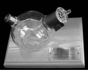
On October 16, 1846, W. T. G. Morton gave the first successful public demonstration of inhalational anesthesia. Using a hastily devised glass reservoir to deliver diethyl ether, he anesthetized a patient before an audience at the Massachusetts General Hospital (Fig. 1). This glass reservoir thus became the first, crude, anesthesia machine. The technology of anesthesia machines has advanced immeasurably in the ensuing 150 years. Modern anesthesia machines are used to administer inhalational anesthesia safely and precisely to patients of any age, in any state of health, for any duration of time, and in a wide range of operating environments.
Figure 1. AreproductionoftheMortonInhaler, 1850. (Image#by the Wood Library-Museum of Anesthesiology, Park Ridge, Illinois.)
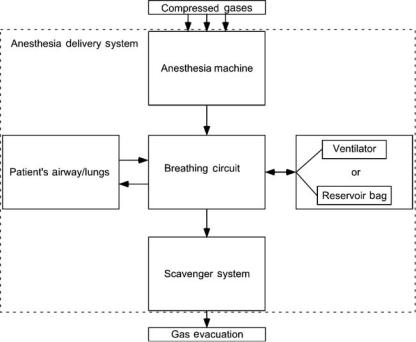
The term anesthesia machine colloquially refers to all of the medical equipment used to deliver inhalational anesthesia. Inhalational anesthetics are gases that, when inhaled, produce a state of general anesthesia, a drug-induced reversible loss of consciousness during which the patient is not arousable, even in response to painful stimulation. Inhalational anesthetics are supplied as either compressed gases (e.g., nitrous oxide), or volatile liquids (e.g., diethyl ether, sevoflurane, or desflurane). In recent years, the anesthesia machine has been renamed the anesthesia delivery system, or anesthesia workstation because modern devices do more than simply deliver inhalational anesthesia. Defined precisely, the term ‘‘anesthesia machine’’ specifically refers to that component of the anesthesia delivery system that precisely mixes the compressed and vaporized gases that are inhaled to produce anesthesia. Other components of the anesthesia delivery system include the ventilator, breathing circuit, and waste gas scavenger system. Anesthesia workstations are anesthesia delivery systems that also incorporate patient monitoring and information management functions (Fig. 2).
The most obvious goals of general anesthesia are to render a patient unaware and insensible to pain so that surgery or other medically necessary procedures can be performed. In the process of achieving these goals, potent medications are administered that interfere with normal body functions, most notably circulation of blood and the ability to breathe (see the text box Typical Process of Delivering General Anesthesia). The most important goal of anesthesia care is therefore to keep the patient safe and free from injury.
Patient safety is a major principle guiding the design of the anesthesia workstation. Precise control of the dose of anesthetic gases and vapors reduces the risk of administering an overdose. The ventilator and breathing circuit are fundamental components of the anesthesia delivery system designed to allow for continuous delivery of oxygen to the lungs and removal of exhaled gases. To fulfill national and international standards, anesthesia delivery systems must have essential safety features and meet specified minimum performance criteria (1–6)

Typical Process of Delivering General Anesthesia
Check the anesthesia delivery system for proper function: At the start of each day, the anesthesia provider places disposable components on the breathing circuit and performs an equipment check to ensure proper function of the anesthesia workstation (7).
Identify the patient and confirm the surgical site: Healthcare institutions are required to have formal procedures to identify patients and the site of surgery before the patient is anesthetized.
Establish venous access to administer medications and fluids: Using this catheter, drugs can be administered intravenously and fluids can be given to replace loss of blood or other body fluids.
Attach physiologic monitors: Monitoring the effects of anesthesia on the body is of paramount importance to guide the dose of anesthetic given and to keep the patient safe. Typical monitors include a blood pressure cuff, electrocardiogram, and pulse oximeter. Standards require that additional monitors be used during most anesthesia care (8).
Have the patient breathe 100% oxygen through a mask and circuit attached to the anesthesia machine: A tightly fitting mask is held over the patient’s face while 100% oxygen is administered using the anesthesia machine. The goal is to eliminate the nitrogen in the lungs and provide a reservoir of oxygen to sustain the patient from the time anesthesia is induced until mechanical ventilation is established.
Inject a rapidly acting sedative–hypnotic medicine into the patient’s vein: This injection induces general anesthesia and often causes the patient to stop breathing. Typical induction medications (e.g., thiopental, propofol) are quickly redistributed and metabolized, so additional anesthetics must be administered shortly thereafter to maintain anesthesia.
Breathe for the patient: This is typically accomplished by holding a mask attached to the breathing circuit tightly over the patient’s face and squeezing the bag on the anesthesia machine to deliver oxygen to the lungs. This process is also known as manual ventilation.
Inject a neuromuscular blocking drug to paralyze the patient’s muscles: Profound muscle relaxation makes it easier for the anesthesia provider to insert a tracheal tube into the patient’s trachea. Neuromuscular blockers are also often used to make it easier for the surgeon to perform the procedure.
Insert a tube into the patient’s trachea: This step is called endotracheal intubation and is used to establish a secure path for delivering oxygen and inhaled anesthetics to the patient’s lungs as well as eliminating carbon dioxide.
Confirm correct placement of the endotracheal tube: This step is fundamental to patient safety. Numerous methods to confirm correct placement have been described. Identifying the presence of carbon dioxide in the exhaled gas is considered the best method for
ANESTHESIA MACHINES |
29 |
confirming tube placement. Continuous monitoring of carbon dioxide in the exhaled gases is considered a standard of care during general anesthesia.
Deliver anesthetic agents: General anesthesia is typically maintained with inhaled anesthetic gases. Dials are adjusted on the anesthesia machine to dispense a specified concentration of anesthetic vapor mixed with oxygen and air or nitrous oxide.
Begin mechanical ventilation: The anesthesia delivery system is switched from spontaneous to mechanical ventilation mode, and a ventilator, built into the anesthesia delivery system, is set to breathe for the patient. This frees the anesthesia provider’s hands and ensures that the patient breathes adequately during deeper levels of anesthesia and while under the effect of neuromuscular blockers. The ability to deliver anesthetic gases while providing mechanical ventilation is a unique feature of the anesthesia machine.
Adjust ventilation and depth of anesthesia: During the case, the gas flows are reduced to minimize anesthetic usage. The inhaled anesthetic concentration is adjusted to optimize the depth of anesthesia in response to changing levels of surgical stimulus. The ventilator settings are tuned to optimize the patient’s ventilation and oxygenation status. Information form the physiologic monitors helps to guide these adjustments.
Establish spontaneous ventilization: Toward the end the operation, the magnitude of ventilation is decreased. The patient responds by starting to breathe spontaneously, at which time the anesthesia delivery system is switched from mechanical to spontaneous ventilation mode and the patient continues to breath from the bag on the anesthesia machine.
Remove the endotracheal tube: At the end of the case, the anesthetic gases are turned off and the patient regains consciousness. The endotracheal tube is removed and the patient breathes oxygen from a cylinder while being transported to the recovery area.
System Overview
Anesthesia delivery systems allow anesthesia providers to achieve the following goals:
1.Precisely deliver a prescribed concentration of inhaled gases to the patient.
2.Support multiple modes of ventilation (i.e., spontaneous, manually assisted, and mechanically controlled).
3.Precisely deliver a wide variety of prescribed ventilator parameters.
4.Conserve the use of anesthetic vapors and gases.
5.Minimize contamination of the operating room atmosphere by anesthetic vapors and gases.
6.Minimize the chance of operator errors.
7.Minimize patient injury in the event of operator error or equipment malfunction.
30 ANESTHESIA MACHINES
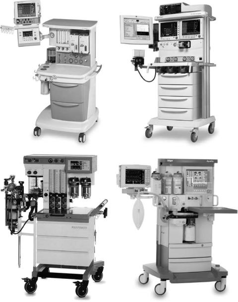
Figure 2. Four contemporary anesthesia workstations. The top two are manufactured by GE Healthcare, and the bottom two by Draeger Medical.
These goals will be discussed further in the following section, which describes the major components of the anesthesia delivery system. The following overview of anesthesia delivery system function will refer to these goals.
The anesthesia delivery system consists of four components: a breathing circuit, an anesthesia machine, a waste gas scavenger system, and an anesthesia ventilator. The breathing circuit is the functional center of the system, since it is physically and functionally connected to each of the other components and to the patient’s airway (Fig. 3). There is a one-way flow of gas from the anesthesia machine into the breathing circuit, and from the breathing circuit into the scavenger system. There is a bidirectional flow of gas between the breathing circuit and the patient’s lungs, and between the breathing
circuit and the anesthesia ventilator or reservoir bag. The ventilator and the reservoir bag are functionally interchangeable units, which are used during different modes of ventilation (Goal 2). During spontaneous and manually assisted modes of ventilation, the elastic reservoir bag is used as a source of inspired gas and a low impedance reservoir for exhaled gas. The anesthesia ventilator is used during mechanically controlled ventilation to automatically inflate the lungs using prescribed parameters (Goal 3).
During inhalation, gas flows from the anesthesia ventilator or reservoir bag through the breathing circuit to the patient’s lungs. The patient’s bloodstream takes up a small portion of gas (e.g., oxygen and anesthetic agent) from the lungs and releases carbon dioxide (CO2) into the lungs.
ANESTHESIA MACHINES |
31 |
During exhalation, gas flows from the patient’s lungs through the breathing circuit back to the anesthesia ventilator or reservoir bag. This bulk flow of gas, between the patient and the ventilator or reservoir bag, constitutes the patient’s pulmonary ventilation; the volume of each breath is referred to as tidal volume, and the total volume exchanged during one minute is referred to as minute volume.
Over time, the patient absorbs oxygen and anesthetic agents from, and releases CO2 to, the gas in the breathing circuit. Without intervention, the gas within the breathing circuit would progressively decrease in total volume, oxygen concentration, and anesthetic concentration. The anesthesia provider, therefore, dispenses fresh gas into the breathing circuit, replacing the gas absorbed by the patient. Using the anesthesia machine, the anesthesia provider precisely controls both the flow rate and the concentration of various gases in the fresh gas (Goal 1). The anesthesia machine is capable of delivering a total fresh gas flow that far exceeds the volume of gas absorbed by the patient. When higher fresh gas flows are used (for example, to rapidly change the concentration of gases in the breathing circuit), the excess gas is vented into the scavenger system to be evacuated from the operating room (Goal 5).
To conserve the use of anesthetic gases (Goal 4), the anesthesia provider will use a fresh gas flow rate that is significantly lower than the patient’s minute volume. In this situation, the patient reinhales gas that they had previously exhaled into the breathing circuit (this is called rebreathing). Carbon dioxide absorbent contained within the breathing circuit prevents the patient from rebreathing CO2, which would be deleterious. All other gases (oxygen, nitrous oxide, nitrogen, and anesthetic vapors) can be rebreathed safely.
During the course of a typical anesthetic, the anesthesia provider will use a relatively high fresh gas flow at the beginning and end of the anesthetic when a rapid change in
Figure 3. Block diagram of anesthesia delivery system components. The arrows show the direction of gas flow between components.
anesthetic concentration is desired, and a lower fresh gas flow when little change in concentration is desired. The technique of closed circuit anesthesia refers to the process of adjusting the fresh gas flow to exactly match the amount of gas used by the patient so that no gas is vented to the scavenging system.
Because anesthesia delivery systems provide critical life support functions to unconscious patients, equipment malfunctions and user errors can have catastrophic consequences. In 1974, the American National Standards Institute published an anesthesia machine standard that specified minimum performance and safety requirements for anesthesia gas machines (Goals 6 and 7). That standard was a landmark one, in that it was the first systematic approach to standardize the safety requirements for a medical device. Similar standards have since been written for other medical equipment, and the anesthesia machine standards have been regularly updated.
Breathing Circuit (Semiclosed Circle System)
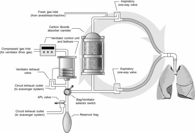
The semiclosed circle system is the most commonly used anesthesia breathing circuit, and the only type that will be discussed in this article. It is so named because expired gases can be returned to the patient in a circular fashion (Fig. 4). The components of the circle system include a carbon dioxide absorber canister, two one-way valves, a reservoir bag, an adjustable pressure-limiting valve, and tubes that connect to the patient, ventilator, anesthesia machine, and scavenger system.
During inspiration, the peak flow of gas exceeds 25 L min 1, far in excess of the rate of fresh gas supply. As a result, the patient will inspire both fresh gas and gas stored in the reservoir bag or ventilator bellows. Inspired gas travels through the carbon dioxide absorber canister, past the one-way inspiratory valve, to the patient. During
32 ANESTHESIA MACHINES
Figure 4. This schematic of the circle breathing circuit shows the circular arrangement of components. The one-way valves permit flow in only one direction.
exhalation, gas travels from the patient, past the one-way expiratory valve, to the reservoir bag (or ventilator bellows, depending upon the position of the bag–ventilator selector switch). The one-way valves establish the direction of gas flow in the breathing circuit. Carbon dioxide is not rebreathed because exhaled gas is directed through the carbon dioxide absorber canister prior to being reinhaled. Fresh gas from the anesthesia machine flows continuously into the breathing circuit. During inhalation, this gas joins with the inspiratory flow and is directed toward the patient. During exhalation, the fresh gas enters the breathing circuit and travels retrograde through the carbon dioxide absorber canister toward the reservoir bag (it does not travel toward the patient because the inspiratory oneway valve is closed during exhalation). Thus, during exhalation, gas enters the reservoir bag from the expiratory limb and from the carbon dioxide absorber canister. Once the reservoir bag is full, excess returning gas is vented out the adjustable pressure-limiting (APL) valve to the scavenger system (when the ventilator is used, the excess gas is vented out the ventilator exhaust valve). The total fresh gas flow will therefore control the amount of gas that is rebreathed. At high fresh gas flows, the exhaled gases are washed out through the scavenging system between each inspiration. At low fresh gas flow, very little exhaled gas is
forced out to the scavenging system and most of the exhaled gas is reinhaled in subsequent breaths.
CIRCLE SYSTEM COMPONENTS
CO2 Absorbents
Alkaline hydroxides of sodium, potassium, calcium, and barium in varying concentrations are most commonly used as carbon dioxide absorbents. These alkaline hydroxides irreversibly react with carbon dioxide to eventually form carbonates, releasing water and heat. Absorbent granules are 4- to 8-mesh in size (25–35 granules cm 3) to maximize the surface area available for chemical reaction and minimize the resistance to gas flow through the absorber canister. Ethyl violet is incorporated into the granules as a pH indicator; fresh granules are white, while a purple color indicates that the absorbent needs to be replaced. Absorber canisters are constructed with transparent sides so that absorbent color can be easily monitored during use. Canisters have a typical capacity of 900–1200 cm3 and the absorbent is good for 10–30 h of use, depending on the operating conditions.
Many of the absorbent materials have the potential to interact with anesthetic agents to degrade the anesthetics
and produce small amounts of potentially toxic gases, such as carbon monoxide. This is especially true if the absorbents are allowed to dessicate by exposure to high flows of dry gas (e.g., leaving the fresh gas flowing on the anesthesia machine over a weekend). Periodic replacement of absorbent, especially at the end of a weekend is therefore desirable. Newer absorbent materials, which are more costly, are designed to reduce or eliminate the potential for producing toxic gases by eliminating the hydroxides of sodium, barium, and potassium.
Unidirectional Valves
The inspiratory and expiratory one-way valves are simple, passive devices. Each has an inlet tube that is capped by a valve disk. When the pressure in the inlet tube exceeds that in the outlet tube, the valve opens to allow gas to flow downstream. The valve disks are light in weight to minimize gas flow resistance. Each valve has a clear dome to allow visual monitoring of valve function. Rarely, valves malfunction by failing to open or close properly. Carbon dioxide rebreathing can occur if either valve becomes incompetent (i.e., fails to close properly). This can occur if a valve disk becomes warped, sticks open due to humidity, or fails to seat properly.
Reservoir Bag
The reservoir bag is an elastic bag that serves three functions in the breathing circuit. First, it is a compliant element of an otherwise rigid breathing circuit that allows changes in breathing circuit gas volume without changes in breathing circuit pressure. Second, it provides a means for manually pressurizing the circuit to control or assist ventilation. Third, it provides a safety limit on the peak pressure that can be achieved in the breathing circuit. It acts as a pres- sure-limiting device in the event that fresh gas inflow exceeds APL valve outflow. Reservoir bags are designed such that, at fresh gas flow rates below 15 L min 1, the breathing circuit pressure will remain < 35 cm H2O (3.4 kPa) until the bag reaches more than twice its full capacity. Yet, inspiratory pressures up to 70 cm H2O (6.9 kPa) can be achieved by quickly compressing the reservoir bag.
APL Valve
The APL valve (euphemistically referred to as the pop-off valve) is a spring-loaded device that controls the flow of gas from the breathing circuit to the scavenger system. The valve opens when the pressure gradient from the circuit to the scavenger exceeds the force exerted by the spring (as discussed later, the pressure in the scavenger system is regulated to be equal to atmospheric pressure plus or minus a few cm H2O). When the patient is breathing spontaneously, the anesthesia practitioner minimizes the spring tension allowing the valve to open with minimal end-expiratory pressure (typically < 3 cm H2O, or 0.3 kPa). When the anesthesia practitioner squeezes the reservoir bag to manually control or assist ventilation, the APL valve opens during inhalation. Part of the gas exiting the reservoir bag escapes to the scavenger system and the remainder is directed toward the patient. By turning a knob, the
ANESTHESIA MACHINES |
33 |
anesthesia practitioner increases the pressure on the spring so that the APL valve remains closed until the pressure in the circuit achieves a level that is adequate to inflate the patients lungs; the APL valve thus opens toward the end of inhalation, once the lungs are adequately inflated. Continual adjustment of the APL valve is sometimes needed to adapt to changing fresh gas flow rate, circuit leaks, pulmonary mechanics, and ventilation parameters.
Bag–Ventilator Selector Switch
During mechanical ventilation, the reservoir bag and APL valve are disconnected from the breathing circuit and an anesthesia ventilator is connected to the same spot. Modern breathing circuits have a selector switch that quickly toggles the connection to either the ventilator or the reservoir bag and APL valve.
VIRTUES AND LIMITATIONS OF THE CIRCLE BREATHING CIRCUIT
Primary advantages of the circle breathing system over other breathing circuits include conservation of anesthetic gases and vapors, ease of use, and humidification and heating of inspired gases.
As stated previously, anesthetic agents are conserved when very low fresh gas flows are used with the circle breathing system. The minimum adequate flow is one that just replaces the gases taken up by the patient; for a normal adult, flows below 0.5 L min 1 can be achieved during anesthesia maintenance. It is customary to use higher fresh gas flow rates in the range of 1–2 L min 1, but this is still well below typical minute ventilation rates of 5–10 L min 1 which is the fresh gas flow that would be required for a nonrebreathing ventilation system.
The circle breathing circuit is easy to use because the same fresh gas settings can be used with patients of various sizes. A 100 kg adult and a 1 kg infant can each be anesthetized with a circle breathing system and a fresh gas maintenance flow rate of 1–2 L min 1. Since the larger patient would take up more anesthetic agent and more oxygen, and would give off more carbon dioxide, higher minimal flows would be required for the larger patient and the carbon dioxide absorbent would become exhausted quicker. Also, for convenience, a smaller reservoir bag and smaller bore breathing tubes would be selected for the smaller patient. But, otherwise, the system would function similarly for both patients.
Humidification and warming of inspired gases is another advantage of rebreathing. Fresh gas is mixed from compressed gases that contain zero water vapor, and breathing this dry gas can have detrimental effects on lung function. But, within the circle breathing system, inspired gas is humidified by the admixture of rebreathed gas, and by the water vapor that forms as a byproduct of carbon dioxide absorption. Both of these mechanisms also act to warm the inspired gas. By using low flows, enough heat and humidity is conserved to eliminate the need to actively heat and humidify inspired gas.
Most disadvantages of the circle breathing system are due to the large circuit volume. Internal volumes are primarily
34 ANESTHESIA MACHINES
Figure 5. Schematic showing the internal piping and placement of components within the anesthesia machine. Dark gray indicates oxygen (O2) and light gray indicates nitrous oxide (N2O).
determined by the sizes of the absorbent canister, reservoir bag, and breathing hoses; 3–6 L are typical. Large circuits are physically bulky. They also increase the time required to change inspired gas concentrations because the large reservoir of previously exhaled gas is continually added to fresh gas. Finally, large circuits are more compliant, which degrades the efficiency and accuracy of ventilation. This effect will be discussed further in the section on ventilators.
Anesthesia Machine
The anesthesia machine is used to accurately deliver into the breathing circuit a precise flow and concentration of gases and vapors. Anesthesia machines are manufactured to deliver various compressed gases; all deliver oxygen, most deliver nitrous oxide or air, some deliver helium or carbon dioxide. They have one or more vaporizers that convert liquid anesthetic agents into anesthetic vapors; currently used inhaled vapors include halothane, enflurane, isoflurane, sevoflurane, and desflurane. Anesthesia machines include numerous safety features that alert the anesthesia provider to malfunctions and avert use errors.
The anesthesia machine is a precision gas mixer (Fig. 5). Compressed gases enter the machine from the hospital’s centralized pipeline supply or from compressed gas cylinders. The compressed gases are regulated to specified pressures, and each passes through its own flow controller and flow meter assembly. The compressed gases then are mixed together and may flow through a single vaporizer where anesthetic vapor is added. The final gas mixture then exits the common gas outlet (also called the fresh gas outlet) to enter the breathing circuit.
ANESTHESIA MACHINE COMPONENTS
Compressed Gas Inlets
Compressed gases from the hospital pipeline system or from large compressed gas cylinders enter the anesthesia machine through flexible hoses. The inlet connector for each gas is unique in shape to prevent the connection of the wrong supply hose to a given inlet. The standardized design of each hose-inlet connector pair conforms to the Diameter Indexed Safety System (DISS)
(9).
Anesthesia machines also have inlet yokes that hold small compressed gas cylinders; these cylinders provide compressed gas for emergency backup and for use in locations without piped gases. Each yoke is designed to prevent incorrect placement of a cylinder containing another gas. Two pins located in the yoke must insert into corresponding holes on the cylinder valve stem. The standardized placement of these pins and corresponding holes, referred to as the Pin Indexed Safety System (PISS), is unique for each gas (10).
Pressure Regulators And Gauges
Gauges on the front panel of the anesthesia machine display the cylinder and pipeline inlet pressures of each gas. Gases from the pipeline inlets enter the anesthesia machine at pressures of 45–55 psig (310–380 kPa), whereas gases from the compressed gas cylinders enter at pressures up to 2000 psig (1379 kPa). (Pressure conversion factors: 1 psig ¼ 0.068 atm ¼ 51.7 mmHg ¼ 70.3 cm H2O ¼ 6.89 kPa.) Pressure regulators on each cylinder gas inlet line reduce the pressure from each cylinder to 45 psig (310 kPa). The pressure regulators provide a relatively constant outlet pressure in the presence of a variable inlet pressure, which is important since the pressure within a gas cylinder declines during use. Lines from the pipeline inlet and the cylinder inlet (downstream of the pressure regulator) join to form a common source line for each gas. Gases are preferentially used from the pipelines, since the pressure regulators are set to outlet pressures that are less than the usual pipeline pressures.
Flow Controllers And Meters
A separate needle-valve controls the flow rate of each compressed gas. Turning a knob on the front panel of the anesthesia machine counterclockwise opens the needle valve and increases the flow; turning it clockwise decreases or stops the flow. A flowmeter assembly, located above each flow-control knob, shows the resulting flow rate. The flowmeter consists of a tapered glass tube containing a movable float; the internal diameter of the tube is larger at the top than at the bottom. Gas flows up through the tube, which is vertically aligned, and in doing so blows the float higher in the tube. The float balances in midair partway up the tube when its weight equals the force of the gas traveling through the space between the float and the tube. Thus, the height to which the float rises within the tube is proportional to the flow rate of the gas. Flow rate is indicated by calibrated markings on the tube alongside the level of the float.
Each flowmeter assembly is calibrated for a specific gas. The density and viscosity of the gas significantly affects the force generated in traveling through the variable-sized annular orifice created by the outer edge of the float and the inner surface of the tube. Temperature and barometric pressure affect gas density, and major changes in either can alter flowmeter accuracy. Accuracy is also impaired by dirt or grease within the tube, static electricity between the float and the tube, and nonvertical alignment of the tube.
ANESTHESIA MACHINES |
35 |
To increase precision and accuracy, some machines indicate gas flow rate past a single needle valve using two flowmeter assemblies, one for high flows and the other for low flows. These flowmeters are connected in series and the flow rate is indicated on one flowmeter or the other. A flow rate below the range of the high-flow meter shows an accurate flow rate on the low flow meter and an unreadable low flow rate on the high flow meter. While, a flow rate that exceeds the range of the low-flow meter shows an accurate flow rate on the high flow meter and an unreadable high flow rate on the low flow meter.
Each gas, having passed through its individual flow controller and meter assembly, passes into a common manifold before continuing on. Only the individual gas flow rates are indicated on the flowmeters; the user must calculate the total gas flow rate and the percent concentration of each gas in the mixture.
Vaporizers
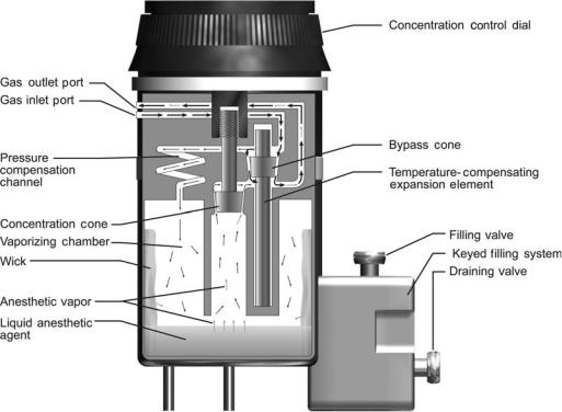
Vaporizers are designed to add an accurate amount of volatilized anesthetic to the compressed gas mixture. Anesthetic vapors are pharmacologically potent, so low concentrations (generally < 5%) are typically needed. The volatilized gases contribute to the total gas flow rate and dilute the concentration of the other compressed gases. The user can calculate these effects since they are not displayed on the machine front panel; luckily, these are generally negligible and can be ignored. Even though most anesthesia machines have multiple vaporizers, only one is used at a time; interlock mechanisms prevent a vaporizer from being turned on when another vaporizer is in use. Vaporizers are anesthetic agent specific and keyed filling systems prevent filling a vaporizer with the wrong liquid anesthetic.
All current anesthesia machines have direct-setting vaporizers that add a specified concentration of a single anesthetic vapor to the compressed gas mixture. Variablebypass vaporizers are the most common (Fig. 6). In these, the inflowing compressed gas mixture is split into two streams. One stream is directed through a bypass channel and the other is directed into a chamber within the vaporizer that contains liquid anesthetic agent. The gas entering the vaporizing chamber becomes saturated with anesthetic vapor at a concentration that depends on the vapor pressure of the particular liquid anesthetic. For example, sevoflurane has a vapor pressure of 157 mmHg (20.9 kPa) at 20 8C, so the gas within the vaporizing chamber is about 20% sevoflurane (at sea level). This highly concentrated anesthetic mixture exits the chamber (now, at a flow rate greater than that entering the chamber, due to the addition of anesthetic vapor) to join, and be diluted by, gas that traversed the bypass channel. A dial on the vaporizer controls the delivered anesthetic concentration by regulating the resistance to flow along each path. For example, setting a sevoflurane vaporizer to a dialed concentration of 1% splits the inflowing compressed gas mixture so that one-twenty-fourth of the total is directed through the vaporizing chamber and the remainder is directed through the bypass. Direct-reading variable-bypass vaporizers are calibrated for a specific agent, since each anesthetic liquid has a different vapor pressure. Vapor pressure varies with
36 ANESTHESIA MACHINES
Figure 6. Schematic of a variable-bypass vaporizer. Arrows indicate direction of gas flow; heavier arrows indicate larger flow rates. Gas enters the Inlet Port and is split at the Bypass Cone into two streams. One stream is directed through a bypass channel and the rest enters the Vaporizing Chamber. Gas entering the Vaporizing Chamber equilibrates with Liquid Anesthetic Agent to become saturated with Anesthetic Vapor. This concentrated anesthetic mixture exits the chamber to join, and be diluted by, gas that traversed the bypass channel. The Concentration Control Dial is attached to the Concentration Cone, which regulates resistance to flow exiting the Vaporizing Chamber and thus controls the anesthetic concentration dispensed from the Outlet Port.
temperature, so vaporizers are temperature compensated; at higher temperatures, a temperature sensitive valve diverts more gas through the bypass channel. Vaporizers are designed to ensure that the gas within the liquid-containing chamber is saturated with anesthetic vapor. A cotton wick within the chamber promotes saturation by increasing the surface area of the liquid. Thermal energy is required for liquid vaporization (heat of vaporization). To minimize cooling of the anesthetic liquid, vaporizers are constructed of metals with high specific heat and high thermal conductivity so that heat is transferred easily from the surroundings. The output of variable-bypass vaporizers varies with barometric pressure; delivered concentration increases as barometric pressure decreases.
Desflurane vaporizers are designed differently because desflurane has such a high vapor pressure (664 mmHg, or 88.5 kPa, at 20 8C) and low boiling point (22.8 8C). Uncontrollably high output concentrations could easily occur if desflurane were administered at room temperature from a variable-bypass vaporizer. In a desflurane vaporizer, the liquid desflurane is electrically heated to a controlled temperature of 39 8C within a pressure-tight chamber. At this temperature, the vapor pressure of desflurane is 1500 mmHg (200 kPa) and the anesthetic vapor above the liquid is a compressed gas. The concentration dial on the vaporizer regulates a computer-assisted flow proportioning mechan-
ism that meters pressurized desflurane into the incoming gas mixture to achieve a set output concentration of desflurane vapor. Room temperature does not affect the output concentration of the vaporizer, nor does barometric pressure. The vaporizer requires electrical power for the heater, the onboard computer, and two electronic valves.
Safety Systems
By written standard, the anesthesia machine has numerous safety systems designed to prevent use errors. Some of these, such as the DISS and PISS systems to prevent compressed gas misconnections, interlock mechanisms to prevent simultaneous use of multiple vaporizers, and keyed filler systems to prevent misfilling of vaporizers, have already been discussed. Others are presented, below.
Failsafe Mechanism And Oxygen Alarm. The anesthesia machine has a couple of safety systems that alert the user and stop the flow of other gases when the oxygen supply runs out (for example, when an oxygen tank becomes depleted). An auditory alarm sounds and a visual message appears to alert the user when the oxygen supply pressure falls below a predetermined threshold pressure of 30 psig (207 kPa). A failsafe valve in the gas line supplying each flow controller-meter assembly, except oxygen, stops the
flow of other gases. The failsafe valve is either an on–off valve or a pressure-reducing valve that is controlled by the pressure within the oxygen line. When the oxygen supply pressure falls below the threshold level, the failsafe valves close to stop the flow, or proportionally reduce the supply pressure, of all the other gases. This prevents administration of hypoxic gases (e.g., nitrous oxide, helium, nitrogen, carbon dioxide) without oxygen, which could rapidly cause injury to the patient, but it also prevents administration of air without oxygen. The failsafe mechanisms do not prevent delivery of hypoxic gas mixtures in the presence of adequate oxygen supply pressure; the gas proportioning system, described below, prevents this.
Gas Proportioning System. Anesthesia machines are equipped with proportioning systems that prevent the delivery of high concentrations of nitrous oxide, the most commonly used non-oxygen containing gas. A mechanical or pneumatic link between the oxygen and nitrous oxide lines ensures that nitrous oxide does not flow without an adequate flow of oxygen. One such mechanism, the DatexOhmeda Link-25 system, is a chain linkage between sprockets on the nitrous oxide and oxygen flow needle valves. The linkage is engaged whenever the nitrous oxide is set to exceed three-times the oxygen flow, or when the oxygen flow is set to less than one-third of the nitrous oxide flow; this limits the nitrous oxide concentration to a maximum of 75% in oxygen. Another mechanism, the Draeger Oxygen Ratio Monitor Controller (ORMC), is a slave flow control valve on the nitrous oxide line that is pneumatically linked to the oxygen line. This system limits the flow of nitrous oxide to a maximum concentration of 72 3% in oxygen. Both of the above systems control the ratios of nitrous oxide and oxygen, but do not compensate for other gases in the final mixture; a hypoxic mixture (oxygen concentration < 21%) could be dispensed, therefore, if a third gas were added in significant concentrations.
Oxygen Flush. Each anesthesia machine has an oxygen flush system that can rapidly deliver 45–70 L min 1 of oxygen to the common gas outlet. The user presses the oxygen flush valve in situations where high flow oxygen is needed to flush anesthetic agents out of the breathing circuit, rapidly increase the inhaled oxygen concentration, or compensate for a large breathing circuit leak (for example, during positive pressure ventilation of the patient with a poorly fitted face mask). The oxygen flush system also serves as a safety system because it bypasses most of the internal plumbing of the anesthesia machine (e.g., safety control valves, flow controller-meter assemblies, and vaporizers) and because it is always operational, even when the anesthesia machine’s master power switch is off.
Monitors and User-Interface Features. Written standards specify that all anesthesia machines must be equipped with essential safety monitors and user-interface features. To protect against hypoxia, each has an integrated oxygen analyzer that monitors the oxygen concentration in the breathing circuit whenever the anesthesia machine is powered on. The oxygen monitor must have an
ANESTHESIA MACHINES |
37 |
audible alarm that sounds whenever the oxygen concentration falls below a preset threshold, which cannot be set < 18%. To protect against dangerously high and low airway pressures, the breathing circuit pressure is continuously monitored by an integrated system that alarms in the event of sub-atmospheric airway pressure, sustained high airway pressure, or extremely high airway pressure. To protect against ventilator failure and breathing circuit disconnections, the breathing circuit pressure is monitored to ensure that adequate positive pressure is generated at least a few times a minute whenever the ventilator is powered on; a low airway pressure alarm (AKA disconnect alarm) is activated whenever the breathing circuit pressure does not reach a user-set threshold level over a 15 s interval. User-interface features protect against mistakes in gas flow settings. Oxygen controls are always positioned to the right of other gas flow controls. The oxygen flow control knob has a unique size and shape that is different from the other gas control knobs. The flow control knobs are protected against their being bumped to prevent accidental changes in gas flow rates. All gas flow knobs and vaporizer controls uniformly increase their settings when turned in a clockwise direction.
LIMITATIONS
Anesthesia machines are generally reliable and problemfree. Limitations include that they require a source of compressed gases, are heavy and bulky, are calibrated to be accurate at sea level, and are designed to function in an upright position within a gravitational field. Machine malfunctions are usually a result of misconnections or disconnections of internal components during servicing or transportation. Aside from interlock mechanisms that decrease the likelihood of wrong gas or wrong anesthetic agent problems, there are no integrated monitors to ensure that the vaporizers are filled with the correct agents and the flow meters are dispensing the correct gases. Likewise, except for oxygen, the gas supply pressures and anesthetic agent levels are not automatically monitored. Thus, problems can still result when the anesthesia provider fails to diagnose a problem with the compressed gas or liquid anesthetic supplies.
Ventilator
General anesthesia impairs breathing by two mechanisms, it decreases the impetus to breath (central respiratory depression), and it leads to upper airway obstruction. Additionally, neuromuscular blockers, which are often administered during general anesthesia, paralyze the muscles of respiration. For these reasons, breathing may be supported or controlled during anesthesia to ensure adequate minute ventilation. The anesthesia provider can create intermittent positive pressure in the breathing circuit by rhythmically squeezing the reservoir bag. Ventilatory support is often provided in this way for short periods of time, especially during the induction of anesthesia. During mechanical ventilation, a selector switch is toggled to disconnect the reservoir bag and APL valve from the breathing circuit and connect an anesthesia ventilator instead. Anesthesia
38 ANESTHESIA MACHINES
ventilators provide a means to mechanically control ventilation, delivering consistent respiratory support for extended periods of time and freeing the anesthesia provider’s hands and attention for other tasks. Most surgical patients have normal pulmonary mechanics and can be adequately ventilated with an unsophisticated ventilator designed for ease of use. But, high performance anesthesia ventilators allow safe and effective ventilation of a wide variety of patients, including neonates and the critically ill.
Most anesthesia ventilators are pneumatically powered, electronically controlled, and time cycled. All can be set to deliver a constant tidal volume at a constant rate (volume control). Many can also be set to deliver a constant inspiratory pressure at a constant rate (pressure control). All anesthesia ventilators allow spontaneous patient breaths between ventilator breaths (intermittent mandatory ventilation, IMV), and all can provide PEEP during positive pressure ventilation (note that in some older systems PEEP is set using a PEEP-valve integrated into the expiratory limb of the breathing circuit, and is not actively controlled by the ventilator). In general, anesthesia ventilators do not sense patient effort, and thus do not provide synchronized modes of ventilation, pressure support, or continuous positive airway pressure (CPAP).
As explained above, the anesthesia delivery system conserves anesthetic gases by having the patient rebreathe previously exhaled gas. Unlike intensive care ventilators, which deliver new gas to the patient during every breath, anesthesia ventilators function as a component of the anesthesia delivery system and maintain rebreathing during mechanical ventilation. In most anesthesia ventilators, this is achieved by incorporating a bellows assembly (see Fig. 4). The bellows assembly consists of a distensible bellows that is housed in a clear rigid chamber. The bellows is functionally equivalent to the reservoir bag; it is attached to, and filled with gas from, the breathing circuit. During inspiration, the ventilator injects drive gas into the rigid chamber; this squeezes the bellows and directs gas from the bellows to the patient via the inspiratory limb of the breathing circuit. The drive gas, usually oxygen or air, remains outside of the bellows and never enters the breathing circuit. During exhalation, the drive gas within the rigid chamber is vented to the atmosphere, and the patient exhales into the bellows through the expiratory limb of the breathing circuit.
The bellows assembly also contains an exhaust valve that vents gas from the breathing circuit to the scavenger system. This ventilator exhaust valve serves the same function during mechanical ventilation that the APL valve serves during manual or spontaneous ventilation. However, unlike the APL valve, it is held closed during inspiration to ensure that the set tidal volume dispensed from the ventilator bellows is delivered to the patient. Excess gas then escapes from the breathing circuit through this valve during exhalation.
The tidal volume set on an anesthesia ventilator is not accurately delivered to the patient; it is augmented by fresh gas flow from the anesthesia machine, and reduced due to compression-loss within the breathing circuit. Fresh gas, flowing into the breathing circuit from the anesthesia machine, augments the tidal volume delivered from the
ventilator because the ventilator exhaust valve, which is the only route for gas to escape from the breathing circuit, is held closed during inspiration. For example, at a fresh gas flow rate of 3 L min 1 (50 mL s 1), and ventilator settings of 10 breaths min 1 and an I/E ratio of 1:2 (inspiratory time ¼ 2 s), the delivered tidal volume is augmented by 100 mL per breath (2 s per breath 50 mL s 1). Conversely, the delivered tidal volume is reduced due to compression loss within the breathing circuit. The magnitude of this loss depends on the compliance of the breathing circuit and the peak airway pressure. Circle breathing circuits typically have a compliance of 7–9 mL cm 1 H2O (70–90 mL kPa 1), which is significantly higher than the typical 1–3 mL cm 1 H2O (10–30 mL kPa 1) circuit compliance of intensive care ventilators, because of their large internal volume. For example, when ventilating a patient with a peak airway pressure of 20 cm H2O (2 kPa) using an anesthesia ventilator with a breathing circuit compliance of 10 mL cm H2O, delivered tidal volume is reduced by 200 mL per breath.
LIMITATIONS
Until recently, anesthesia ventilators were simple devices designed to deliver breathing circuit gas in volume control mode. The few controls consisted of a power switch, and dials to set respiratory rate, inspiratory/expiratory (I/E) ratio, and tidal volume. While simple to operate, these ventilators had a number of limitations. As discussed above, delivered tidal volume was altered by peak airway pressure and fresh gas flow rate. Tidal volume augmentation was particularly hazardous with small patients, such as premature infants and neonates, since increasing the gas flow on the anesthesia machine could unintentionally generate dangerously high tidal volumes and airway pressures. Tidal volume reduction was particularly hazardous since dramatically lower than set tidal volumes could be delivered, unbeknown to the provider, to patients requiring high ventilating pressures (e.g., those with severe airway disease or respiratory distress syndrome). Worse yet, the pneumatic drive capabilities of these ventilators were sometimes insufficient to compensate for tidal volume losses due to compression within the breathing circuit; anesthesia ventilators were unable to adequately ventilate patients with high airway pressures (> 45 cm H2O) requiring large minute volumes (> 10 L min 1). Another imperfection of anesthesia ventilators is that they are pneumatically powered by compressed gases. The ventilator’s rate of compressed gas consumption, which is approximately equal to the set minute volume (5–10 L min 1 in a normal size adult), is not a concern when central compressed gas supplies are being used. But the ventilator can rapidly deplete oxygen supplies when compressed gas is being dispensed from the emergency backup cylinders attached to the anesthesia machine (e.g., a backup cylinder could provide over 10 h of oxygen to a breathing circuit at low flow, but would last only one-hour if also powering the ventilator). Lastly, anesthesia ventilators that do not sense patient effort are unable to provide synchronized or supportive modes of ventilation. This limitation is most significant during spontaneous ventilation, since CPAP and pressure support cannot be provided to compensate
for the additional work of breathing imposed by the breathing circuit and endotracheal tube, or to prevent the low lung volumes and atalectasis that result from general anesthesia. New anesthesia ventilators, introduced in the past 10 years, address many of these limitations as discussed later in the section on New Technologies.
Scavenger System
Waste anesthetic gases are vented from the operating room to prevent potentially adverse effects on health care workers. High volatile anesthetic concentrations in the operating room atmosphere can cause problems such as headaches, dysphoria, and impaired psychomotor functioning; chronic exposure to trace levels has been implicated as a causative factor for cancer, spontaneous abortions, neurologic disease, and genetic malformations, although many studies have not borne out these effects. The National Institute for Occupational Safety and Health (NIOSH) recommends that operating room levels of halogenated anesthetics be < 2 parts per million (ppm) and that nitrous oxide levels be < 25 ppm. Waste gases can be evacuated from the room actively via a central vacuum system, or passively via a hose to the outside; alternatively, the waste gas can pass through a canister containing activated charcoal, which absorbs halogenated anesthetics.
The scavenger system is the interface between the evacuation systems described in the preceding sentence and the exhaust valves on the breathing circuit and ventilator (i.e., APL valve and ventilator exhaust valve). It functions as a reservoir that holds waste gas until it can vent to the evacuation system. This is necessary because gas exits the exhaust valves at a non-constant rate that may, at times, exceed the flow rate of the evacuation system. The scavenger system also ensures that the downstream pressure on the exhaust valves does not become too high or too negative. Excessive pressure at the exhaust valve outlet could cause sustained high airway pressure leading to barotrauma and cardiovascular collapse; whereas, excessive vacuum at the exhaust valve outlet could cause sustained negative airway pressure leading to apnea and pulmonary edema.
There are two categories of scavenger systems, open and closed. Open scavenger systems can only be used with a vacuum evacuation system. In an open scavenger system, waste gas enters the bottom of a rigid reservoir that is open to the atmosphere at the top, and gas is constantly evacuated from the bottom of the reservoir into the vacuum. Room air is entrained into the reservoir whenever the vacuum flow rate exceeds the waste gas flow rate, and gas spills out to the room through the openings in the reservoir whenever the waste gas flow rate exceeds the vacuum flow rate. The arrangement of the components prevents spillage of waste gas out of the reservoir openings unless the average vacuum flow rate is less than the average flow out of the exhaust valves.
Closed scavenger systems consist of a compliant reservoir bag with an inflow of waste gas from the exhaust valves of the breathing system and an outflow to the active or passive evacuation system. Two or more valves regulate the internal pressure of the closed scavenger system. A
ANESTHESIA MACHINES |
39 |
negative pressure release valve opens to allow entry of room air whenever the pressure within the system becomes too negative, < 1.8 cm H2O ( 0.18 kPa) (i.e., in situations where the evacuation flow exceeds the exhaust flow and the reservoir bag is collapsed). A positive pressure release valve opens to allow venting of waste gas to the room whenever the pressure within the scavenger system becomes too high, > 5 cm H2O (0.5 kPa) (i.e., in situations where the reservoir bag is full and the exhaust flow exceeds the evacuation flow). Thus, the pressure within the scavenger system is maintained between 1.8 and 5.0 cm H2O.
Integrated Monitors
All anesthesia delivery systems have integrated electronic safety monitors intended to avert patient injuries. Included are (1) an oxygen analyzer, (2) an airway pressure monitor, and (3) a spirometer.
The oxygen analyzer measures oxygen concentration in the inspiratory limb of the breathing circuit to guard against the administration of dangerously low inhaled oxygen concentrations. Most analyzers use a polarographic or galvanic (fuel cell) probe that senses the rate of an oxygen-dependent electrochemical reaction. These analyzers are inexpensive and reliable, but are slow to equilibrate to changes in oxygen concentration (response times on the order of 30 s). They also require daily calibration. Standards stipulate that the oxygen analyzer be equipped with an alarm, and be powered-on whenever the anesthesia delivery system is in use.
The airway pressure monitor measures pressure within the breathing circuit, and warns of excessively high or negative pressures. It also guards against apnea during mechanical ventilation. Most anesthesia delivery systems have two pressure gauges: an analog Bourdon tube pressure gauge that displays instantaneous pressure on a mechanical dial, and an electronic strain-gauge monitor that displays a pressure waveform. Most electronic pressure monitors embody an alarm system with variable-threshold negative pressure, positive pressure, and sustained pressure alarms that can be adjusted by the user. An apnea alarm feature, which is enabled whenever the ventilator is powered-on, ensures that positive pressure is sensed within the breathing circuit at regular intervals. On some anesthesia delivery systems pressure is sensed within the circle system absorber canister; on other systems it is sensed on the patient side of the one-way valves; the latter gives a more accurate reflection of airway pressure.
The spirometer measures gas flow in the expiratory limb of the breathing circuit and guards against apnea and dangerously low or high respiratory volumes. A number of different techniques are commonly used to measure flow. These include spinning vanes, rotating sealed spirometers, ultrasonic, and variable orifice differential pressure. Respiratory rate, tidal volume, and minute volume are derived from the sensor signals and displayed to the user. Some machines also display a waveform of exhaled flow versus time. Most spirometers have an alarm system with variable-threshold alarms for low and high tidal volume, as well as an apnea alarm that is triggered if no flow is detected during a preset interval.
40 ANESTHESIA MACHINES
In addition to these standard monitors, some anesthesia workstations have integrated gas analyzers that measure inhaled and exhaled concentrations of oxygen, carbon dioxide, nitrous oxide, and volatile anesthetic agents. Although stand-alone gas analyzers are available, they are likely to be integrated into the anesthesia workstation because they monitor gas concentrations and respiratory parameters that are controlled by the anesthesia delivery system.
Other patient monitors, such as electrocardiography, pulse oximetry, invasive and noninvasive blood pressure, and thermometry may also be integrated into the anesthesia workstation; but often stand-alone monitors are placed on the shelves of the anesthesia delivery system. In either case, standard patient monitors must be used during the conduct of any anesthetic to evaluate the adequacy of the patient’s oxygenation, ventilation, circulation, and body temperature. Monitoring standards, which have contributed to the dramatic increase in anesthesia safety, were initially published by the American Society of Anesthesiologists in 1986 and have been continually evaluated and updated (8).
New Technologies
The anesthesia delivery system as described thus far has evolved incrementally from a pneumatic device designed in 1917, by Henry Boyle for administration of anesthesia using oxygen, nitrous oxide and ether. The evolution of Boyle’s machine has occurred in stages. In the 1950s and 1960s the failsafe devices and fluidic controlled ventilators were added. In the 1970s and early 1980s the focus was on improving safety with features, such as gas proportioning systems, safety alarms, electronically controlled ventilators, and standardization of the user interface to decrease errors. In the late 1980s and 1990s, monitors and electronic recordkeeping were integrated to create anesthesia workstations. Since 2000 the focus has been on improving ventilator performance, incorporating automated machine self-checks, and transitioning to electronically controlled and monitored flow meters and vaporizers. Some of the new technologies that have been introduced in the last few years are discussed, below.
BREATHING CIRCUIT
As discussed above, the tidal volume set on an anesthesia ventilator is not accurately delivered to the patient because of two breathing circuit effects. First, a portion of the volume delivered from the ventilator is compressed within the breathing circuit and does not reach the patient. Second, fresh gas flowing into the breathing circuit augments the delivered tidal volume. A number of techniques are used to minimize these effects in new anesthesia delivery systems.
Two techniques have been used to minimize the effect of gas compression. First, smaller, less compliant breathing circuits are being used. This has been achieved by minimizing the use of compliant hoses between the ventilator and breathing circuit and by decreasing the size of the absorber canister. A tradeoff is that the absorbent must be changed more frequently with a smaller canister, hence new breathing circuits are designed so that the carbon dioxide absorbent can be exchanged during use. Second, many new machines automatically measure breathing
circuit compliance during an automated preuse checkout procedure and then compensate for breathing circuit compliance during positive pressure ventilation; the ventilator continually senses airway pressure and delivers additional volume to make up for that lost to compression.
A number of techniques have also been used to eliminate augmentation of tidal volume by fresh gas flowing into the circuit. In one approach, the ventilator automatically adjusts its delivered volume to compensate for the influx of fresh gas into the breathing circuit. The ventilator either adjusts to maintain a set exhaled tidal volume as measured by a spirometer in the expiratory limb of the breathing circuit, or it responds to maintain a set inhaled tidal volume sensed in the inspiratory limb, or it modifies its delivered volume based on the total fresh gas flow as measured by electronic flowmeters in the anesthesia machine. None of the above methods requires redesign of the breathing circuit, except for the addition of flow sensors that communicate with the ventilator.
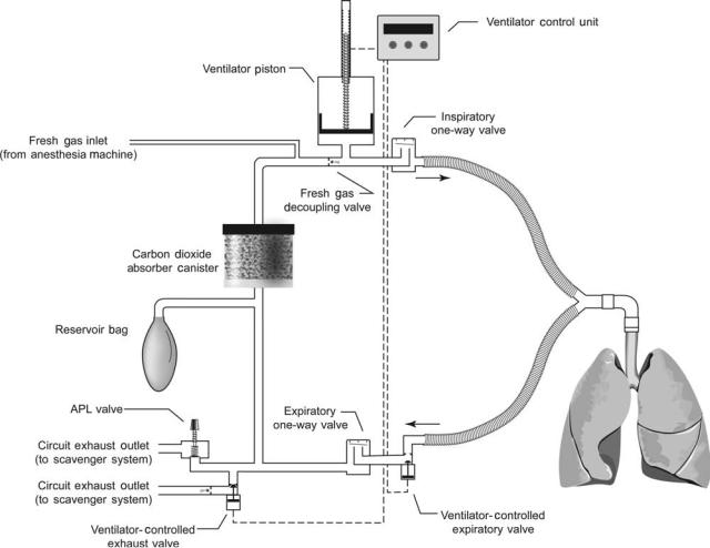
In a radically different approach, called fresh gas decoupling, the breathing circuit is redesigned so that fresh gas flow is channeled away from ventilator-delivered gas during inspiration, which removes the augmenting effect of fresh gas flow on tidal volume. An example of such a breathing circuit is illustrated in Fig. 7. In this circuit, during inhalation, gas dispensed from a piston driven ventilator travels directly to the patient’s lungs; retrograde flow is blocked by a passive fresh gas decoupling valve, and expiratory flow is blocked by the ventilator-controlled expiratory valve, which is actively closed during the inspiratory phase. Fresh gas does not contribute to the delivered tidal volume; instead it flows retrograde into a nonpressurized portion of the breathing circuit. During exhalation, the ventilatorcontrolled expiratory valve opens, and the ventilator piston withdraws to actively fill with a mixture of fresh gas and gas from the reservoir bag. This design causes a number of other functional changes. First, the breathing circuit compliance is lower during positive pressure ventilation, since only part of the breathing circuit is pressurized during inspiration (the volume between the fresh gas decoupling valve and the ventilator-controlled expiratory valve). Second, the reservoir bag remains in the circuit during mechanical ventilation. As a result, it fills and empties with gas throughout the ventilator cycle, which is an obvious contrast to the absence of bag movement during mechanical ventilation with a conventional circle breathing circuit.
ANESTHESIA MACHINE
Many new anesthesia machines have electronic gas flow sensors instead of tapered glass tubes with internal floats. Advantages include (1) improved reliability and reduced maintenance; (2) improved precision and accuracy at lowflows; and (3) ability to automatically record and use gas flows (for instance to adjust the ventilator). The electronic sensors operate on the principle of heat transfer, measuring the energy required to maintain the temperature of a heated element in the gas flow pathway. Each sensor is calibrated for a particular gas, since every gas has a different specific heat index. Gas flows are shown on dedicated light-emitting diode (LED) displays or on the
ANESTHESIA MACHINES |
41 |
Figure 7. Example of a breathing circuit with fresh gas decoupling. This breathing circuit is used in the Draeger Fabius anesthesia machine. It contains three passive one-way valves and two active valves that are controlled by the ventilator during mechanical ventilation.
main anesthesia machine flat panel display. Most anesthesia machines still regulate the flow of each gas using mechanical needle valves, but in some these have been replaced with electronically control valves. Electronically controlled valves provide a mechanism for computerized gas proportioning systems that limit the ratios of multiple gases. Some machines with electronic flow control valves allow the user to select the balance gas (i.e., air or nitrous oxide) and set a desired oxygen concentration and total flow, leaving the calculation of individual gas flow rates to the machine.
Most new anesthesia machines continue to use mechanical vaporizers as described above, but a few incorporate electronic vaporizers. These operate on one of two principles: either computer-controlled variable bypass, or computer-controlled liquid injection. Computerized variable bypass vaporizers control an electronic valve that regulates the flow of gas exiting from the liquid anesthetic containing chamber to join the bypass stream. The valve is adjusted to reach a target flow that is based upon the: (1) dial setting, (2) temperature in the vaporizing chamber, (3) total pressure in the vaporizing chamber, (4) bypass flow, and (5) liquid anesthetic identity. Computerized injectors
continuously add a measured amount liquid anesthetic directly into the mixed gas coming from the flowmeters based upon the: (1) dial setting, (2) mixed gas flow, and (3) liquid anesthetic identity. Electronic vaporizers offer a number of advantages. First, they provide a mechanism for vaporizer settings to be automatically recorded and controlled. Second, a number of different anesthetics can be dispensed (one at a time) using a single control unit, provided that the computer knows the identity of the anesthetic liquid.
VENTILATOR
Anesthesia ventilator technology has improved dramatically over the past 10 years and each new machine brings further advancements. As discussed above, most new ventilators compensate for the effects of circuit compliance and fresh gas flow, so that the set tidal volume is accurately delivered. Older style ventilators notoriously delivered low tidal volumes to patients requiring high airway pressures, but new ventilators overcome this problem with better flow generators, compliance compensation and feedback