
- •VOLUME 1
- •CONTRIBUTOR LIST
- •PREFACE
- •LIST OF ARTICLES
- •ABBREVIATIONS AND ACRONYMS
- •CONVERSION FACTORS AND UNIT SYMBOLS
- •ABLATION.
- •ABSORBABLE BIOMATERIALS.
- •ACRYLIC BONE CEMENT.
- •ACTINOTHERAPY.
- •ADOPTIVE IMMUNOTHERAPY.
- •AFFINITY CHROMATOGRAPHY.
- •ALLOYS, SHAPE MEMORY
- •AMBULATORY MONITORING
- •ANALYTICAL METHODS, AUTOMATED
- •ANALYZER, OXYGEN.
- •ANESTHESIA MACHINES
- •ANESTHESIA MONITORING.
- •ANESTHESIA, COMPUTERS IN
- •ANGER CAMERA
- •ANGIOPLASTY.
- •ANORECTAL MANOMETRY
- •ANTIBODIES, MONOCLONAL.
- •APNEA DETECTION.
- •ARRHYTHMIA, TREATMENT.
- •ARRHYTHMIA ANALYSIS, AUTOMATED
- •ARTERIAL TONOMETRY.
- •ARTIFICIAL BLOOD.
- •ARTIFICIAL HEART.
- •ARTIFICIAL HEART VALVE.
- •ARTIFICIAL HIP JOINTS.
- •ARTIFICIAL LARYNX.
- •ARTIFICIAL PANCREAS.
- •ARTERIES, ELASTIC PROPERTIES OF
- •ASSISTIVE DEVICES FOR THE DISABLED.
- •ATOMIC ABSORPTION SPECTROMETRY.
- •AUDIOMETRY
- •BACTERIAL DETECTION SYSTEMS.
- •BALLOON PUMP.
- •BANKED BLOOD.
- •BAROTRAUMA.
- •BARRIER CONTRACEPTIVE DEVICES.
- •BIOCERAMICS.
- •BIOCOMPATIBILITY OF MATERIALS
- •BIOELECTRODES
- •BIOFEEDBACK
- •BIOHEAT TRANSFER
- •BIOIMPEDANCE IN CARDIOVASCULAR MEDICINE
- •BIOINFORMATICS
- •BIOLOGIC THERAPY.
- •BIOMAGNETISM
- •BIOMATERIALS, ABSORBABLE
- •BIOMATERIALS: AN OVERVIEW
- •BIOMATERIALS: BIOCERAMICS
- •BIOMATERIALS: CARBON
- •BIOMATERIALS CORROSION AND WEAR OF
- •BIOMATERIALS FOR DENTISTRY
- •BIOMATERIALS, POLYMERS
- •BIOMATERIALS, SURFACE PROPERTIES OF
- •BIOMATERIALS, TESTING AND STRUCTURAL PROPERTIES OF
- •BIOMATERIALS: TISSUE-ENGINEERING AND SCAFFOLDS
- •BIOMECHANICS OF EXERCISE FITNESS
- •BIOMECHANICS OF JOINTS.
- •BIOMECHANICS OF SCOLIOSIS.
- •BIOMECHANICS OF SKIN.
- •BIOMECHANICS OF THE HUMAN SPINE.
- •BIOMECHANICS OF TOOTH AND JAW.
- •BIOMEDICAL ENGINEERING EDUCATION
- •BIOSURFACE ENGINEERING
- •BIOSENSORS.
- •BIOTELEMETRY
- •BIRTH CONTROL.
- •BLEEDING, GASTROINTESTINAL.
- •BLADDER DYSFUNCTION, NEUROSTIMULATION OF
- •BLIND AND VISUALLY IMPAIRED, ASSISTIVE TECHNOLOGY FOR
- •BLOOD BANKING.
- •BLOOD CELL COUNTERS.
- •BLOOD COLLECTION AND PROCESSING
- •BLOOD FLOW.
- •BLOOD GAS MEASUREMENTS
- •BLOOD PRESSURE MEASUREMENT
- •BLOOD PRESSURE, AUTOMATIC CONTROL OF
- •BLOOD RHEOLOGY
- •BLOOD, ARTIFICIAL
- •BONDING, ENAMEL.
- •BONE AND TEETH, PROPERTIES OF
- •BONE CEMENT, ACRYLIC
- •BONE DENSITY MEASUREMENT
- •BORON NEUTRON CAPTURE THERAPY
- •BRACHYTHERAPY, HIGH DOSAGE RATE
- •BRACHYTHERAPY, INTRAVASCULAR
- •BRAIN ELECTRICAL ACTIVITY.
- •BURN WOUND COVERINGS.
- •BYPASS, CORONARY.
- •BYPASS, CARDIOPULMONARY.
590 BRACHYTHERAPY, HIGH DOSAGE RATE
BRACHYTHERAPY, HIGH DOSAGE RATE
RUPAK DAS
University of Wisconsin
Madison, Wisconsin
INTRODUCTION
Brachytherapy is a form of radiotherapy whereby a radioactive source is used inside or at short distance from the tumor. There are three different forms of brachytherapy: interstitial, intracavitary, and skin therapy. In interstitial brachytherapy, the radioactive sources are implanted inside and throughout the tumor volume; in intracavitary brachytherapy the sources are placed in the body cavities very close to the tumor; while in skin therapy the sources are placed on the skin surface. Conventionally, brachytherapy implants have delivered the radiation at a low dose rate (dose rates of < 1 Gy h 1). Low dose-rate (LDR) interstitial implants can be temporary (meaning that the radioactive sources are left in place for a period of time, usually a few days, and then removed) or permanent (left in place without removal), while intracavitary implants are temporary. The advent of methods to deliver the dose at a much higher dose rates, in the range of 1–5 Gy min 1, brought an increase in the use of brachytherapy. All high dose-rate (HDR) brachytherapy treatments are temporary and treatments are administered using discrete fractions.
What Is a Remote Afterloader?
A remote afterloader (RAL) is a computer driven system that transports the radioactive source from a shielded safe into the applicator placed in the patient. Upon termination or interruption of the treatment, the source is driven back to its safe. The device may move the source by one of several methods, most commonly pneumatic air pressure or cable drives.
What is Stepping-Source Remote Afterloader?
A stepping source RAL is a particular design of the treatment unit that consists of a single source at the end of a cable that moves the source through applicators placed in the treated volume. The treatment unit can treat implants consisting of many needles or catheters in the patient. Multiple catheters are often required to cover the target with adequate radiation doses. Each catheter or part of an applicator is connected to the RAL through a channel. The computer drives the cable so that the source moves from the safe through a given channel to the programmed position in the applicator (dwell position) for a specific amount of time (dwell time). In any applicator, there may be many dwell positions. After treating all the positions in a given catheter (channel) the source is retracted to its safe and then driven to the next channel. The dwell positions and the dwell time in each channel are independently programmable, thereby giving a high level of flexibility of dose delivery. All currently available HDR RALs use the step- ping-source design.
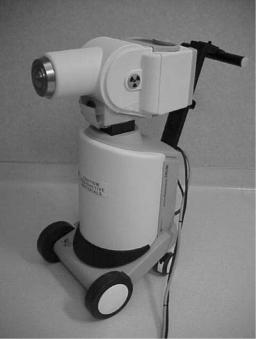
Currently there are three types of HDR RALs available in the market: MicroSelectron (Fig. 1, vendor Nucletron,
Veenendaal, Netherlands), Gamma-Med (Fig. 2), and VariSource (Fig. 3, both marketed by Varian Associates, Palo Alto, CA).
The specific features of the three different RALs are shown in Table 1.
COMPONENTS OF A HIGH DOSE RATE REMOTE AFTERLOADER
While different in detail, all available HDR RALs consist of the same general components. Figure 4 gives an overview of the systems, with the major parts described below.
Shielded Safe
To provide a dose rate in the range of 1–5 Gy min 1 in a RAL requires a 192Ir source of 4–10 Ci. A shielded safe, which is an integrated part of the treatment unit, provides enough radiation shielding to house the source while not in treatment mode. Once in treatment mode, the source is driven out of the safe while it follows the program through the dwell positions. In the event of an interruption or termination of the treatment, the source is driven back to the shielded safe.
Radioactive Source
While delivering the HDR brachytherapy requires an intense source, passing the source through needles placed through a tumor requires one of a small size. The radioactive source in an HDR RAL is usually 3–10 mm in length
Figure 1. The Nucletron MicroSelectron V2 HDR RAL. The RAL wheels allow it to be conveniently positioned near the patient. The treatment head is mounted on a telescopic base that allows the head to be raised or lowered to the required height for treatment without moving the patient.
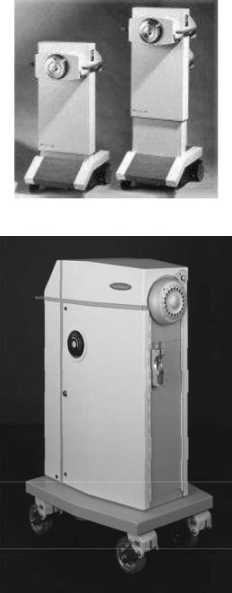
Figure 2. The Varian GammaMed RAL.
Figure 3. The Varian VariSource RAL.
and < 1 mm in diameter, fixed at the end of a steel cable (Figs. 5 and 6). The Nucletron source is placed in a stainless steel capsule and welded to the cable, while the Varian source is placed in a hole drilled into the cable and closed by welding. The 192Ir radionuclide is now used for all HDR
RALs, although early versions of HDR RAL used 60Co. A new source has an activity near 10 Ci. Since 192Ir has a
half-life of 74 days, the source should be replaced every 3 months to keep the treatment in the HDR radiobiological regime. A trained medical physicist calibrates the source after each installation using a re-entrant well-type ionization chamber (Fig. 7). The chambers themselves are calibrated by secondary calibration laboratories known as
BRACHYTHERAPY, HIGH DOSAGE RATE |
591 |
Accredited Dosimetry Calibration Laboratories (ADCL). The resulting source calibration is verified against the manufacturer’s source calibration.
Source Drive Mechanism
When the RAL unit receives a command to initiate a treatment, the stepper motor connected to the reel containing the drive cable turns, causing the source cable to advances from the shielded safe along a path constrained by transfer tubes to the first treated dwell position in the applicator attached to the first channel. The source dwells at that position for a predetermined duration (dwell time) as calculated by the treatment planning system (see below). After completing that dwell, it goes on to the subsequent dwell positions. Some units step as the source drives out (MicroSelectron), stopping first at the dwell position most proximal to the afterloader, while the other (VariSource and Gamma-Med) the source travels first to the most distal dwell (toward the tip of the applicator), and a bit farther, and then steps as the source returns toward the safe. Stepping on the outward drive obviates any concern about the effect of slack in the drive mechanism affecting the accuracy of the source position. The unit that steps on the way back into the unit includes correction for slack in the calibration of the source location. Upon completion of the treatment for the first channel, the source is retracted into the safe, and redirected to travel to the second channel. The process is repeated for all the subsequent treatment channels. The programmed movement of the source is verified by means of an optical encoder or other devices that compare the angular rotation of the stepper motor or cable length ejected or retracted with the number of pulses sent to the drive motor. This system is capable of detecting catheter obstruction or constriction as increased friction in the cable movement. Under certain fault conditions, if the stepper motor fails to retract the source, a high torque direct current (dc) emergency motor will retract the source.
The confirmation of the source exit from and return to the safe is carried out by an ‘‘optopair’’, consisting of a pair of light-sensitive detector and infrared (IR) light source, that detects the cable when its tip obstructs the light path. All the currently marketed after-loaders are also equipped with check cables or dummy sources. The check cable is an exact duplicate of the radioactive source along with its cable, except not radioactive. Before the ejection of the radioactive source, the check cable is first ejected to check the integrity of the catheter system. After a noneventful check by this ‘‘dry run’’ with the dummy source, the radioactive source is then sent for treatment.
Indexer
The RALs are equipped with an indexer, shown in Fig. 8. The indexer consists of an S-tube (item 14 in Fig. 4) that directs the source cable from the exit of the safe to one of the exit ports from the unit (channels). The various catheters or applicator parts connect to these channels, usually through connecting guides called transfer tubes. Different units have between 3 and 24 channels available for

592 |
BRACHYTHERAPY, HIGH DOSAGE RATE |
|
|
|
Table 1. Specific Features of the Three Currently Marketed HDR RALs |
|
|||
|
|
|
|
|
|
|
MicroSelectron V2 |
Gamma Medþ |
VariSource 200/200t |
|
Vendor |
Nucletron |
Varian |
Varian |
|
Sources |
10 Ci of 192Ir |
10 Ci of 192Ir |
10 Ci of 192Ir |
Source dimension |
3.5 mm L, 1.1 mm OD |
4.52 mm L, 0.9 mm OD |
5 mm L, 0.59 mm OD |
|
|
Channels |
18 |
3 or 24 |
20 |
Source extension |
1500 mm |
1300 mm |
1500 mm |
|
Channel length |
Variable |
Fixed |
Variable |
|
Source movement |
Stepping forward |
Stepping backward |
Stepping backward |
|
|
Step sizes |
2.5, 5 or 10 mm |
1–10 mm, 1 mm steps |
2–99 mm, 1 mm steps |
Dwells/channel |
48 |
60 |
20 |
|
Speed of source |
50 cm s 1 |
60 cm s 1 |
50–60 cm s 1 |
|
Figure 4. Schematic diagram of a single stepping source RAL. (Courtesy of Nucletron Corporation, Columbia, MD.)
Figure 6. A 192Ir HDR source for the MicroSelectron at the end of a steel drive cable, as shown in Fig. 5.
connection. If a patient’s treatment requires more than the number of channels on a given treatment unit, the treatment must be broken into sessions, where the catheters are connected up to the number of channels available and treated Then the transfer tubes are disconnected from the catheters just treated and reconnected to the next set of catheters for continuation of the treatment.
Figure 5. Schematics of the two types of sources used in steppingsource RALs. The VariSource is an earlier version, while the new source has a length of 5 mm.
Source diameter |
|
|
|
|
|
|
Cable diameter |
|||||||
|
|
5 mm |
|
|
|
|
|
|
1.1 mm |
|||||
0.6 mm |
|
|
|
|
|
|
|
|
|
|||||
|
|
|
|
|
|
|
|
|
||||||
|
|
3.5 mm |
|
|
|
|
||||||||
|
|
|
|
|
|
|
|
|
|
|||||
|
|
|
|
|
|
|
|
|||||||
|
|
|
|
|
|
|
|
|
|
|
|
|
|
|
|
|
|
|
|
|
|
|
|
|
|
|
|
|
|
|
|
|
|
|
|
|
Iridium |
|
|
|
|
|
|
|
|
|
|
|
|
|
|
|
|
|
|
|
|
|
|
|
|
|
|
|
|
|
|
|
|
|
|
|
|
|
MicroSelectron high dose-rate source |
|
|
|
|
|
|
|
|
|
|||||
|
|
|
|
|
|
|
|
|
||||||
|
|
source |
|
|
|
|
|
|
|
|||||
|
|
|
|
|
|
|
|
|
|
|
|
|
|
|
Source diameter |
Iridum |
Cable diameter |
||||||||||||
|
0.59 mm |
|||||||||||||
0.34 mm |
Source |
|
||||||||||||
|
|
|
|
|
|
|
||||||||
|
|
|
|
|
|
|
|
|
|
|
|
|
|
|
|
|
|
|
|
|
|
|
|
|
|
|
|
|
|
10 mm
VariSource high dose-rate source
BRACHYTHERAPY, HIGH DOSAGE RATE |
593 |
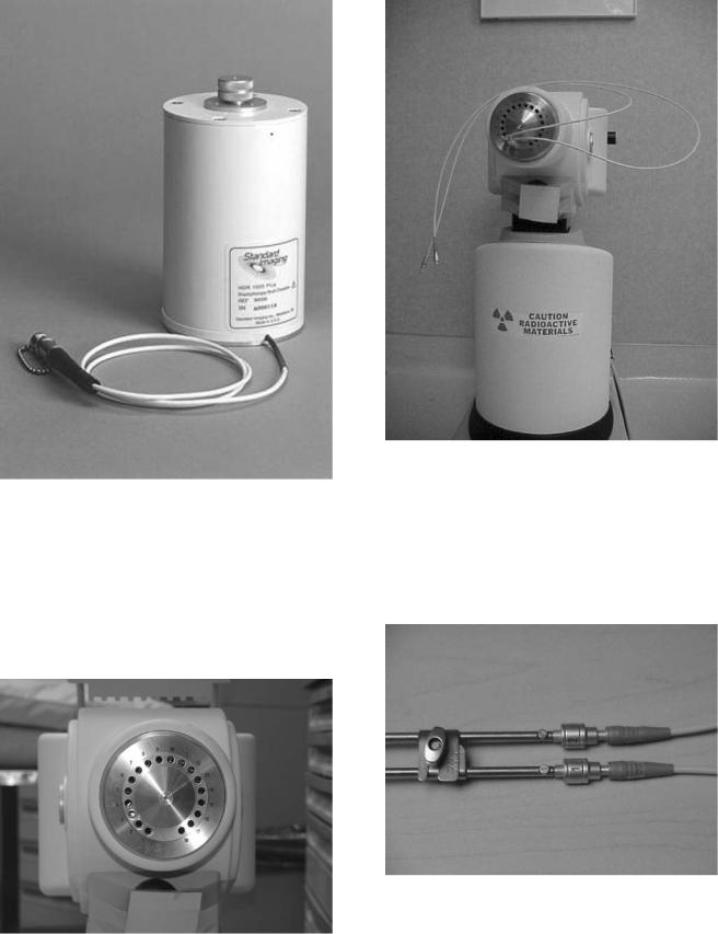
Figure 7. A re-entrant well-type ionization chamber used for calibration of the HDR brachytherapy sources.
Transfer Tubes
Transfer or guide tubes are long tubes that act as a conduit to transfer the source from the RAL to the applicators or catheters for treatment. One end of the transfer tube is attached to the indexer of the RAL (Fig. 9), while the other end is attached to the interstitial, intracavitary, or trans-
Figure 9. A view of two types of transfer tubes hooked up to the indexer of a RAL.
luminal applicators (Fig. 10). The applicator-end of the transfer tube contains spring-loaded ball bearings that block the path through the tube if no applicator is attached. When an applicator is inserted, it pushes aside the ball bearings, opening the path for the source cable. When the
Figure 8. The frontal view of an indexer from the Nucletron, MicroSelectron HDR RAL, consisting of 18 channels.
Figure 10. View of the transfer tubes connected to a gynecological applicator. Ball bearings beneath the gray polymer coating allow verification of the proper connection of the transfer tubes to the applicator. The number 1 and 2 represents that these transfer tubes must connect the channel 1 and 2 of the indexer ring and the similarly numbered parts of the applicator.
594 BRACHYTHERAPY, HIGH DOSAGE RATE
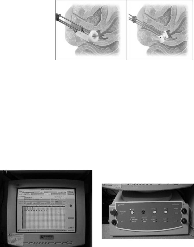
Figure 11. Gynecological applicator used for the treatment of cervical cancer. (Courtesy of Nucletron Corporation, Columbia, MD.)
check cable makes its test run, if no applicator is attached to the transfer tube, the check cable hits the obstacle of the ball bearings, and prevents ejection of the source. Each type of applicator has its own type of transfer tube.
Applicators
An array of applicators for different treatment sites are marketed by each vendor. Each vendor designs their own applicators that can only be used with their transfer tubes and HDR RALs. Figure 11 shows two cervical applicators marketed by Nucletron used for the treatment of cervical cancer.
Treatment Control Station
The treatment control station (Fig. 12) allows the user to select the source travel and dwell sequence to be used in each channel. This can be entered by three ways: (1) manually by the keyboard/mouse at the control station; (2) recalling a standard plan from the computer and then
editing the data without affecting the standard plan from which it originated; or (3) by importing the data from a treatment planning system via transfer medium or a network connection to the treatment control station.
Treatment Control Panel
The treatment control station transfers the data to the treatment control panel. A hard or soft START button initiates the execution of the treatment according to the program. In addition, there is an INTERRUPT button, which when pressed retracts the source and stops the timer, allowing the user to enter the treatment room without receiving radiation exposure. A RESUME or START button resumes the treatment from the time and the dwell position where it was interrupted. A master EMERGENCYOFF button initiates the high torque dc emergency motor to retract the source. In the normal course of a successful termination of the treatment, the timer runs to zero and the machine automatically retracts the source. Figure 13 shows an example of the treatment control panel.
SAFETY FEATURES
The HDR RALs are complicated devices containing very high activity radioactive sources. Serious accidents can
|
Figure 13. The Treatment Control Panel of the Nucletron, micro- |
|
Selectron HDR RAL. The START button is the white button on the |
Figure 12. A view of the monitor of the RAL treatment control |
right side of the panel, while the EMERGENCY OFF button is the top |
station. |
button on the left side of the panel. |
BRACHYTHERAPY, HIGH DOSAGE RATE |
595 |
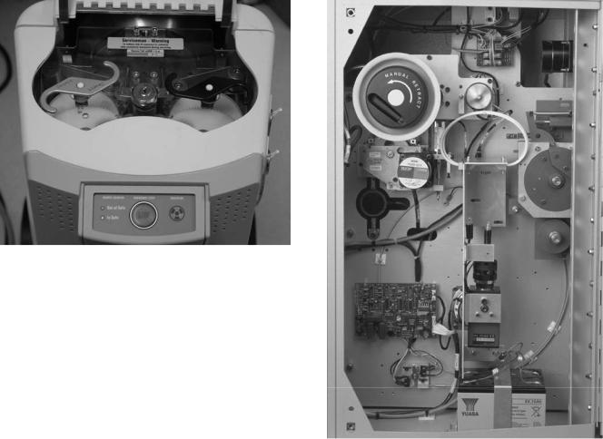
Figure 14. A view of the access panel of the MicroSelectron treatment unit. The center button is an emergency stop button on the treatment unit. Also showing are the manual retraction of the radioactive source cable (left) and the check cable (right).
happen quickly. All such units have many safety features and operational interlocks to prevent errant source movement or facilitate rapid operator response in the event of a system failure.
Emergency Switches
Numerous EMERGENCY OFF switches are located at convenient places and are easily accessible, in case a situation arises. One EMERGENCY OFF switch is located on the control panel. Another EMERGENCY OFF button is located on the top of the remote afterloader treatment head. Vendors usually install one or two emergency switches in the walls of the treatment room. In the event a treatment is initiated with someone other than the patient in the treatment room, that person can stop the treatment and retract the source by pressing the EMERGENCY OFF button. Figure 14 shows the EMERGENCY OFF switch on the treatment unit.
Emergency Crank
All HDR RALs have emergency cranks to retract the source cable if the source fails to retract normally and the emergency motor also fails to reel in the source. Figure 14 shows such a crank for the MicroSelectron and Fig. 15 for the VariSource. Using the crank requires the operator to enter the room with the source unshielded. Exposure rates for this situation are considered below.
Door Interlock
Interlock switches prevent initiation of a treatment with the door open. While in progress, opening the door interrupts the treatment. This safety feature protects the medical personnel from radiation exposure, in the event somebody enters the treatment room without the knowledge of the operator. If a door is inadvertently opened during the treatment, the treatment is interrupted and
Figure 15. The back panel of the VariSource showing the crank for manual source retraction in an emergency.
the source returns to the safe. The treatment can be resumed at the same point where it was interrupted by closing the door and pressing the START or the RESUME button at the control panel.
Audio–Visual System
All HDR brachytherapy suites are equipped with a closed circuit television system (CCTV) or shielded windows and/ or mirrors for observing the patient, and a two-way audio system to communicate with the patient during treatment.
Radiation Monitor and Treatment on Indicator
Three separate independent systems alert personnel when the source is not shielded. One radiation detector is part of the treatment unit and indicates on the control panel when it detects radiation. An independent unit, usually mounted on the treatment room wall with displays both inside and outside the room also alerts the operator and other personnel when the radioactive source is out of the safe. A TREATMENT ON Indicator outside the room, activated when the source passes the reference optical pair discussed above and shown in Fig. 4, also indicates that a treatment is in progress.
596 |
BRACHYTHERAPY, HIGH DOSAGE RATE |
|
|
|
|
Table 2. Exposure Rates from an Exposed 10 Ci 192Ir Source |
|
|
|||
|
|
|
|
Time, min, to Receive |
|
Typical Situation |
Distance, m |
Dose Equiv Rates, Sv h 1 |
|
|
|
10 Gy (likely injury) |
0.5 Sv (annual body limit) |
||||
In Patient |
0.01 |
460 |
1.25 min |
0.07 min |
|
Handling with |
|
|
|
6.5 min |
|
Kelly Clamps, to hands |
0.1 |
4.6 |
2.1 h |
98 min for hand limit |
|
Handling with |
|
|
|
|
|
Kelly Clamps, to body |
0.3 |
0.5 |
18.8 h |
1.0 h |
|
Standing near |
1 |
0.046 |
8.7 days |
11 h |
|
Standing far |
2 |
0.012 |
34.8 days |
43 h |
|
|
|
|
|
|
|
Emergency Service Instruments
In the event the radioactive source fails to retract after termination, interruption, pushing the EMERGENCY SWITCH, or cranking the stepper motor manually, the immediate priority is to remove the source from the patient. Table 2 gives the exposure rates at various distances from a 10 Ci 192Ir source. Table 2 shows that the dose to the patient, with the source in contact, can cause injury in a very short time. On the other hand, the operator, working at a greater distance, is unlikely to receive a dose exceeding regulatory limits for a year, let alone one that would cause health problems. Once the source is removed from the patient and moved to a distance of even a meter, the exposure rate is quite low, and whatever actions need be taken to remove the patient from the room can be performed safely.
The effective annual limit to the body should actually be 10 times < the 0.5 Sv in keeping with the principle to keep exposures as low as reasonable achievable (ALARA), and ideally should not be received in one, short exposure. The allowed exposure to the hands is 15 times that to the body.
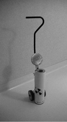
The preferred approach to a source that will not retract by any of the methods is to remove the applicator from the patient as quickly as possible, and place the applicator containing the source in a shielded container (Fig. 16). If it is clear that the cable is caught in the transfer tube and not in the applicator itself, the applicator or catheter may be disconnected from the transfer tube and the source pulled from the applicator. In some cases, this will be faster than removing the applicator. The reason to avoid disconnecting the applicator from the transfer tube is that a source may stay in the applicator if the source capsule shatters. In that case, removing the applicator attached to the transfer tube keeps the system closed, while disconnecting the two opens a path for parts of a broken source to fall from the applicator into body cavities or crevices, or roll onto the floor.
A situation may arise when the source needs to be detached manually from the treatment unit. One (still unlikely) scenario would be if the source were stuck out of the treatment unit, the sources or the closed applicator had been removed from the patient, a person were pinned very close to the source so neither they, nor the treatment unit, could be moved, and the source on the cable could not reach the shielded container. In this special situation, the source cable should be cut from the unit and the source placed in the shielded container always present in the room. In cutting the source cable, it must be clear that the cut is not through the source capsule. For units with the
capsule welded on the cable, the cut must be through the braided cable as opposed to the smooth steel capsule (Fig. 17). For sources imbedded in the cable, a sufficient length of the cable must be seen to assure the cut occurs behind the source. Thus, emergency tools that must be present in the treatment room and always readily accessible include a wire cutter, a pair of forceps, and a shielded service container.
Back-Up Battery
In case of a power failure during the treatment, the machine is equipped with a back-up battery to provide retraction of the source to its safe. The batteries should be tested with each source exchange.
Figure 16. The shielded container for emergency placement of an unretracted source.
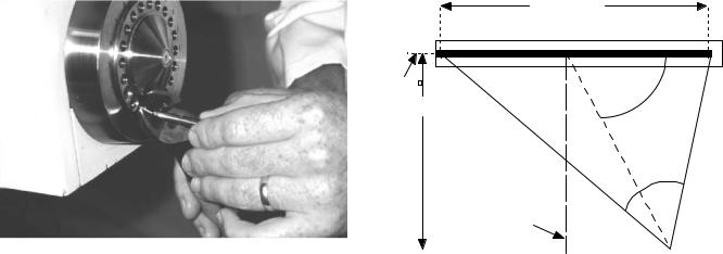
Figure 17. Cutting the source cable from a treatment unit. This procedure should only be performed in very special, rare situations as described in the text. Great care must be taken to assure the cut is through the cable and not the source capsule.
TREATMENT PLANNING SYSTEM
Software and hardware for the treatment planning system are provided by the vendor selling the treatment unit. Three-dimensional (3D) patient data [computed tomography (CT), magnetic resonance imaging (MRI)] can be directly transported and loaded in the planning system. Two dimensional (2D) data (e.g., from radiographs) usually are loaded interactively by computer peripherals (scanners, digitizers) although some automated input systems are available. With 2D input, the target information must be inferred since tumors are generally not visible on the images, while the 3D imaging often visualizes tumors as well as surrounding normal tissue structures. With either input, tumor volume is entered on these images, and the treatment-planning volume is constructed by adding some margin to the tumor volume. Various computer algorithms help the planner conform the prescribed dose to the target volume. Data characteristic for the radioactive source are usually supplied by the vendor and included in the software. The medical physicist enters the source strength data both in the planning system and the treatment unit at the time of the installation of the new source in the treatment unit after calibration.
Dose Calculation
The treatment-planning computer calculates the dose distribution for a patient containing an applicator with a given set of dwell positions, each with their own dwell time. In calculating the dose distribution, the computer first calculates the dose to a set of grid points. Usually, the operator wishes to see the results presented as isodose lines. An isodose line on a given plan connects all points receiving the same dose, much like elevation lines on a contour map of part of the Earth connects points with the same altitude. From the dose values at the grid points, the computer interpolates to find the path of the isodose line
BRACHYTHERAPY, HIGH DOSAGE RATE |
597 |
Active Length (L)
Source |
θ |
axis |
|
|
h |
r
β
Perpendicular
Bisector
P(r,θ)
Figure 18. Geometry and legend for the dosimetry of a line source as given in Eq. 1.
value specified by the user. The calculation of the dose from one dwell position, identified with the subscript i, to a point P(r,) as shown in Fig. 18, uses the formula (1),
Diðri; uÞ ¼ SK L ½Giðr; uÞ=Gðro; uoÞ& giðriÞ Fiðri; uÞ ti ð1Þ
where
Di(ri,u) ¼ The radiation dose to water, in units Gy, at position P(r,u)
SK ¼ The air kerma strength of the source in mGym2 h 1. The strength of photon-emitting brachytherapy sources usually is specified by the intensity of the radiation at some distant outside of the source rather than by the amount of radioactivity contained inside. In this manner, variations in the source encapsulation, which may attenuate varying amounts of the radiation given off by the contained radionuclide, have no effect on the dose delivered to the patient. While the strength of a new HDR source is often quoted as 10 Ci (the approximate activity in the capsule), the actual source strength determination accounts for the energy of radiation from the source, transferred to a mass of air at a given point. Air kerma is the energy transferred from the radiation to kinetic energy in the medium per unit mass, where the medium must be specified. That point for air kerma strength is at 1 m, and a new source would have an air kerma strength of 40 mGy m2 h 1, or in shorthand, 40 kU, where 1 U ¼ mGy m2 h 1. A radiation dose of 1 gray (Gy), equals 1 joule per kilogram (1 J kg).
L ¼ The dose rate constant, that is the absorbed dose rate in cGy h 1 at 1 cm from the source in the perpendicular
plane that bisects the source axis per unit air kerma strength. For 192Ir sources, L ¼ 1.12 cGy h 1/U.
[Gi(ri,ui)/G(ro,uo)] ¼ The geometry function, which accounts for changes in dose rate due to the relative positions of the source and the calculation point and the
598 BRACHYTHERAPY, HIGH DOSAGE RATE
shape of the source. The numerator expresses the geometric dose pattern for the point of calculation while the denominator gives that for the reference condition, where ro ¼ 1 cm and uo ¼ 908. The geometric dose pattern usually is approximated as 1/r2 for a point source, and for a line source /(L h) as shown in Fig. 18.
gi(ri) ¼ The radial dose function, variation in the dose rate with distance from the source due to the attenuation and scatter due to the tissue between the source and the point of calculation at distance r, normalized at 1 cm, and not including any effect in dose rate due to geometry (i.e., the geometric function has been removed from the dose at the calculation distance and at 1 cm for the ratio).
Fi(ri,u) ¼ The anisotropy function, which describes the deviation of the shaped of the isodose lines from a circle. The function Fi(ri,u) ¼ the dose at the calculation point P(r,u) divided by the dose at the same distance, ri but on the perpendicular bisector, that is with uo ¼ 908, and, as with the radial dose function, with the geometrical effects removed.
ti ¼ the dwell time for dwell position i.
Dose Optimization
The treatment planning addresses first which dwell positions will be used. Then for each of the dwell positions, the dwell time must be calculated. The goal is to match the resulting dose distribution with the target volume, a process referred to as optimization. There are several methods to assist the operator in optimizing the dwell times. The methods fall into three main categories:
Analytic methods use relatively simple algorithms to calculate the dwell time for each dwell position. One of the most common, geometric optimization (2,3), weights the dwell time for a position inversely to the sum of the doses to that position from the other dwell positions. For an intracavitary application, where the dose distribution is intended to more or less conform to the shape of the applicator tracks, ‘‘distance optimization’’ is used, where the contributions of all of the other dwell positions are included in the summation of the dose. For interstitial application, where the implant usually treats a volume, the process becomes ‘‘volume optimization’’, with the dose contributions from dwell position along the same track excluded in the summation.
Dose specification methods attempts to calculate the dwell times to deliver a specified dose to designated points (dose points or optimization points) placed throughout the volume or on the surface of the target (4–6). The dose to each specified point described an equation with the dose to the point on one side and the contributions from each of the dwell positions on the other,
allXdwells
Dose ¼ SK L f½Giðri; uÞ=Gðro; uoÞ& giðriÞ fiðri; uÞ tig
i
ð2Þ
In the simplest situation, such an approach becomes solving a set of simultaneous equations for the doses to the optimiza-
tion points for the unknown dwell times. The problem comes when there are more equations than unknowns (more dose points than dwell positions and the set is over determined) or the converse (when the set is underdetermined). In the general case, the set is solved by a least-squares method to find the values for the dwell times that minimizes the square of the difference between the doses desired and the doses resulting from times in the set of equations. However, it is very helpful to add an additional criterion on the dwell times: controlling the fluctuation in dwell times between adjacent positions. The optimization equation becomes
|
All dose points |
ðDjprecribed DjcalculatedÞ2 |
|
||
X2 ¼ |
X |
|
|||
|
|
j¼1 |
|
|
|
|
þ V |
dwells 1 |
all dwells |
ð3Þ |
|
|
X |
ðtiþ1 tiÞ2 þ u |
X ti |
||
|
|
i¼1 |
|
i¼1 |
|
where the first term considers the difference between the prescribed dose and that calculated dose for each specified point. The value of the second term depends on the differences in dwell times between each dwell position and its neighbor. The factor, the dwell weight gradient factor, v, determines how important minimizing this fluctuation is. Large values for v (> 1) tend to force the dwell times to be the same, not producing a very conformal dose distribution; small values (< 0.2) permit negative times to result from the optimization (not a physical situation). The last term minimizes the overall exposure time, assuming that the set of dwell times that adequately treats the target volume with the least total time results in the lowest dose to the rest of the patient. The factor u determines how important minimizing dwell time is for the optimization. The optimized set of dwell times minimizes X2.
Stochastic methods use iterative techniques to find adequate values for the dwell times. Generally, these approaches establish an objective function, such as the difference in dose to a set of point between that prescribed and that achieved. The function may also include penalties for excessive doses to normal tissue structures or lack of homogeneity through an implanted volume. The goal of the optimization is to obtain the best score for the objective function. The process begins with a set of values for the dwell times, evaluates the objective function, and then makes changes in the dwell times. If the new set of times improves the value of the objective function, the new set becomes the current best set. If the old set of times gave a better value for the objective function, it remains the current best set. Obviously, the strategy for how to pick each new set of values in the core of the methodology, and a more complete discussion is beyond the scope of this text. The most common approaches in the literature are simulated annealing (7) and the genetic algorithm (8).
The goal of all the optimization methods is to adequately treat the target tissues while sparing the sensitive normal structures. A resultant plan is shown in Fig. 19.
SHIELDING
The radioactive source in the high dose rate machine starts 10 Ci with an exposure rate at a distance of 1 m from the
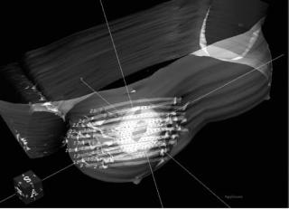
Figure 19. A 3D view of dose distribution of a breast catheter implant with 25 catheters. The inner volume is the tumor volume (lumpectomy cavity), while the outer volume (planning treatment volume) has been generated by adding some margins to the tumor volume. The gray cloud is the dose distribution generated by the treatment planning system.
source of 46 mSv h 1. According to the rules and regulations of the United States Nuclear Regulatory Commission (USNRC), the annual limit for radiation exposure to the public is 1 mSv and the annual occupational limit is 5 mSv. (The actual limit for occupationally exposure persons is 50 mSv year 1, but following the principle of maintaining exposures as low as reasonable achievable, the NRC usually holds licensees to exposure 0.1 of the limit.) In addition to the annual limit, NRC requires that in an unrestricted area the dose equivalent rate should not be > 0.02 mSv in any given hour. Thus, the HDR machine needs to be housed in an adequately shielded room. To meet these requirements in a HDR brachytherapy suite, where the walls and the ceiling are at least 1.5 m from the machine head, concrete wall of 43–50 cm (or 4–5 cm of lead) are needed. For larger rooms the concrete wall thickness will be lower since the exposure rate is inversely proportional to the square of the distance from the radioactive source. For details on the procedures for calculating the thickness of barriers for a particular facility, see health physics texts such as Cember (9) or McGinley (10).
QUALITY ASSURANCE
In order to maintain the quality of patient care, a quality management program is required in every facility that provides HDR brachytherapy treatment. Such a program generally follows standards set by professional organizations and intends to minimize untoward events caused by the malfunction of the machine or human error. Such programs become exceedingly important in HDR brachytherapy because the planning and the treatments tend to happen very quickly, increasing the likelihood of accidents and mistakes. Quality Assurance (QA) tests measure some performance aspect of the treatment unit and compare the results with expectations in order to demonstrate
BRACHYTHERAPY, HIGH DOSAGE RATE |
599 |
proper operation. QA is performed at various intervals: some for each patient, some once each treatment day, and others with each source change. Moreover, for HDR RAL, the USNRC mandates that users meet certain standards, including education and training on operating the machine, emergency procedures, radiation monitoring, pre-treatment safety checks, safe and accurate delivery of the treatment, and monthly/initial calibration of the source. Since the details of quality assurance is outside the scope of this literature, interested readers can refer to the report of Task Groups 59 (11) and 56 (12) of the American Association of Physicists in Medicine and relevant texts (13).
In general, the problem of quality assurance becomes assuring that the treatment will deliver the correct dose, to the correct location, safely. Thus, the tests generally follow the outline below:
Verification of dose variables.
Checking the strength of the source compared with that projected from the initial calibration based on radioactive decay.
Checking the proper operation of the controlling timer.
Verification of position control.
Checking that the source goes to the location programmed.
Checking coincidence between the programmed positions and the respective positions indicated by imaging markers.
Checking consistent movement of the source.
Verification of proper operation of safety features.
Checking operation of the door interlocks. Checking the operation of a handheld radiation
detector.
Checking the operation of the on-board and on-wall radiation detectors.
Checking the operation of the check cable runs and interlocks.
Checking the operation of the EMERGENCY OFF and
TREATMENTINTERRUPT buttons.
COSTS
Currently, two vendors (Nucletron Corporation and Varian Medical Systems) market their RAL treatment unit in the United States. Both the devices requires a capital expenditure of $500,000–750,000, which includes the treatment unit, a variety of transfer tubes, along with the software and hardware for the treatment planning system. Applicators that are needed to be placed in the tumor costs extra. The costs of preparing a shielded room along with ancillary equipment for X-ray imaging and operating room
600 BRACHYTHERAPY, HIGH DOSAGE RATE
procedures can be another $500,000–750,000. Hence, the total cost can run in between $1–1.5 million (14).
ADVANTAGES AND DISADVANTAGES
HDR comparing with LDR brachytherapy offers several advantages and disadvantages. Being aware of these permits safe and effective operation and application of HDR brachytherapy.
Advantages of HDR Brachytherapy
Safety. One of the major advantages of a RAL is the reduction or elimination of radiation exposure to the radiotherapy staff. In conventional LDR, manual afterloading, the radiotherapy staff receives radiation exposure while loading the applicators with the radioactive sources, and the nursing personnel are exposed during patient care through the duration of the treatment (1–4 days). With either HDR or LDR remote afterloading, the radiotherapy personnel are outside the shielded room during the treatment, and hence are exposed to minimal radiation.
Optimization. The design of the HDR RAL with the stepping source allows greater flexibility and control over dose distribution. The stepping source allows optimization of the dose distribution by adjustment of the dwell times for each dwell position in each channel. The dwell times can be varied infinitely, permitting very fine control of the dose distribution. In LDR, either manual or using an RAL, the finite number of activities available (usually four at most) and the larger sources used with manual applications impose a restriction on the ability to conform the dose distribution to the target.
Stability. Because HDR intracavitary treatments take so little time ( 1 h), applicators can be fixed in place much more stably than for the several day treatments using LDR brachytherapy.
Dose Reduction to Normal Tissue. As with stability, the short duration of HDR intracavitary treatments allows displacement of normal tissue structure (i.e., pushing them away from the source paths) to a greater extent than with LDR treatment.
Applicator Size. The small size of the HDR source permits the use of smaller applicators than those required for the LDR applications, increasing the comfort to the patient.
Outpatient Treatment. Almost all HDR patients are treated on an outpatient basis compared to LDR patients who usually are treated as inpatients. Outpatient treatment is more convenient for the patients and generally results in lower overall costs.
Disadvantages of HDR Brachytherapy
Investment. The initial expense of HDR RAL is very high. Machines and site preparation costs can be anywhere between $0.5 and 1 M.
Complexity. The technological complexity of HDR RAL opens the increased probability of errors, and leads to increased regulatory scrutiny.
Compressed Time Frame. As mentioned above, the rapidity with which procedures progress in HDR brachytherapy increases the probability of executing errors.
Radiobiology. As the dose rate increases, the radiosensitivity (damage per unit dose) increases for both normal tissues and tumors. Unfortunately, the radiosensitivity for the normal tissue increases faster than that for tumors, increasing the likelihood of injuring the patient while controlling the tumor. Overcoming this radiobiological handicap requires the use of the advantages of optimization, stability, and dose reduction to normal tissues, in addition to fractionization. As with external-beam radiotherapy delivered using a linear accelerator, which also operates in the HDR regime, spreading the treatments over many smaller fraction delivered over several days reduces the difference in radiosensitivities between the tumor and the normal tissues.
BIBLIOGRAPHY
Cited References
1.Nath R, Anderson LL, Luxton G, Weaver KA, Williamson JF, Meigooni AS. Dosimetry of interstitial brachytherapy sources: Recommendations of the AAPM Radiation Therapy Committee Task Group No. 43. Med Phys 1995;22:209–234.
2.Edmundson GK. Geometry based optimization for stepping source implants. Activity—The Selectron User’s Newsletter 1991;5:22.
3.Edmundson GK. Geometric optimisation: an American view. In: Mould RF, editor. International brachytherapy. Veenendaal, The Netherlands: Nucletron International BV; 1992, p 256.
4.van der Laarse R. Optimization of high dose rate brachytherapy. Activity—The Selectron User’s Newsletter 1989;2:14– 15.
5.van der Laarse R, Edmundson GK, Luthmann RW, Prins TPE. Optimization of HDR brachytherapy dose distributions. Activity—The Selectron User’s Newsletter 1991;5:94–101.
6.van der Laarse, Thomadsen BR, Houdek PV, van der Laarse R, Edmunson G, Kolkman-Deurloo I-KK. Treatment planning and optimization. In: Nag S, editor. High dose rate brachytherapy: a textbook. Armonk, (NY): Futura Publishing Co.,; 1994. p 85–91.
7.Sloboda RS. Optimization of brachytherapy dose distributions by simulated annealing. Med Phys 1992;19:955–964. See also, Sloboda RS, Pearcey RG, Gillan SJ. Optimized low dose rate pellet configuration for intravaginal brachytherapy. Int J Radiation Oncol Biol Phys 1993;26:499–511.
8.Davis L. Handbook of Genetic Algorithms. New York: Van Nostrand Reinhold; 1991.
9.Cember H. Introduction to health Physics. 3rd ed. New York: McGraw-Hill; 1996.
10.McGinley P. Shielding Techniques for Radiation Oncology Facilities 2nd. Madison: Medical Physics Publishing; 2002.
11.Kubo HD, Glasgow GP, Pethel TD, et al. High dose-rate brachytherapy treatment delivery: AAPM Radiation Therapy Committee Task Group No. 59. Med Phys 1998;25:375– 403.
