

- •VOLUME 1
- •CONTRIBUTOR LIST
- •PREFACE
- •LIST OF ARTICLES
- •ABBREVIATIONS AND ACRONYMS
- •CONVERSION FACTORS AND UNIT SYMBOLS
- •ABLATION.
- •ABSORBABLE BIOMATERIALS.
- •ACRYLIC BONE CEMENT.
- •ACTINOTHERAPY.
- •ADOPTIVE IMMUNOTHERAPY.
- •AFFINITY CHROMATOGRAPHY.
- •ALLOYS, SHAPE MEMORY
- •AMBULATORY MONITORING
- •ANALYTICAL METHODS, AUTOMATED
- •ANALYZER, OXYGEN.
- •ANESTHESIA MACHINES
- •ANESTHESIA MONITORING.
- •ANESTHESIA, COMPUTERS IN
- •ANGER CAMERA
- •ANGIOPLASTY.
- •ANORECTAL MANOMETRY
- •ANTIBODIES, MONOCLONAL.
- •APNEA DETECTION.
- •ARRHYTHMIA, TREATMENT.
- •ARRHYTHMIA ANALYSIS, AUTOMATED
- •ARTERIAL TONOMETRY.
- •ARTIFICIAL BLOOD.
- •ARTIFICIAL HEART.
- •ARTIFICIAL HEART VALVE.
- •ARTIFICIAL HIP JOINTS.
- •ARTIFICIAL LARYNX.
- •ARTIFICIAL PANCREAS.
- •ARTERIES, ELASTIC PROPERTIES OF
- •ASSISTIVE DEVICES FOR THE DISABLED.
- •ATOMIC ABSORPTION SPECTROMETRY.
- •AUDIOMETRY
- •BACTERIAL DETECTION SYSTEMS.
- •BALLOON PUMP.
- •BANKED BLOOD.
- •BAROTRAUMA.
- •BARRIER CONTRACEPTIVE DEVICES.
- •BIOCERAMICS.
- •BIOCOMPATIBILITY OF MATERIALS
- •BIOELECTRODES
- •BIOFEEDBACK
- •BIOHEAT TRANSFER
- •BIOIMPEDANCE IN CARDIOVASCULAR MEDICINE
- •BIOINFORMATICS
- •BIOLOGIC THERAPY.
- •BIOMAGNETISM
- •BIOMATERIALS, ABSORBABLE
- •BIOMATERIALS: AN OVERVIEW
- •BIOMATERIALS: BIOCERAMICS
- •BIOMATERIALS: CARBON
- •BIOMATERIALS CORROSION AND WEAR OF
- •BIOMATERIALS FOR DENTISTRY
- •BIOMATERIALS, POLYMERS
- •BIOMATERIALS, SURFACE PROPERTIES OF
- •BIOMATERIALS, TESTING AND STRUCTURAL PROPERTIES OF
- •BIOMATERIALS: TISSUE-ENGINEERING AND SCAFFOLDS
- •BIOMECHANICS OF EXERCISE FITNESS
- •BIOMECHANICS OF JOINTS.
- •BIOMECHANICS OF SCOLIOSIS.
- •BIOMECHANICS OF SKIN.
- •BIOMECHANICS OF THE HUMAN SPINE.
- •BIOMECHANICS OF TOOTH AND JAW.
- •BIOMEDICAL ENGINEERING EDUCATION
- •BIOSURFACE ENGINEERING
- •BIOSENSORS.
- •BIOTELEMETRY
- •BIRTH CONTROL.
- •BLEEDING, GASTROINTESTINAL.
- •BLADDER DYSFUNCTION, NEUROSTIMULATION OF
- •BLIND AND VISUALLY IMPAIRED, ASSISTIVE TECHNOLOGY FOR
- •BLOOD BANKING.
- •BLOOD CELL COUNTERS.
- •BLOOD COLLECTION AND PROCESSING
- •BLOOD FLOW.
- •BLOOD GAS MEASUREMENTS
- •BLOOD PRESSURE MEASUREMENT
- •BLOOD PRESSURE, AUTOMATIC CONTROL OF
- •BLOOD RHEOLOGY
- •BLOOD, ARTIFICIAL
- •BONDING, ENAMEL.
- •BONE AND TEETH, PROPERTIES OF
- •BONE CEMENT, ACRYLIC
- •BONE DENSITY MEASUREMENT
- •BORON NEUTRON CAPTURE THERAPY
- •BRACHYTHERAPY, HIGH DOSAGE RATE
- •BRACHYTHERAPY, INTRAVASCULAR
- •BRAIN ELECTRICAL ACTIVITY.
- •BURN WOUND COVERINGS.
- •BYPASS, CORONARY.
- •BYPASS, CARDIOPULMONARY.
296 BIOMATERIALS: CARBON
derived foams on the growth of murine lung epithelial cells. Key Eng Mat 2003;240–242: 719–724.
References List
Clifford A, Hill R, Rafferty A, Mooney P, Wood D, Samuneva B, Matsuya S. The influence of calcium to phosphate ratio on the nucleation and crystallization of apatite glass-ceramics. J Mater Sci Mater Med 2001;12(5): 461–469.
Healy KE. Molecular engineering of materials for bioreactivity. Curr Op Sol 1999;4: 381–387.
See also BIOMATERIALS FOR DENTISTRY; BONE AND TEETH, PROPERTIES OF;
HEART VALVE PROSTHESES; HIP JOINTS, ARTIFICIAL.
BIOMATERIALS: CARBON
ROBERT B MORE
RBMore Associates,
Austin, Texas
JACK C BOKROS
Medical Carbon Research
Institute
Austin, Texas
INTRODUCTION
Inorganic, elemental carbon is one of the oldest, and yet newest, biomaterials. Carbon utilization began with prehistoric human’s use of charcoal and continues today with a variety of applications exploiting the physicochemical, adsorptive, structural, and biocompatible properties of different forms of carbon. To date, the most important carbon biomaterials have been the isotropic pyrolytic carbons (PyC), produced in a fluidized bed, for use as structural blood contacting components for heart valve prostheses and for small joint orthopedic prostheses. Adsorptive properties of activated carbons also find widespread use for the removal of toxins from the body either by direct ingestion, dialysis, or by plasmapherisis.
Other carbons, such as carbon fibers and glassy carbons have been proposed for use in a variety of structural implants, but because of limited strength and durability, have not been generally accepted. However, carbon fibers and glassy carbons are used as electrodes and electronic components in biomedical analytical devices. Diamond-like coatings have been proposed to provide enhanced wear resistance for large orthopedic components, but this technology is still under development. For the future, carbon holds a central focus in nanotechnology with investigations into the use of fullerenes and carbon nanotubes as means of imaging and manipulating nanoscale bioactive molecules, as selective markers, and perhaps as inhibitors to virulent organisms such as the human immunodeficiency virus (HIV).
Elemental carbon is allotropic, meaning that it can exist in two or more forms (1). There are at least two perfectly crystalline allotropic forms: graphite and diamond, and a myriad of intermediate, imperfectly crystalline, amorphous structures (2). This diversity in structure leads to considerable variability in physical and mechanical properties ranging from graphite, one of the softest materials, to diamond, the hardest material known to human. Thus,
carbon rather than being a single material is actually a spectrum of materials (3). For this reason, it is necessary to qualify the use of the term carbon as designating a generic material with a carbon elemental composition. A specific carbon material must then be qualified with a description of it’s structure.
In general, most of the pure carbons are biocompatible in that they are bioinert, do not provoke thrombosis, hemolysis, inflammatory response, nor activate the complement system (4). Furthermore pure carbons are biostable: toxic products are not generated and the materials retain their properties. However, just because a candidate material is a carbon does not mean that its particular microstructure and properties are appropriate for the desired application. For example, structural applications such as cardiovascular and orthopedic prostheses require strength, fatigue resistance, wear resistance, low friction and durability, in addition to tissue compatibility (3). Not all carbons have the appropriate properties needed for structural use.
In order to appreciate the medically important carbons, some of the various forms of elemental carbon, their synthesis, structure, and properties will be presented and briefly discussed. We will then return to the important carbon biomaterials, discuss their utilization, and conclude with speculations as future directions.
BACKGROUND
Structure of Carbons
Diversity in carbon arises from the electronic configuration: 1s22s22p2;3P, which allows the formation of a number of hybridized atomic orbitals that share four valence electrons to form covalent bonds with directional properties. On the basis of bond structures that arise from the hybridized orbital bonds, carbon compounds are classed as aliphatic and as aromatic (5). Originally, aliphatic meant ‘‘fatty’’ and aromatic meant ‘‘fragrant’’, but these descriptions no longer have any real significance. Aliphatic compounds are further subdivided into alkane, alkenes, alkynes, and cyclic aliphatic. Aromatic compounds are benzenes and compounds that resemble benzene in chemical behavior. With a few exceptions, organic compounds of medical importance tend to be aromatic or benzene-like. Details of electronic structure beyond that given here may be found in standard chemistry and organic chemistry textbooks (1,5).
Naturally Occurring Carbons
Diamond. Diamond is the ultimate polycyclic aliphatic system, but is not a hydrocarbon; rather, it is one of the allotropic forms of elemental carbon. In the diamond allotropic structure, one s and three p orbitals undergo hybridization to form the sp3 orbital that has tetrahedral symmetry. This symmetry allows covalent bonds to connect each carbon atom with four others. Bond angles are 109.5 8 and the carbon–carbon bond length is 0.154 nm. Each carbon is bonded to the original plus three others and this structure propagates throughout the entire crystal forming one giant isotropic molecule of covalently bonded carbons (1,2), as shown in Fig. 1. The diamond crystallographic
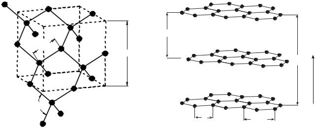
0.154
0.358
109.5 °
Figure 1. Crystallographic structure of diamond with tetrahedral bond angles of 109.58 and bond lengths of 0.154 nm. The unit cell with a length of 0.358 nm is shown by the dashed lines. The spheres represent the location of the atoms and not size.
structure can be visualized as a repetition of the six-carbon cyclohexane ‘‘chair’’ configuration. Because of the large number covalent bonds with an interlocking isotropic orientation, the structure is very rigid. A large amount of energy is required to deform the crystal, hence diamond is the hardest material known.
Graphite. Where diamond is the ultimate polycyclic aliphatic system, graphite is the ultimate polycyclic aromatic system. Graphite has a layered structure consisting of planar arrays in which each carbon atom is bonded by two single bonds and one double bond with its three nearest neighbors. Where diamond can be visualized as a repeated cyclohexane chair, graphite is visualized as a repeated six-carbon benzene ring structure. Within a single plane, each carbon is bonded with a single atomic distance of 0.142 nm to its three nearest neighbors by sp2 orbitals with hexagonal symmetry and 120 8 bond angles (1). Three of the four valence electrons are used to form these regular covalent s (sigma) bonds, which forms the basal planes of hexagonal covalently bonded atoms as shown in Fig. 2. A single basal layer of the hexagonal carbons is known as a graphene structure.
The fourth p (pi) electron resonates between valence structures in overlapping p orbitals forming p bond donutshaped electron clouds with one lying above and one below and perpendicular to the plane of the s bonded carbons (2). Successive layers of the hexagonal carbons are held together at a distance of 0.34 nm by weak van der Waals forces or by interactions between the p orbitals of the adjacent layers (6,7). Thus the graphite structure is highly anisotropic, consisting of stacked parallel planes of strong covalent in-plane bonded carbons with the planes held together by much weaker van der Waals type forces. Because of weak interlayer forces, the layers are easily separated, which accounts for softness and lubricity of graphite. These weak interlayer forces also account for
(a) the tendency of graphitic materials to fracture along
BIOMATERIALS: CARBON |
297 |
0.335
0.67
b
c
a
0.142 |
0.246 |
|
Figure 2. Crystallographic structure of graphite. Basal planes a and b contain the hexagonal covalently bonded carbons with bond angles of 1208 and bond lengths of 0.142 nm. Because of sp2 coordination, each basal plane is shifted one atomic position relative to one another. The successive basal planes are separated by 0.34 nm in the c direction. The distances 0.246 and 0.67 nm are the dimensions of the graphite hexagonal close-packed unit cell.
planes, (b) the formation of interstitial compounds; and (c) the lubricating, compressive, and many other properties of graphite (2,6).
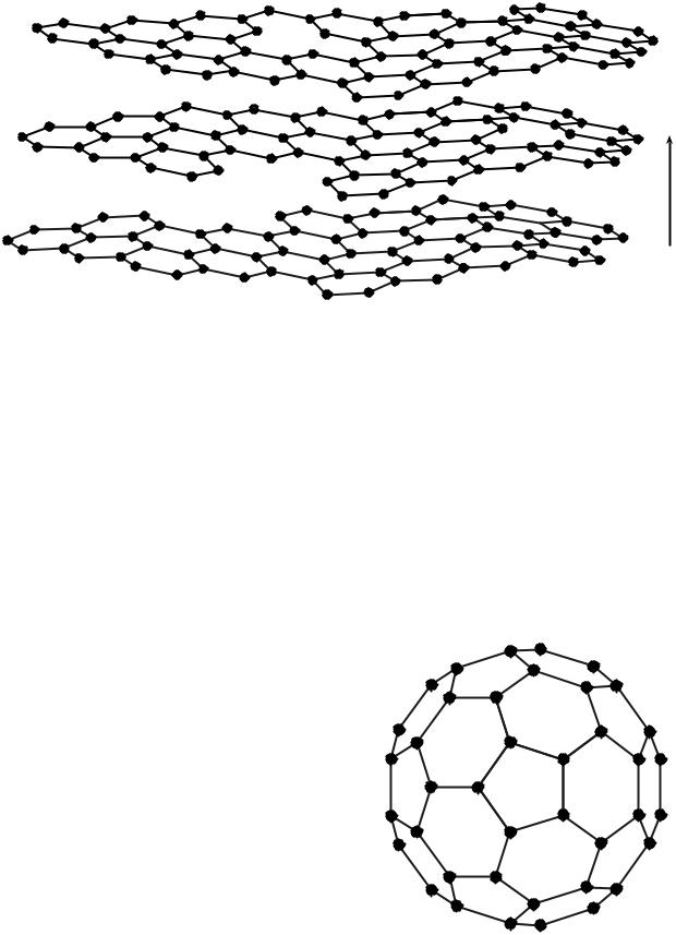
Amorphous Carbons. There are many cystallographically disordered forms of carbon with structures that are intermediate between those of graphite and diamond. The majority tends to be imperfectly layered graphene, turbostratic, and randomly oriented structures (2). X-ray diffraction patterns for amorphous carbons are broad and diffuse because of the small crystallite size, imperfections, and a turbostratic structure (2). In turbostratic structures, there is order within the graphene planes (denoted as a and b), but no order between planes (denoted as c direction) as shown in Fig. 3. Crystallographic defects such as lattice vacancies, kinked or warped layer planes, and possible aliphatic bonds tend to increase the turbostratic layer spacing relative to graphite and inhibit the ability of the layer planes to slip easily as occurs in graphite (2). Like graphite, there is strong in plane covalent bonding, but, because the ability of the planes to slip past one another is inhibited, the materials are much harder and stronger than graphite. Turbostratic carbons occur in a spectrum of amorphous ranging through mixed-amorphous structures and include materials such as soot, pitch, and coals.
Fullerenes. The recently discovered fullerenes (2,8,9) can occur naturally as a constituent of soot. Fullerenes are hollow cage-like structures that can be imagined as graphene sheets that have been folded or rolled into a ball or cylindrical tube. However, the structures are actually formed by the reassociation of individual carbon atoms rather than a folding or rolling of a graphene structure. The most famous fullerene is the 1 nm diameter C60
298 BIOMATERIALS: CARBON
b
c
a
Figure 3. Turbostratic amorphous structure.
(60 carbon) buckministerfullerene (bucky ball) with a truncated icosahedron structure that resembles a European football. Because the structure is reminiscent of the geodesic dome designed by the architect Buckminister Fuller, the proposed structure was named after him (8).
Geometrically, the bucky ball has a repeating structure that consists of a pentagon surrounded by five hexagons (see Fig. 4). In order to wrap into a nonplanar ball, the graphitic p orbitals must assume an angle of 101.6 8 relative to the plane of the C bonds rather than 90 8 for graphite
(9). There are a number of other possible carbon number ball structures, but the smallest sizes are thought to be limited to C60 and C70 by the molecular strain induced at the edge-sharing pentagons. Although remarkably stable, C60 can photodisassociate when pulsed with laser light and loose carbon C2 pairs down to C32, where it explodes into open fragments because of strain energy (10).
Metals can also be inserted into the buckyball cage simply by conducting fullerene synthesis in the presence of metals (11). Such internally substituted endohedral fullerenes are fancifully called ‘‘dopyballs’’ for doped fullerenes (12) and denoted as MaCn, where Ma is the metal and Cn the carbon complex. ‘‘Fullerite’’ refers to a solidstate association of individual C60 molecules, named by analogy to graphite, in which the bucky balls assume a face-centered cubic (fcc) crystallographic structure with lattice constant a ¼ 1.417 nm (13). Treatment of fullerite with 3 equiv of alkali metal, A3C60, makes it a super conductor at room temperature (14), whereas treatment with 6 equiv of alkali metal, A6C60, makes it an insulator.
An excellent introduction to fullerenes by Bleeke and Frey, Department of Chemistry, Washington University, St. Louis, MO, is available on the Internet at http://www.che-
˜
mistry.wustl.edu/edudev/Fullerene/fullerene.html (15).
here. A nanotube consists of a single graphene sheet SWNT (single-wall nanotube) or multiple concentric graphene sheets MWNT (multiwall nanotube) rolled into a cylindrical tube (16). In MWNT, the nested concentric cylinders are separated by the 0.34–0.36 nm graphite layer separation distance.
There are several different wrapping symmetries to give chiral, zigzag or arm chair nanotubes and the tubes may be end capped by a bucky ball half-sphere. Lengths range from well >1 mm and diameters range from 1 nm for SWNT to 50 nm for MWNT. A zigzag SWNT is shown in Fig. 5. Additional information regarding nanotubes can be found at Tomanek’s laboratory, at the University of Michigan. A very informative web page dedicated to nanotubes (17) is at http://www.pa.msu.edu/cmp/csc/nanotube.html.
Nanotubes. Although most likely synthetic, because of |
Figure 4. A surface view of a C60 structure, buckministerfuller- |
the basic fullerene structure, nanotubes will be discussed |
ene (buckyball), with an 1 nm diameter, is shown. |
|
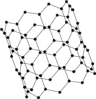
Figure 5. A short section of SWNT with a zigzag chiral symmetry is shown. The arrow indicates the long axis of the tube and bonds on the forward wall are more heavily drawn. Like the buckyball, this SWNT has a diameter of 1 nm.
Synthetic Carbons
Carbon structures can be synthesized through a variety of processes. Because these processes define the resulting materials, both will be presented together. The most important synthesis processes include carbonization or pyrolysis and graphitization (2). Carbonization is a thermal process in which an organic precursor is converted into an all carbon residue with the diffusion of non-carbon volatile compounds to the atmosphere (2,6). The resulting all-car- bon residue is known as a coke or a char.
Coke is a graphitizable carbon and chars are nongraphitizing (2). Cokes and chars are amorphous, lacking longrange crystallographic structure (turbostratic), with the degree of structure dependant on the precursor and the particular carbonization process. A coke may then be graphitized. In graphitization, residual non-carbon impurities are removed and the turbostratic structure is converted into a well-ordered graphite crystallographic structure by heating to high temperatures (6). A char, when graphitized retains its disordered turbostratic structure (2).
Synthetic Graphites. These carbons are prepared by grinding or milling a solid precursor material (coke) into fine particles, binding with a material such as coal tar pitch, and then molding into shape (2,6). The resulting material is then carbonized baked and graphitized. Typical milled grain sizes may range from 1 mm up to 1 cm. The mixture of filler and binding may be doped or impregnated with the addition of non-carbon elements such as tungsten. The final properties of the molded graphite depend on the degree of graphitization and the grain size (6). Other
BIOMATERIALS: CARBON |
299 |
important parameters are porosity, anisotropy, and density (6). One synthetic graphite used in medical devices, POCO AXF 5Q, has a grain size of 5 mm, a pore size of 0.6 mm, and a 23% volume total porosity. This particular graphite grade is often mixed with 10% by weight fine powdered tungsten before molding and baking to confer radio opacity (6).
Viterous, Glassy Carbons. Carbonization of certain polymer chars produces glassy carbons. These materials are amorphous, turbostratic, and thought to contain some sp3 character in addition to sp2(2). Precursors are polymers such as phenolformaldehyde, poly(furfuryl alcohol) and poly(vinyl alcohol). Shapes are attained by carbonization in molds and are limited to 7 mm thickness because of volumetric shrinkage ( 50%) and the need for gases generated during carbonization to diffuse out and not nucleate bubbles (18). The resulting material is hard, brittle, and difficult to machine.
Carbon Fibers. Thomas Edison produced the first carbon fiber in 1879 as a filament of an incandescent lamp and the first patent was issued in 1892 (2,3). Hiram Maxim received a process patent for the production of carbon fibers in 1899 (3). However, prior to the 1950s carbon fibers were of marginal strength and used primarily for their electrical properties.
Carbon fibers are highly oriented, small (with diameters on the order of 7 mm), crystalline filaments that are prepared by carbonization of polymeric filament precursors and sequential heat treatment. There are three classes of fibers based on the precursor material: PAN (polyacrylonitrile), rayon, and pitch (2). Other precursors and processes exist, but have not been as successful commercially (3). In general, fibers are classified according to structure and degree of crystallite orientation (2): high modulus (345 GPa and above), intermediate modulus (275 GPa), and low modulus (205 GPa and below). Structures are turbostratic and can contain mixed sp2 and sp3 bonding (2). Because of their small volume, tensile strengths can be quite high, on the order of 1000–7000 MPa.
Chemical Vapor Deposited (CVD) Carbons. Carbonization of a gaseous or liquid precursor such as gaseous hydrocarbons produces a material known as pyrolytic carbon or pyrolytic graphite (2). Thermal decomposition of hydrocarbons produces carbon free radicals in the vapor phase, which can then polymerize to form coatings on exposed surfaces. Common precursor hydrocarbons are methane, propane, and acetylene. The resulting turbostratic pyrolytic carbons can be isotropic or anisotropic depending on the pyrolysis reaction conditions (19). The coating process can be prolonged so as to produce structural components for heart valve and orthopedic prostheses with coating thickness on the order of 1 mm.
The pyrolytic carbons for medical applications are formed by CVD processes in fluidized-bed reactors (20). Propane is the precursor gas and an inert gas such as nitrogen or helium provides the levitation needed to fluidize a bed of small refractory particles. Graphite preformed substrates (e.g., POCO AXF 5Q) suspended in the fluidized

300 BIOMATERIALS: CARBON
bed are coated with the pyrolytic carbon (20). The resulting coating structures are turbostratic and isotropic with very small randomly oriented crystallites: These crystallites will henceforth be designated as isotropic fluidized-bed pyrolytic carbons. Nonfluidized-bed CVD reactors tend to produce a highly anisotropic coating with column-like, (columnar) crystallites or laminar structures with the basal planes oriented parallel to the deposition surface (2,19).
Highly Oriented Pyrolytic Graphite (HOPG). Columnar and laminar pyrolytic carbons when annealed >2700 8C are reordered, the turbostratic imperfections disappear and the resulting structure closely approaches the ideal graphite structure with an angular spread of the crystallite c axes of <1 8 (2).
Vapor-Phase Carbons. Carbon CVD coatings formed from solid precursors carbonized by vaporization are considered vapor-deposited coatings (VPC). Precursors can be graphite or vitreous carbon vaporized by heating to high temperature at low pressure to generate the carbon free radicals. This technique produces line-of-sight coatings of nanometer and micrometer level thickness. The VPC coatings tend to be turbostratic and amorphous (3).
Diamond-Like Carbon. Diamond-like carbon coatings containing mixed sp3 and sp2 bonds can be prepared by physical vapor deposition (PVD). These PVD methods produce carbon free radicals by ion beam sputtering, or laser or glow discharge of solid carbon targets. There are also mixed PVD/CVD methods such as plasma or ion beam deposition from hydrocarbon gas precursors (2).
Activation. Activated carbons have large surface areas and large pore volumes that lend to a unique adsorption
capability (21). Activation is a thermal or chemical treatment that increases adsorption capability. The mechanisms for adsorption are complex and include physical and chemical interactions between the carbon surface and the sorbed substances. Activity includes (a) adsorption, (b) mechanical filtration, (c) ion exchange, and (d) surface oxidation (22). Of these, adsorption and surface oxidation are the most important for medical applications. Incompletely bonded basal plane carbons as occur at crystal edges exposed at the surface, as well as defects, are chemically active and can chemisorb substances, particularly oxidizing gases such as carbon monoxide and carbon dioxide (23). Surface oxidation involves the chemisorbance of atmospheric oxygen and further reaction of the sorbed oxygen with other substances (24). Physical adsorbance occurs because of charge interactions, and chemical adsorbance occurs because of reactions between the adsorbant and adsorbate (24).
Any high carbon material can be ‘‘activated’’ by various oxidizing thermal and chemical processes that increase porosity and active surface area, which increases the ability for chemisorption (25). A char is formed and then treated chemically or physically to generate pores and the surface oxidized (21). Surface oxide complexes such as phenols, lactones, carbonyls, carboxylic acids, and quinones form that have a strong affinity for adsorbing many substances such as toxins or impurities (26). Carbon fibers may be activated in order to enhance the ability to bind with a matrix material when used as a filler.
PROPERTIES
Representative physical and mechanical properties of the carbon allotropes are summarized in Table 1 (2,3,27). Materials included span the spectrum from natural diamond to natural graphite. There is considerable variability
Table 1. Representative Mechanical and Physical Properties for Carbon Allotrophs
|
Natural |
Amorphous |
|
Natural |
Property |
Diamond |
Carbons |
HOPG |
Graphite |
|
|
|
|
|
Density, g cm 3 |
3.5–3.53 |
1.45–2.1 |
2.25–2.65 |
2.25 |
Young’s modulus, GPa |
700–1200 |
17–31 |
20 |
4.8 |
Hardness, mohs |
10 |
2–5 |
|
1–2 |
Hardness, DPH 500 g |
|
150–(>230) |
|
|
Flexural strength, MPa |
|
175–520 |
80 (c) 120 (ab) |
|
Compressive yield strength, MPa |
8680–16530 |
700–900 |
100 |
|
Fracture toughness, MPa m1/2 |
3.4 |
0.5–1.67 |
|
|
Poisson’s ratio |
0.1–0.29 |
0.2–0.28 |
|
|
Wear resistance |
Excellent |
Poor to excellent |
Poor |
Poor |
Electrical resistivity, V cm |
2700 |
|
0.15–0.25 (c) |
0.006 |
6 |
5.9 |
|
3.5 10 5–4.5 10 5(ab) |
6 |
Magnetic susceptibility, 10 |
|
|
||
emu/mol |
|
|
|
|
Melting point, 8C |
3550 |
|
3650 |
3652–3697 |
|
|
|
|
(sublimes) |
Boiling point, 8C |
4827 |
|
0.1 (ab) 20 (c) |
4220 |
CTE linear, (208C)mm (m 8C) 1 |
1.18 |
2.6–6.5 |
0.6 (ab) 4.3 (c) |
|
Heat capacity, J/g 8C |
0.4715 |
|
|
0.69 |
Thermal conductivity, W (m K) 1 |
2000 |
4.6–6.3 |
16–20 (ab) 0.8 (c) |
19.6 (ab) 0.0573 (c) |
aValues from Matweb.com and from Refs. (2,3).

BIOMATERIALS: CARBON |
301 |
in properties depending on the structure, anisotropy, and crystallinity, particularly in the amorphous carbons. Physical properties such as resistivity, coefficient of thermal expansion, thermal conductivity, and tensile strength (28) show profound sensitivity to direction in the graphitic materials. This anisotropy is most easily seen in HOPG by comparing the ab direction, parallel to the s-bonded basal plane, to the perpendicular c direction. For example, the resistivity drops for HOPG because of the mobility of the p-electron clouds in the ab direction relative to the c direction (2). Diamond, with full covalent bonding, is an insulator.
Thermal conductivity, which occurs by lattice vibration, is related to a mean-free-path length for wave scattering. Little scattering occurs in the near-perfect graphite crystal basal plane, so the scattering path length and thermal conductivity are high in the ab direction. In the c direction, thermal conductivity is much lower because the amplitude of lattice vibration is considerably lower than for the ab direction (2). Thermal expansion is related to the interatomic spacing of the carbon atoms, bond strength, and vibration. As temperature increases, the atoms vibrate and the mean interatomic spacing increases. For weak bonding in the c direction, the interatomic vibrational amplitude and dimensional changes are larger than for the strongly bonded ab direction (2). The CTE values are stated for room temperature to 200 8C; the negative values shown in Table 1 are possibly due to internal stresses and become positive at higher temperatures. Large anisotropic differences in CTE can result in large internal stresses and possible structural problems with heating and cooling over large temperature differences.
BIOCOMPATIBILITY
Pyrolytic carbons used in heart valve and orthopedic prostheses have a successful clinical experience as long-term implant materials for blood and skeletal tissue contact (3,29–31). These isotropic, fluidized-bed, pyrolytic carbons that were originated at General Atomics in the 1960s demonstrate negligible reactions in the standard Tripartite and ISO 10993-1 type biocompatibility tests. Results from such tests are given below in Table 2 (20). This material is so nonreactive that it has been proposed as a negative control for these tests. However, the surface is not totally inert and is capable of adsorption and desorption of a variety of substances including protein (32–39). The mechanism for biocompatibility is yet poorly understood,
Table 2. Biological Testing of Pure PyC
but probably consists of a complex, interdependent, and time-dependent series of interactions between the proteins and the carbon surface (32).
Because of the similarity in surface sp2 and sp3 character among the various pure carbons, most can be expected to have the tissue compatibility and biostability to perform well in these biocompatibility tests also. Vitreous carbons (40), activated carbons, and diamond-like coatings (41) are known to exhibit tissue compatibility, likewise the fullerenes will probably be found tissue compatible. As an extreme example, in testing the safety of an activated charcoal for hemoperfusion, Hill (42) introduced finely ground charcoal suspensions into the blood stream of rats in varying concentrations up to 20 mg/kg charcoal and observed no differences in survival or growth relative to controls over a 2-year observation period.
A reasonable working definition for biocompatibility has been given by Williams (43) as, ‘‘The ability of a material to perform with an appropriate response in a specific application’’. The important point here is that while many carbons provoke a minimal biological reaction, ‘‘the specific application’’ demands a complete set of mechanical and physical properties, in addition to basic cell compatibility. Because there are a number of possible microstructures, each with different properties, a given carbon will probably not have the entire set of properties needed for a specific application. Historically, the clinically successful isotropic, fluidizedbed, pyrolytic carbons required extensive development and tailoring to achieve the set of mechanical and physical properties needed for long-term cardiovascular and orthopedic applications (20,30–32).
Blood compatible glassy carbons, for example, are often proposed for use in heart valves. However, glassy carbons were evaluated in the early 1970s as a replacement for the polymer Delrin in Bjork–Shiley valve occluders and actually found to have inferior wear resistance and durability relative to the polymer (44). Thus, the fact that a material is carbon, a turbostratic carbon, or a pyrolytic carbon and is cell compatible, does not justify its use in a long-term implant devices (3,32,33). The entire range of physical and mechanical properties as dictated by the intended application are required.
MEDICAL APPLICATIONS
Activated Charcoal–Activated Carbons
Charcoal, the residue from burnt organic matter, was probably one of the first materials used for medical and
Test description |
Protocol |
Results |
|
|
|
Klingman maximization |
ISO/CD 10993-10 |
Grade 1; not significant |
Rabit pyrogen |
ISO/ DIS 10993-11 |
Nonpyrogenic |
Intracutaneous injection |
ISO 10993-10 |
Negligible irritant |
Systemic injection |
ANSI/AAMI/ISO 10993-11 |
Negative—same as controls |
Salmonella typhimurium Reverse mutation assay |
ISO 10993-3 |
Nonmutagenic |
Physiochemical |
USP XXIII, 1995 |
Exceeds standards |
Hemolysis–rabbit blood |
ISO 10993-4/NIH 77-1294 |
Nonhemolytic |
Elution test, L929 mammalian cell culture |
ISO 10993-5, USP XXIII, 1995 |
Noncytotoxic |
|
|
|
302 BIOMATERIALS: CARBON
biocompatible applications. Prehistoric humans knew that pulverized charcoal could be placed under the skin indefinitely without ill effects, thus allowing decorative tattoos (45). Because granulated charcoal has an active surface area, it can adsorb toxins when ingested. Likewise, charcoal has long been used to clear water and other foods. The ancient Egyptians first recorded the medical use of charcoal 1500 BC (21). During the 1800s, the first formal scientific studies of charcoal as an antidote to treat human poisoning appeared in Europe and The United States. In some of these studies, the researchers demonstrated charcoals effectiveness by personally ingesting charcoal along with an otherwise fatal dose of strychnine or arsenic (21). Activation was discovered 1900 and activated charcoals were used as the sorbant in World War I gas masks (21).
Today’s activated carbons or activated charcoals are derived from a number of precursor organic materials ranging from coal, wood, coconut shells, and bone. Chars are prepared by pyrolyzing the starting organic material using heat in the absence of oxygen. The char is then activated by treatment with chemicals or steam. Activated carbon has remarkable adsorptive properties that vary with the starting material and activation process. Common active surface areas are on the order of 1000–2000 m2/g. Prior to the discovery of activation processes, charcoals were naturally oxidized by exposure to the atmosphere and moisture, as in charcoal, or oxidized in a more controlled activating process (46).
Orally administered activated carbon applications include use as an antidote to poisoning and to drug overdoses, where it acts at the primary site of drug adsorption in the small intestine. There are no contraindications for patients with intact GI tracts. There are numerous advantages and few disadvantages. One of the main disadvantages is that it is unpleasant for the health care professional to use because it can be messy, staining walls, floors, clothing, and so on. It may also be unpleasant to swallow because of a gritty texture (46).
There are extracorporal, parenteral, methods such as hemoperfusion, hemofilteration, and plasmapheresis where activated carbon is used to remove toxins from a patient’s blood. The patient’s heparinized blood is passed via an arterial outflow catheter into an extracorporal filter cartridge containing the activated carbon and then returned to the patient via a venous catheter. These techniques are effective when there is laboratory confirmation of lethal toxin concentrations in the blood and for poorly dialyzable and nondialyzable substances (47).
Pyrolytic Carbons
Isotropic, fluidized-bed PyCs, appropriate for cardiovascular applications originated at General Atomics in the late 1960s as a cooperative effort between an engineer, Jack Bokros, working with pyrolytic carbons as coatings for nuclear fuel particles and a surgeon, Vincent Gott, who was searching for thromboresistant materials for cardiovascular applications (48). Together, they tailored a specific fluidized-bed, isotropic pyrolytic carbon alloy with the biocompatibility, strength and durability needed for long-term structural applications in the
cardiovascular system. The original material was a patented silicon-alloyed pyrolytic carbon given the tradename ‘‘Pyrolite’’ (20).
In the early 1960s, heart valve prostheses constructed from polymers and metal were prone to early failure from wear, thrombosis, and reactions with the biological environment. Prosthesis lifetimes were limited to several years because of wear in one or more of the valve components. Incorporation of PyC as a replacement for the polymeric valve components successfully eliminated wear as an early failure mechanism. Subsequently, in most valve designs, metallic materials were replaced with PyC also (20,29–33,49).
During the 1970s and 1980s Pyrolite was only available from a single source until the original patents expired. Since that time, several other sources have appeared with copies of the original silicon-alloyed General Atomics material. In the early 1990s, the Bokros group revisited the synthesis methods and found that with the then available technology for process control, that a pure carbon pyrolytic carbon could be made with better mechanical properties and potentially better biocompatibility than the original silicon-alloyed Pyrolite (20). This new pure isotropic, flui- dized-bed, pyrolytic carbon material was patented and named On-X carbon. On-X carbon is currently utilized in mechanical heart valves and in small joint orthopedic applications.
These PyC materials are turbostratic in structure and isotropic with fine randomly oriented crystallite sizes on the order 2.5–4.0 nm and c layer spacing of 0.348 nm (50–52). Implants are prepared by depositing the hydrocarbon gas precursor coating in a fluidized bed on to a preformed graphite substrate to a thickness of 0.5 mm (29–32,53). The coatings then may be ground and polished if desired and subjected to a proprietary process that minimizes the degree of surface chemisorbed oxygen.
Some of the mechanical and physical properties of the pure and silicon-alloyed PyC materials appropriate for use in long-term implants are given Table 3 (3,20). A typical glassy carbon and a fine-grained synthetic graphite are also included for comparison. The PyC flexural strength, fatigue, and wear resistance provide adequate structural integrity for a variety of implant applications. The density is low enough to allow components to be actuated by flowing blood. Relative to orthopedic applications, Young’s modulus is in the range reported for bone (54,55), which allows for compliance matching and minimizes stress shielding at the prosthesis bone interface. The PyC strain-to-failure is low relative to ductile metals and polymers; but it is high relative to ceramics. Because PyC is a nearly ideal linear elastic material, component design requires the consideration of brittle material design principals. Certain properties such as strength vary with the effective stressed volume, or stressed area as predicted by Weibull theory (56). Table 3 strength levels were measured for specimens tested in four-point bending, thirdpoint loading (57) with an effective stressed volume of 1.93 mm3. The Weibull modulus for PyC is 10 (57).
Fluidized-bed isotropic PyCs are remarkably fatigue resistant. There is strong evidence for the existence of a fatigue threshold that is very nearly the single cycle
|
|
|
BIOMATERIALS: CARBON |
303 |
|
Table 3. Biomedical Fluidized-Bed Pyrolytic Carbon Properties |
|
|
|
||
|
|
|
|
|
|
Property |
Pure PyC |
Typical Si-Alloyed PyC |
Typical Glassy Carbon |
POCO Graphite AXF-5Q |
|
|
|
|
|
|
|
Flexural strength, MPa |
493.7 12 |
407.7 14.1 |
175 |
90 |
|
Young’s modulus, GPa |
29.4 0.4 |
30.5 0.65 |
21 |
11 |
|
Strain-to-failure, % |
1.58 0.03 |
1.28 0.03 |
|
0.95 |
|
Fracture toughness, MPa Hm |
1.68 0.05 |
1.17 0.17 |
0.5–0.7 |
1.5 |
|
Hardness, DPH, 500 g load |
235.9 3.3 |
287 10 |
150 |
120 |
|
Density, g cm 3 |
1.93 0.01 |
2.12 0.01 |
<1.54 |
1.78 |
|
CTE, mm cm 1 EC |
6.5 |
6.1 |
|
7.9 |
|
Silicon content, % |
0 |
6.58 0.32 |
0 |
0 |
|
Wear resistance |
Excellent |
Excellent |
Poor |
Poor |
|
|
|
|
|
|
|
fracture strength (58–60). Paris-law fatigue crack propagation rate exponents are high; on the order of 80 and da/ dN fatigue crack propagation testing displays clear evidence of a fatigue crack propagation threshold (58–63).
Crystallographic mechanisms for fatigue crack initiation and damage accumulation are not significant in the PyC at ambient temperatures (59,61). There have been no clear instances of fatigue failure in a clinical implant during the accumulated 30-year experience (64). Less than 60 out of >4 million implanted PyC components have fractured (65), and these were caused by damage from handling or cavitation (66–68).
The PyC wear resistance is excellent. Wear testing performed in the 1970s identified titanium alloy, cobalt chromium alloy, and PyC as low wear contact materials for use in contact with PyC (69,70). This study determined that wear in PyC occurred due to an abrasive mechanism and interpreted wear resistance as approximately proportional to the ratio H2/2E, where H is the Brinell hardness number and E is Young’s modulus. This criteria is related to the amount of elastic energy that can be stored in the wearing surface (70). The greater the amount of stored energy, the greater the wear resistance. Successful low wearing contact couples used for mechanical heart valves include PyC against itself, cobalt chromium alloy, and ELI titanium alloy.
Observed wear in retrieved PyC mechanical heart valve prosthesis implant components utilizing PyC coupled with cobalt chromium alloy is extremely low with PyC wear mark depths of < 2 mm at durations of 17 years (71–73). Wear in the cobalt chromium components was higher, 19 mm at 12 years (71–73). But, wear in the cobalt chromium components was concentrated at fixed contact points instead of being distributed over a large area as for the PyC rotating disk. Wear depths in all PyC prostheses, with fixed contact points are also low, <3.5 mm at 13 years (74,75). In contrast, the wear depths in valves utilizing polymeric components such as the polyacetyl Delrin in contact with cobalt chromium and titanium alloys are much higher at 267 mm at 17 years (76). Incorporation of PyC in heart valve prostheses has eliminated wear as a failure mode (29,77).
The PyC is often used in contact with metals and behaves as a noble metal in the galvanic series. Testing using mixed potential corrosion theory and potentiostatic polarization has determined that no detrimental effects occur for PyC coupled with titanium or cobalt–chrome alloys (78,79). Use of PyC with stainless steel alloys is not recommended.
To date, PyC has been used in 25 mechanical heart valve prosthesis designs. One such design, the On-X valve, by Medical Carbon Research Institute, http://www.mcritx. com, is shown in Fig. 6.
Pyrolytic carbon has a good potential for orthopedic applications because of advantages over metallic alloys and polymers (3,30,31):
1.A modulus of elasticity similar to bone to minimize stress shielding.
2.Excellent wear characteristics.
3.Excellent fatigue endurance.
4.Low coefficient of friction.
5.Excellent biocompatibility with bone and hard tissue.
6.Excellent biocompatibility with cartilage.
7.Fixation by direct bone apposition.
A brief comparison of PyC properties to those of conventional/orthopedic implant materials is given in Table 4. Pyrolytic carbon coatings for orthopedic implants can reduce wear, wear particle generation, osteolysis aseptic loosening, and thus extend implant useful lifetimes. Furthermore, good PyC compatibility with bone and the native joint capsule enables conservative hemiarthroplasty replacements as an alternative to total joint replacement.
Cook et al. (80) studied hemijoint implants with a PyC femoral head in the canine hip and observed a greater potential for acetabular cartilage survival in PyC than for cobalt–chromium–molybdenum alloy and titanium alloy femoral heads. There were significantly lower levels of gross acetabular wear, fibrillation, eburnation, glycosaminoglycan loss, and subchondral bone change for PyC than the metallic alloys.
Tian et al. (81) surveyed in vitro and clinical in vivo PyC orthopedic implant studies conducted during the 1970s through the early 1990s and concluded that PyC demonstrated good biocompatibility and good function in clinical applications.
A 10-year follow-up of PyC metacarpophalangeal (MCP) finger joint replacements implanted in patients at the Mayo Clinic, Rochester Minnesota (82) between 1979 and 1987, demonstrated excellent performance. Ascension Orthopedics was able to use these results in part to justify a FDA premarket approval application (PMA) for the semiconstrained, uncemented MCP finger joint replacement, PMA P000057, Nov. 2001.
304 BIOMATERIALS: CARBON
Figure 6. On-X prosthetic heart valves manufactured by Medical Carbon Research Institute from the elementally pure, fluidized-bed isotropic pyrolytic carbon, On-X carbon. The valves consist of a central flow circular orifice with two semicircular occluder disks. A polymeric sewing cuff is used to attach the valve to the annulus tissue. Aortic and mitral valves with two different sewing cuff designs each are shown.
Currently, Ascension Orthopedics, http://www.ascensionortho.com, manufactures PyC prostheses for finger joints: metacarpophalengeal (MCP) and proximal interphalangeal (PIP) in addition to carpometacarpal (CMC) thumb and an elbow radial head (RH) prostheses (see Fig. 7). Because of the excellent PyC compatibility with bone and cartilage, the CMC and radial head are used in hemiarthroplasty directly contacting the native joint capsule and bone. Fixation is by direct bone opposition for all of the prostheses. To date, 6500 Ascension Orthopedics prostheses have been implanted. Another company, Bioprofile, http://www.bio-profile.com, manufactures hemiarthroplasty PyC prostheses for the wrist: scapoid, scapho-trapezo-trapezoid, trapezium bone, capitate head, and an elbow radial head.
Glassy carbons have been proposed as an attractive low cost alternative for a variety of orthopedic and cardiovascular devices (3). However, because of relatively low strength and poor wear resistance it has not been generally accepted as a suitable material for long-term critical implants. An example of poor glassy carbon durability when used for heart valve components was cited earlier in the text (44).
Carbon fibers are popular as high strength fillers for polymers and other material composites and have been proposed for use in tendon and ligament replacements in addition to orthopedic and dental implants (83–86). Spinal interbody fusion cages using PEEK and carbon fibers (86) are an example of an orthopedic application. However, the ultimate properties of the implant depend largely upon the
Table 4. Material Properties of Orthopedic Materials
Property |
Unit |
PyC |
Al2O3 |
TZP |
CoCrMo |
UHMWPE |
Density |
g cm 3 |
1.93 |
3.98 |
6.05 |
8.52 |
0.95 |
Bend strength |
MPa |
494 |
595 |
1000 |
690, uts |
20 |
Young’s modulus, E |
GPa |
29.4 |
400 |
150 |
226 |
1.17 |
Hardness, H |
HV |
236a |
2400 |
1200 |
496 |
NA |
Fracture toughness, K1c |
MN m 3/2 |
1.68 |
5 |
7 |
|
|
Elongation at failure |
% |
2 |
0.15 |
|
1 |
>300 |
Poisson’s ratio |
|
0.28 |
0.2 |
0.2 |
0.3 |
|
H2/2Eb |
|
7.6 |
12.2 |
|
1.8 |
|
aThe hardness value for PyC is a hybrid definition that represents the indentation length at a 500 g load with a diamond penetrant indentor. Because PyC elastically completely recovers the microhardness indentation a replica material such as a cellulose acetate coating, or a thin copper tape is used to ‘‘record’’ the fully recovered indentation length. Although unusual, this operational definition for hardness is a common practice used throughout the PyC heart valve industry.
bApproximate values, there are no exact conversions.
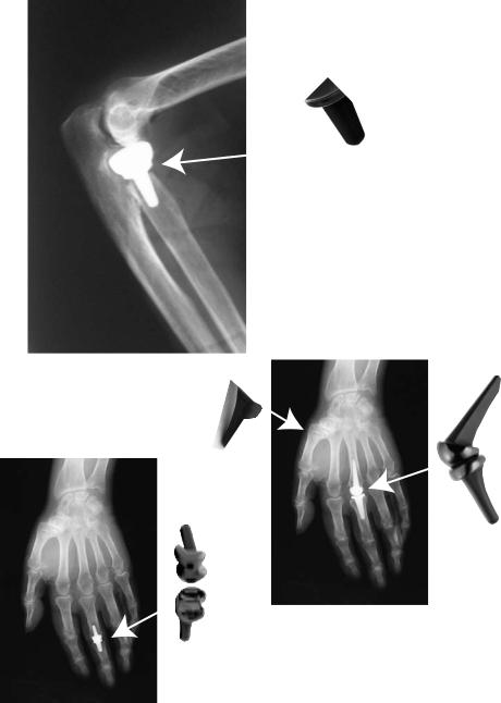
CMC
PIP
matrix in which the carbon fibers are included and the geometry and orientation of the fiber inclusions (3).
Diamond-like carbon (DLC) coatings may find use as low friction, wear resistant surfaces for joint articulating surfaces in orthopedic implants (87,88). However, the coating thickness is limited to the micrometer level; the technology is still in development and ultimately may not be competitive with the newer ceramic joint replacement materials.
Buckyballs (fullerenes) and carbon nanotubes are cagelike structures that suggest use as a means to encapsulate and selectively deliver molecules to tissues. Because of their nanometer dimensions, fullerenes can potentially travel throughout the body. Some current biomedical applications under study involve functionalizing fullerenes with
BIOMATERIALS: CARBON |
305 |
RH
MCP
Figure 7. Ascension Orthopedics small joint PyC prostheses for finger joints.
a number of substances including DNA and peptides that can specifically target, mark, or interfere with active sites on enzymes and perhaps inhibit virulent organisms such as the human immunodeficiency virus (89–93). They may also be used to selectively block ion channels on membranes (94). Fullerenes are synthesized by CVD and PVD techniques and can have a variety of novel properties depending on preparation. Currently, there are production difficulties with separation and isolation of fullerenes from the rest of soot-like materials that can occur during synthesis. However, bulk separation methods have been developed and some commercial sources have appeared. See http:// www. chemistry.wustl.edu/ edudev/Fullerene/fullerene. html#index and http://www.pa.msu.edu/cmp/csc/nanotube. html. There is a wealth of information available on
306 BIOMATERIALS: CARBON
the Internet that is readily accessed. Medical applications of fullerenes are currently a topic of intense interest and activity and hold much promise for future developments.
CONCLUSION
Uses of carbon as a biomaterial range from burnt toast, as mother’s first aid remedy for suspected poisoning, to the newly discovered fullerene nanomaterials as a possible means to treat disease on a molecular level. The most successful and widespread medical applications have been the use of activated carbons for detoxification and the use of the General Atomics family of isotropic, fluidized-bed, pyrolytic carbons for structural components of long-term critical implants. However, the successful biomedical application of carbon requires an understanding that carbon is a spectrum of materials with wide variations in structure and properties. While a given carbon may be biocompatible, it may not have the mechanical and physical properties needed for the intended application.
As for the future, additional applications of the biomedical PyC materials to orthopedic applications in larger joints and in the spine can be expected, especially if successful long-term hemiarthroplasty devices can be demonstrated. New cardiovascular devices can be expected, such as components for venous shunts and venous valves. The most exciting new developments will probably occur in nanotechnology with the creation of functional, fullerene type, materials, devices, and systems through control of matter at the scale of 1–100 nm, and the exploitation of novel properties and phenomena at the same scale.
BIBLIOGRAPHY
Cited References
1.Pauling L. College Chemistry. San Francisco: W.H. Freeman; 1964.
2.Pierson HO. Handbook of Carbon, Graphite, Diamond and Fullerenes. Park Ridge, New Jersey: Noyes Publications; 1993.
3.Haubold AD, More RB, Bokros JC. Carbons. In: Black J, Hastings G, editors. Handbook of Biomaterial Properties. London: Chapman & Hall; 1998. p 464–477.
4.Janvier G, Baquey C, Roth C, Benillan N, Belisle S, Hardy J. Extracorporeal circulation, hemocompatibility, and biomaterials. Ann Thorac Surg 1996;62:1926–1934.
5.Morrison RT, Boyd RN. Organic Chemistry. Boston: Allyn and Bacon; 1974.
6.Properties and Characteristics of Graphite for the Semiconductor Industry. In: Sheppard RG, Mathes DM, Bray DJ, editors. Decatur, TX: POCO Graphite, Inc.; November 2001. Can be downloaded from http://www.poco.com.
7.Spain IL. Electronic Transport Properties of Graphite, Carbons, and Related Materials. Chem Phys Carbon 1981; 16:119
8.Kroto HW, Heath JR, O’Brien SC, Curl RF, Smalley RE. C60: Buckminsterfullerene. Nature (London) 1985;318(6042): 162–163.
9.Haddon RC, Brus LE, Raghavachari K. Electronic Structure
and Bonding in Icosahedral C60. Chem Phys Lett 1986; 125:459.
10.O’Brien SC, Heath JR, Curl RF, Smalley RE. Photophysics of Buckminsterfullerene and Other Carbon Cluster Ions. J Chem Phys 1988;88:220.
11.Heath JR, O’Brien SC, Zhang Q, Liu Y, Curl RF, Kroto HW, Tittel FK, Smalley RE. Lanthanum Complexes of Spheroidal Carbon Shells. J Am Chem Soc 1985;107:7779–7780.
12.Chai Y, Guo T, Jin C, Haufler RE, Chibante LPF, Fure J, Wang L, Alford JM, Smalley RE. Fullerenes with Metals Inside. J Phys Chem 1991;95:7564
13.Heiney PA, Fischer JE, McGhie AR, Romanow WJ, Denenstein AM, McCauley JP, Jr., Smith AB, III, Cox DE. Orienta-
tional Ordering Transition in Solid C60. Phys Rev Lett 1991;66:2911.
14.Haddon RC, Hebard AF, Rosseinsky MJ, Murphy DW, Duclos SJ, Lyons KB, Miller B, Rosamilia JM, Fleming RM, Kortan AR, Glarum SH, Makhija AV, Muller AJ, Eick RH, Zahurak SM, Tycko R, Dabbagh G, Thiel FA. Conducting Films of C60 and C70 by Alkali-Metal Doping. Nature (London) 1991; 350:320.
15.Bleeke JR, Frey RF. Fullerene Science Module. St. Louis, MO: Department of Chemistry, Washington University; Available at http://www.chemistry.wustl.edu /edudev/Fullerene/fullerene.html.
16.Iijima S. Helical microtubules of graphitic carbon. Nature (London) 1991;354:56.
17.Tomanek D, of the University of Michigan, nanotube web page http://www.pa.msu.edu/cmp/csc/nanotube.html.
18.Jenkins GM, Kawamura K. Polymeric Carbons–Carbon Fibers, Glass and Char. Cambridge: Cambridge University Press; 1976.
19.Bokros JC. Deposition, Structure and Properties of Pyrolytic Carbon. In: Walker PL, editor. Chemistry and Physics of Carbon. Volume 5, New York: Marcel Dekker, Inc.; 1969. p 1–118.
20.Ely JL, Emken MR, Accuntius JA, Wilde DS, Haubold AD, More RB, Bokros JC. Pure Pyrolytic Carbon: Preparation and Properties of a New Material, On-X Carbon for Mechanical Heart Valve Prostheses. J Heart Valve Dis 1998;7:626–632.
21.Cooney DO. Activated Charcoal: Antidotal and Other Medical Uses. New York: Marcel Dekker; 1980.
22.Baker FS, Miller CE, Repik AJ, Tolles ED. Activated Carbon, in Kirk–Othmer. Encyc Chem Technol 1992;4:1015–1037.
23.Puri Balwant Rai. Chemsiorbed oxygen evolved as carbon dioxide and its influence on surface reactivity of carbons. Carbon 1966;4:391–400.
24.Cheremishoff NP, Moressi AC. Carbon adsorption applications. In: Cheremisinoff NP, Ellerbusch F, editors. Carbon Adsorption Handbook. Ann Arbor: Ann Arbor Science; 1978.
25.Pradhan BK, Sandle NK. Effect of different oxidizing agent treatments on the surface properties of activated carbons. Carbon 1999;37:1323–1332.
26.McQreey RL. Carbon electrodes: structural effects on electron transport kinetics. In: Bard AJ, editor. Electroanalytical Chemistry. New York: Dekker; 1991.
27.See Matweb.com for a variety of properties for engineering materials.
28.Diefendorf RJ, Stover ER. Pyrolytic Graphites. . .How structure affects properties. Metals Prog 1962;8 (May): 103–108.
29.Schoen FJ. Carbons in Heart Valve Prostheses: Foundations and clinical Performance. In: Zycher M, editor. Biocompatible Polymers, Metals and Composites. Lancaster PA: Technomic; 1983. p 240–261.
30.Bokros J. Carbon biomedical devices. Carbon 1977;15:355–371.
31.Haubold AD, Shim HS, Bokros JC. Carbon in Medical Devices. In: Williams DF, editor. Biocompatibility of Clinical Implant Materials. Volume 2, Boca Raton, FL: CRC Press; 1981. p 3–42.
32.More RB, Haubold AD, Bokros JC. Pyrolytic Carbon for LongTerm Medical Implants. In: Ratner B, Hoffman A, Schoen F, Lemons J, editors. Biomaterials Science: An Introduction to Materials in Medicine. 2nd ed. Academic Press; 2004.
33.More RB, Sines G, Ma L, Bokros JC. Pyrolytic Carbon. Encyclopedia of Biomaterials and Biomedical Engineering. Marcel Dekker; 2004.
34.Baier RE, Gott VL, Feruse A. Surface Chemical Evaluation of Thromboresistant Materials Before and After Venous Implantation. Trans Am Soc Artif Intern Organs 1970; 16:50–57.
35.Lee RG, Kim SW. Adsorption of Proteins onto Hydrophobic Polymer Surfaces: Adsorption Isotherms and Kinetics. J Biomed Mater Res 1974;8:251.
36.Nyilas E, Chiu TH. Artificial Surface/Sorbed Protein Structure/Hemocompatibility Correlations. Artif Organs 1978;2 (Suppl): 56–62.
37.Salzman EW, Lindon J, Baier D, Merril EW. Surface-Induced Platelet Adhesion, Aggregation and Release. Ann NY Acad Sci 1977;283:114.
38.Feng L, Andrade JD. Protein Adsorption on Low-Tempera- ture Isotropic Carbon: I Protein Conformational Change Probed by Differential Sacnning Calorimetry. J Biomed Mater Res 1994;28:735–743.
39.Chinn JA, Phillips RE, Lew KR, Horbett Fibrinogen and Albumin Adsorption to Pyrolite Carbon. Trans Soc Biomater 1994;17:250.
40.Guglielmotti MB, Renou S, Cabrini RL. A histomorphometric study of tissue interface by laminar implant test in rats. Int J Oral Maxillofac Implants 1999;14:565–570.
41.Santavirta S, Takagi M, Gomez-Barrena E, Nevalainen J, Lassus J, Salo J, Konttinen YT. Studies of host response to orthopedic implants and biomaterials. J Long Term Eff Med Implants 1999;9:67–76.
42.Hill JB, Horres CR. The BD Hemodetoxifier: Particulate release and its significance. In: Chang TMS, editor. Artificial Kidney, Artificial Liver and Artificial Cells. New York: Plenum Press; 1978. p 199–207.
43.Williams DF. The Williams’ Dictionary of Biomaterials. United Kingdom: Liverpool University Press; 1999.
44.Fettel BE, Johnston DR, Morris PE. Accelerated life testing of prosthetic heart valves. Med Inst 1980;14(3): 161–164.
45.Bensen J. Pre-Survey on the Biomedical Applications of Carbon. 1969. North American Rockwell Corporation Report R-7855.
46.Ford X. Clinical Toxicology. 1st ed., W. B. Saunders Company; 2001.
47.Roberts X. Clinical Procedures in Emergency Medicine. 3rd ed., W. B. Saunders Company; 1998.
48.LaGrange LD, Gott VL, Bokros JC, Ramos MD. Compatibility of Carbon and Blood. In: Hegyeli RJ, editor. Artificial Heart Program Conference Proceedings. Washington, DC: US Government Printing Office; 1969. Chapt. 5. p 47–58.
49.Sadeghi H. Dysfonctions des prostheses valvulaires cardaques et leur traitment chirgical. Schwiez Med Wschr 1987; 117:1665–1670.
50.Kaae JL. The mechanism of deposition of pyrolytic carbon. Carbon 1985;23(6): 665–667.
51.Kaae JL, Wall DR. Microstructural Characterization of Pyrolytic Carbon for Heart Valves. Cells Mater 1996;6(4): 281–290.
52.Ma L, Sines G. High resolution structural studies of a pyrolytic carbon used in medical applications. Carbon 2002;40:451–454.
53.Akins RJ, Bokros JC. The Deposition of Pure and Alloyed Isotropic Carbons and Steady State Fluidized Beds. Carbon 1974;12:439–452.
54.Reilly DT, Burstein AH, Frankel VH. The Elastic Modulus for Bone. J Biomech 1974;7:271.
BIOMATERIALS: CARBON |
307 |
55.Reilly DT, Burstein AH. The Mechanical Properties of Bone. J Bone Jt Surg Am 1974;56:1001.
56.De Salvo G. Theory and Structural Design Applications of Weibull Statistics. 1970. WANL-TME-2688, Westinghouse Electric Corporation.
57.More RB, Kepner JL, Strzepa P. Hertzian Fracture in Pyrolite Carbon. In: Ducheyne P, Christiansen D, editors. Bioceramics. Volume 6, Oxford: Butterworth-Heinemann Ltd; 1993. p 225–228.
58.Gilpin CB, Haubold AD, Ely JL. Fatigue Crack Growth and Fracture of Pyrolytic Carbon Composites. In: Ducheyne P, Christiansen D, editors. Bioceramics. Volume 6, Oxford: Butterworth-Heinemann Ltd; 1993. p 217–223.
59.Ma L, Sines G. Fatigue of Isotropic Pyrolytic Carbon Used in Mechanical Heart Valves. J Heart Valve Dis 1996;5(Suppl.I): S59–S64.
60.Ma L, Sines G. Unalloyed Pyrolytic Carbon for Implanted Heart Valves. J Heart Valve Dis 1999;8(5): 578–585.
61.Ma L, Sines G. Fatigue Behavior of Pyrolytic Carbon. J Biomed Mat Res 2000;51:61–68.
62.Ritchie RO, Dauskardt RH, Yu W, Brendzel AM. Cyclic Fatigue-crack Propagation, Stress Corrosion and Fracture Toughness Behavior in Pyrolite Carbon Coated Graphite for Prosthetic Heart Valve Applications. J Biomed Mat Res 1990;24:189–206.
63.Beavan LA, James DW, Kepner JL. Evaluation of Fatigue in Pyrolite Carbon. In: Ducheyne P, Christiansen D, editors. Bioceramics. Volume 6, Oxford: Butterworth-Heinemann Ltd; 1993. p 205–210.
64.Bokros JC, Haubold AD, Akins RJ, Campbell LA, Griffin CD, Lane E. The durability of mechanical heart valves replacements: past experience and current trends. In: Bodnar E, Frater RWM, editors. Replacement Cardiac Valves. New York: Pergamon Press; 1991. p 21–47.
65.Haubold AD. On the Durability of Pyrolytic Carbon In Vivo. Med Prog Through Technol 1994;20:201–208.
66.Kelpetko V, Moritz A, Mlczoch J, Schurawitzki H, Domanig E, Wolner E. Leaflet Fracture in Edwards-Duromedics Bileaflet Valves. J Thorac Cardiovasc Surg 1989;97: 90–94.
67.Kafesjian R, Howanec M, Ward GD, Diep L, Wagstaff L, Rhee R. Cavitation Damage of Pyrolytic Carbon in Mechanical Heart Valves. J Heart Valve Dis 1994;3(Suppl I): S2–S7.
68.Richard G, Cao H. Structural failure of Pyrolytic Carbon Heart Valves. J Heart Valve Dis 1996;5(Suppl I): S79–S85.
69.Shim HS, Schoen FJ. The wear resistance of pure and siliconalloyed isotropic carbons. Biomater Med Dev Art Org 1974;2(2): 103–118.
70.Shim HS. The wear of titanium alloy, and UHMW polyethylene caused by LTI carbon and Stellite 21. J Bioengr 1977;1:223–229.
71.More RB, Silver MD. Pyrolytic Carbon Prosthetic Heart Valve Occluder Wear: In Vivo vs. In Vitro Results for the Bjo¨rk-Shiley Prosthesis. J Appl Biomater 1990;1:267–278.
72.More RB. An Examination of Two Retrieved Long-Term Human Implant Bjork-Shiley Valves. Med Prog Technol 1994;20:195–200.
73.More RB, Haubold AD, Silver MD. Pyrolytic Carbon Wear in Retrieved Mechanical Heart Valve Prosthesis Implants. 25th Annual Meeting of the Society for Biomaterials, 1999. p 553.
74.More RB, Chang BC, Hong YS, Cao BK, Butany J, Wear Analysis of Retrieved Mitral Bileaflet Mechanical Heart Valve Prostheses, Presented to the Society for Heart Valve Disease, 1st Biennial Symposium, London; June 2001.
75.More RB, Haubold AD, Silver MD. Pyrolytic Carbon Wear in Retrieved Mechanical Heart Valve Prosthesis Implants. 25th Annual Meeting of the Society for Biomaterials, 1999. p 553.