

- •VOLUME 1
- •CONTRIBUTOR LIST
- •PREFACE
- •LIST OF ARTICLES
- •ABBREVIATIONS AND ACRONYMS
- •CONVERSION FACTORS AND UNIT SYMBOLS
- •ABLATION.
- •ABSORBABLE BIOMATERIALS.
- •ACRYLIC BONE CEMENT.
- •ACTINOTHERAPY.
- •ADOPTIVE IMMUNOTHERAPY.
- •AFFINITY CHROMATOGRAPHY.
- •ALLOYS, SHAPE MEMORY
- •AMBULATORY MONITORING
- •ANALYTICAL METHODS, AUTOMATED
- •ANALYZER, OXYGEN.
- •ANESTHESIA MACHINES
- •ANESTHESIA MONITORING.
- •ANESTHESIA, COMPUTERS IN
- •ANGER CAMERA
- •ANGIOPLASTY.
- •ANORECTAL MANOMETRY
- •ANTIBODIES, MONOCLONAL.
- •APNEA DETECTION.
- •ARRHYTHMIA, TREATMENT.
- •ARRHYTHMIA ANALYSIS, AUTOMATED
- •ARTERIAL TONOMETRY.
- •ARTIFICIAL BLOOD.
- •ARTIFICIAL HEART.
- •ARTIFICIAL HEART VALVE.
- •ARTIFICIAL HIP JOINTS.
- •ARTIFICIAL LARYNX.
- •ARTIFICIAL PANCREAS.
- •ARTERIES, ELASTIC PROPERTIES OF
- •ASSISTIVE DEVICES FOR THE DISABLED.
- •ATOMIC ABSORPTION SPECTROMETRY.
- •AUDIOMETRY
- •BACTERIAL DETECTION SYSTEMS.
- •BALLOON PUMP.
- •BANKED BLOOD.
- •BAROTRAUMA.
- •BARRIER CONTRACEPTIVE DEVICES.
- •BIOCERAMICS.
- •BIOCOMPATIBILITY OF MATERIALS
- •BIOELECTRODES
- •BIOFEEDBACK
- •BIOHEAT TRANSFER
- •BIOIMPEDANCE IN CARDIOVASCULAR MEDICINE
- •BIOINFORMATICS
- •BIOLOGIC THERAPY.
- •BIOMAGNETISM
- •BIOMATERIALS, ABSORBABLE
- •BIOMATERIALS: AN OVERVIEW
- •BIOMATERIALS: BIOCERAMICS
- •BIOMATERIALS: CARBON
- •BIOMATERIALS CORROSION AND WEAR OF
- •BIOMATERIALS FOR DENTISTRY
- •BIOMATERIALS, POLYMERS
- •BIOMATERIALS, SURFACE PROPERTIES OF
- •BIOMATERIALS, TESTING AND STRUCTURAL PROPERTIES OF
- •BIOMATERIALS: TISSUE-ENGINEERING AND SCAFFOLDS
- •BIOMECHANICS OF EXERCISE FITNESS
- •BIOMECHANICS OF JOINTS.
- •BIOMECHANICS OF SCOLIOSIS.
- •BIOMECHANICS OF SKIN.
- •BIOMECHANICS OF THE HUMAN SPINE.
- •BIOMECHANICS OF TOOTH AND JAW.
- •BIOMEDICAL ENGINEERING EDUCATION
- •BIOSURFACE ENGINEERING
- •BIOSENSORS.
- •BIOTELEMETRY
- •BIRTH CONTROL.
- •BLEEDING, GASTROINTESTINAL.
- •BLADDER DYSFUNCTION, NEUROSTIMULATION OF
- •BLIND AND VISUALLY IMPAIRED, ASSISTIVE TECHNOLOGY FOR
- •BLOOD BANKING.
- •BLOOD CELL COUNTERS.
- •BLOOD COLLECTION AND PROCESSING
- •BLOOD FLOW.
- •BLOOD GAS MEASUREMENTS
- •BLOOD PRESSURE MEASUREMENT
- •BLOOD PRESSURE, AUTOMATIC CONTROL OF
- •BLOOD RHEOLOGY
- •BLOOD, ARTIFICIAL
- •BONDING, ENAMEL.
- •BONE AND TEETH, PROPERTIES OF
- •BONE CEMENT, ACRYLIC
- •BONE DENSITY MEASUREMENT
- •BORON NEUTRON CAPTURE THERAPY
- •BRACHYTHERAPY, HIGH DOSAGE RATE
- •BRACHYTHERAPY, INTRAVASCULAR
- •BRAIN ELECTRICAL ACTIVITY.
- •BURN WOUND COVERINGS.
- •BYPASS, CORONARY.
- •BYPASS, CARDIOPULMONARY.
12.Nath R, Anderson LL, Meli JA, et al.Code of practice for brachytherapy physics: AAPM Radiation Therapy Committee Task Group No. 56. Med Phys 1997;24:1557–1598.
13.Thomadsen BR. Achieving Quality in Brachytherapy. Bristol: Institute of Physics Press; 1999.
14.Rivard MJ, Kirk BL, Stapleford LJ, Wazer DE. A comparison
of the expected costs of high dose rate brachytherapy using 252Cf versus 192Ir. Appl Radiat Isot 2004;61:1211–1216.
See also BRACHYTHERAPY, INTRAVASCULAR; HYPERTHERMIA, INTERSTITIAL;
PROSTATE SEED IMPLANTS; RADIATION DOSIMETRY FOR ONCOLOGY.
BRACHYTHERAPY, INTRAVASCULAR
FIRAS MOURTADA
MD Anderson Cancer Center
Houston, Texas
INTRODUCTION
Intravascular brachytherapy (IVB) is a novel treatment modality that delivers ionizing radiation to a coronary artery to prevent renarrowing, that is, restenosis caused by stent placement within the artery. The term brachy is the Greek word for near since the radioactive source is placed inside or near the target cells. In general, the field of brachytherapy has been practiced for decades in the field of radiation oncology for treatment of intracavitary (vagina, bronchus, esophagus, rectum, nasopharynx, etc.) and interstitial (muscle sarcoma, prostate, breast, etc.) cancers. As a subspecialty, IVB is relatively new where most of its development took place in the 1990s. Ionizing radiation describes both electromagnetic (g rays, X rays) and particulate (neutrons, beta, and alpha particles) of sufficient energy to remove electrons from the target atom (thus ionizing). Unlike conventional brachytherapy where the target is mostly centimeters away from the source, IVB targets the adventitia of the vessel wall, located within 1–5 mm from the radioactive source. To obtain accurate dosimetry data in such close range is a challenge. The scope of this article is on the delivery devices for IVB and tools needed to assess the dosimetric properties of such brachytherapy devices. (Dosimetry is a subspecialty of radiation physics that deals with the measurement of the absorbed dose or dose rate resulting from the interaction of ionizing radiation with matter.) Such techniques are useful and can be applied in other future applications that require delivery of ionizing radiation to a target within a few millimeters from a radioactive source.
Mechanisms of Restenosis
A diseased coronary vessel is mainly caused by atherosclerotic plaque formation containing mostly cholesterol and lipids. This condition can lead to a heart attack and chest pain (angina) where the blood flood within the lumen is compromised. Coronary artery bypass surgery (CABG) is the traditional method to alleviate this condition. In the last few decades, minimally invasive procedures have been developed in a field known as Interventional Cardiology.
BRACHYTHERAPY, INTRAVASCULAR |
601 |
Percutaneous transluminal coronary angioplasty (PTCA), first performed by Gruentzig in 1977 (1); and endovascular prosthetic devices (stents), first performed by Dotter et al.
(2) and Cragg et al. (3) in 1983, are the most common devices used in interventional cardiology today. Charles Thomas Stent (1807–1885), an English dentist who lent his name to a tooth mould. Charles Dotter used the word ‘‘stent’’ in 1963 to name endoluminal scaffolding devices. However, these interventions have created a new problem, restenosis.
Restenosis is a wound healing process occurring directly at the angioplasty balloon or stent site. It is believed that three processes cause restenosis: elastic recoil, neointimal hyperplasia, and negative vascular remodeling. Elastic recoil, or vessel spasm, occurs in the healthy (plaque-free) portion of the vessel within minutes after balloon expansion (angioplasty balloon or stent-expanding balloon). Elastic recoil causes a luminal cross-sectional area reduction of 50%, but only for a short time after the procedure. The second component of restenosis is neointimal hyperplasia resulting in new tissue growth occupying the microcracks and rapture within the plaque mass, in some patients this process can be overcompensating, filling more tissue within the vessel lumen thus compromising blood flow. The blood vessel wall (any vessel larger than capillaries) has three major layers called tunica, the innermost layer is the intima followed by a middle concentric layer called the media where mostly the smooth muscle cells reside, and then the outer most layer called the adventitia. The adventitia contains a connective tissue with mainly collagen and myofibroblasts. Some controversy still remains as to which cells are responsible for neointimal hyperplasia, media smooth muscle cells, or myofibroblasts migrating from the adventitia. In IVB, the prescription dose should reach the tunica adventitia to insure full therapeutic benefit. The third component of restenosis is negative remodeling. The term negative remodeling refers to contraction of the arterial wall following an arterial injury inflicted by an interventional procedure occurring slowly over the first 3–9 months after the angioplasty. Negative remodeling is believed to play a major factor in restenosis after a PTCA intervention. However, the stent is a mechanical scaffolding device that prevents negative remodeling. Hence, in-stent restenosis appears to derive almost exclusively from neointimal hyperplasia, even more than seen in balloon angioplasty. Schwartz and Holmes (4) provide a detailed discussion on restenosis and remodeling. Hall et al. (5) present on the radiobiological response of vascular tissue to IVB. (5).
Epidemiology and Clinical Trials
Restenosis is a very likely event (within few months of the initial intervention) and has been a frustrating problem in interventional cardiology. For example, > 1 million people worldwide had percutaneous coronary interventions in 2001 and of these > 85% received a stent. Restenosis occurred in > 50% of the stented patients ( 425,000 patients worldwide), with the United States share of 150,000 patients.
Restenosis as measured using quantitative coronary angiography (QCA) is arbitrarily defined as a narrowing

602 |
BRACHYTHERAPY, INTRAVASCULAR |
|
|
|
|
|
|
|||
|
|
|
0 |
|
|
Stent Trials |
|
Radiotherapy Trials |
|
|
|
|
|
|
|
|
|
|
|||
|
|
|
|
|
|
|
|
|
|
|
|
|
|
|
|
|
|
|
|
|
|
|
|
Reduction |
−10 |
|
|
|
|
|
|
|
|
|
|
|
|
|
|
|
|||
|
|
|
|
|
|
|
|
|
|
|
|
|
|
−20 |
−23 |
|
|
|
|
|
|
|
|
|
|
|
|
|
|
|
||
|
|
Restenosis |
−30 |
|
−31 |
|
|
|
|
|
|
|
|
|
|
|
|
|
|||
|
|
−40 |
|
|
|
|
|
|
||
|
|
|
|
|
|
|
|
|||
|
|
|
|
|
|
|
|
|
||
Figure 1. Percent restenosis reduc- |
Percent |
−50 |
|
|
|
|
|
|
||
|
|
−57 |
|
|
|
|||||
tion reported in bare-metal stent |
−60 |
|
|
|
|
|
||||
|
|
|
|
|
|
|
|
|||
(STRESS and BENESTENT), and |
|
|
|
|
|
|
−66 |
−67 |
||
in intravascular brachytherapy clin- |
|
|
|
|
|
|
||||
ical trials Gamma I (192Ir), START |
|
−70 |
|
|
|
|
|
|
||
(90Sr/90Y), and INHIBIT (32P). |
|
STRESS |
BENESTENT |
GAMMA I |
START |
INHIBIT |
||||
of the vessel lumen of at least 50% relative to the adjacent healthy vessel lumen ratio of minimum lumen diameter (MLD) to the reference lumen diameter (RLD). Mehran et al. (6) studied several risk factors from angiographic patterns of in-stent restenosis (ISR). The MLD, lesion length, and diabetes were found to be important factors predicting in-stent restenosis risk. Risk increased as a function of lesion length (10–40 mm) and decreased as a function of the MLD (2.5–4 mm diameter). Further, the ISR pattern is important where diffused restenosis has a larger risk those with a focal pattern.
The main complications of PTCA are acute vessel occlusion and late restenosis. Two important trials started in 1991, the North American STRESS (STent REStenosis Study) (7) and the European BENESTENT (BElgium Netherlands STENT trial) (8) using metal-bare stents (Palmaz-Schatz stent) transformed the practice of interventional cardiology. (Bare-metal stent is a term used here to make a distinction from the drug-coated stent briefly discussed in this article.) However, in-stent restenosis incidence of > 50% was still observed. The introduction of IVB in the 1990s revamped the hope to eradicate restenosis. Condado et al. (9) in 1997 conducted the first small human trial showing reduction in restenosis over a 5 year follow-up period; this study, however, had some dosimetric issues. Definite multicenter double-blinded randomized clinical trials for IVB for the indication of in-stent restenosis are the GAMMA I (10), the START (Strontium-90 Treatment of Angiographic Restenosis Trial) (11), and the INHIBIT (INtimal Hyperplasia Inhibition with Beta Instent restenosis Trial) (12). With over 5000 patients treated with IVB, this modality has recently proven its safety and efficacy. As shown in Fig. 1, IVB (GAMMA I, START, INHIBIT) clinical trials had about twofold reduction of in-stent restenosis than found from the STRESS and BENESTENT bare-metal stent versus. PTCA trials. Initial problems in the IVB trials, like edge failure due to geographic miss and increased incidence of later thrombosis, were quickly remedied by increasing the radioactive source length and prolonged use of antiplatlet therapy. Table 1 is a detailed summary of these IVB clinical trials. Many other
clinical IVB clinical trials were conducted using various isotopes, delivery system, and other clinical indications.
THEORY AND DETAILED DESCRIPTION OF IVB DEVICES
Based on the clinical trials discussed above, the Food and Drug Administration (FDA) granted a premarket approval (PMA) to three IVB devices. The Checkmate system (Cordis Corporation, a Johnson & Johnson Company, Miami Lakes, FL) using 192Ir and BetaCath system using 90Sr (Novoste Corp. Norcross, GA) were both approved on November 3, 2000. About 1 year later, the GALILEO Intravascular Radiotherapy System (Guidant Corp., Santa Clara, CA) using 32P was also approved by the FDA. All of these devices are classified as catheter-based radiation delivery systems using sealed radioactive sources. Catheter-based means the source in the form of a source wire or a train of seeds (ribbon) is placed inside a closed-tip lumen catheter. The catheter is first placed into the target vessel and the source wire or ribbon is delivered or afterloaded using manual or computer-based delivery systems. The radiation safety considerations for these devices have been greatly discussed in the literature (13,14).
Other irradiation techniques were also investigated, including inflation of dilatation balloon catheter with radioactive liquid or gas; insertion of miniature X-ray tubes; implantation of radioactive stents; and postangioplasty external beam irradiation. These techniques did not make it to the market due to variable reasons including suboptimal efficacy, safety, or practicality. Table 2 summarizes several other isotopes and delivery systems investigated for IVB applications. Tables 3 and 4 list a few radiation characteristics for important gamma and beta sources for IVB.
Cordis Checkmate System
Checkmate is indicated by the FDA for the delivery of therapeutic doses of gamma radiation for the purpose of reducing in-stent restenosis. The system is for use in the treatment of native coronary arteries (2.75–4.0 mm in

BRACHYTHERAPY, INTRAVASCULAR |
603 |
Table 1. Summary of Pivotal IVB Clinical Trial Used to Obtain FDA Approval for In-Stent Restenosis in Native Arteries Indication
|
|
|
|
|
Angiographic Restenosis |
|
|
TLR |
|
|
|
|
|
Patients, n |
|
|
|
|
|
Trial |
Target Lesion |
Source |
Dose, Gy |
Rad., % |
Placebo % |
|
Rad. % |
Placebo, % |
|
|
|
|
|
|
|
|
|
|
|
Gamma-1 |
In-stent |
192Ir ribbon |
8–30 |
252 |
22 |
50 (6 months) |
24 |
42 (9 months) |
|
|
(< 45 mm) |
|
|
|
|
|
|
|
|
START |
In-stent |
90Sr/90Y |
16–20 Gy |
476 |
14 |
41 (8 months) |
16 |
24 (8 months) |
|
|
(< 20 mm) |
Seed train |
at 2 mm |
|
|
|
|
|
|
INHIBIT |
In-stent |
32P wire |
20 Gy at |
332 |
16 |
48 (9 months) |
11 |
29 (9 months) |
|
|
(< 45 mm) |
|
1 mm into |
|
|
|
|
|
|
|
|
|
vessel wall |
|
|
|
|
|
|
|
|
|
|
|
|
|
|
|
|
diameter and lesions up to and including 45 mm in length) with in-stent restenosis following percutaneous revascularization using current interventional techniques. Outside of the FDA approved indication, Waksman et al. (15) also examined the effects of intravascular gamma radiation in patients with in-stent restenosis of saphenous-vein bypass grafts and found favorable results.
Radioactive Source Ribbon. The Checkmate catheterbased brachytherapy system uses 192Ir seeds that are preassembled in 6, 10, and 14 seed strand inside nylon ribbons (Best Medical International, Springfield, VA). Treatment lengths are 23, 39, and 55 mm for the 6-, 10-, and 14-seed
ribbons, respectively (16). Iridium-192 has an average energy of 370 keV and a half-life of 73.83 days. The 192Ir
radioactive metal (30% Ir, 70% Pt) is 3 mm long and 0.1 mm in diameter encapsulated within a 3 mm long 0.5 mm diameter stainless steel capsule. The seeds are placed
Table 2. Gamma and Beta Sources with Different Delivery Systems Investigated for Intravascular Brachytherapy Applications
Gamma Delivery Systems |
Beta Delivery Systems |
|
|
192Irseed train |
32P - wire, stent, balloon |
125I-stent |
90Sr/90Y - seed train |
103Pd-stent, wire |
90Y - wire |
131Cs-stent |
188W/188Re - wire, balloon-liquid |
99mTc-liposome–liquid |
186Re - balloon-liquid |
|
133Xe - balloon-gas |
|
48V - stent (positron)a |
|
62Cu - balloon-liquid |
|
106Ru/106Rh - wire |
|
144Ce/144Pr - wire |
|
68Ge/68Ga balloon-liquid (positron) |
inside a nylon ribbon with an interseed spacing of 1 mm. The overall ribbon length is 230 cm and the outer diameter is 0.76 mm (2.4 F). [1 French (F) ¼ 1/p mm.] At both distal and proximal edges of the seed strand, radiopaque markers are placed for visualization under X rays. A nonradioactive dummy ribbon is preloaded inside the delivery catheter to provide reinforcement during shipping and to improve maneuverability during initial positioning of the catheter across the target lesion. The dummy ribbon has the same length and configuration of the radioactive source ribbon to aid in IVB therapy planning during the procedure. A source lumen plug is used to prevent the movement of the dummy ribbon inside the Checkmate delivery catheter during initial catheter placement via the femoral artery. Dosimetry characterization of the Checkmate source ribbon are discussed in the literature (17).
Delivery Catheter. This is a single lumen catheter with a distal rapid exchange tip and a closed-ended source lumen for isolation from patient blood contact. Both the radioactive source and the nonradioactive dummy ribbon use this lumen to reach the target. A single radiopaque marker at the distal end of the source lumen is to aid in catheter placement under fluoroscopy. A guidewire is used to guide the catheter along the tortuous pathway into the coronary artery. The guidewire exits the catheter 4 mm from the distal tip of the catheter. The overall length of the Checkmate catheter is 230 cm with a usable length of 145 cm. At the distal portion of the catheter, the outer diameter is 3.7 F (0.049 in.), which is deliverable with 7 F (mm) or larger guiding catheter.
Table 4. Maximum Energy and Half-Life of Important Beta Emitters Investigated for Intravascular Brachytherapy Applications
aA positron is an electron with a positive charge. |
|
|
|
|
|
|
|
|
||
|
|
|
Isotope |
Max Energy, keV |
T1/2 |
|||||
|
|
|
|
|
|
|||||
Table 3. Average |
Energy and |
Half-Life of |
Important |
|
32P |
|
1710 |
14.3 day |
||
90 |
90 |
|
2280 |
29.1 year |
||||||
Gamma Emitters |
Investigated |
for Intravascular Bra- |
|
Sr/ Y |
||||||
90 |
|
2280 |
64 h |
|||||||
chytherapy Applications |
|
|
|
|
|
Y |
|
|||
|
|
|
188 |
188 |
Re |
2120 |
69.4 day |
|||
|
|
|
|
|
|
W/ |
|
|||
Isotope |
Ave Energy, keV |
T1/2, day |
|
186Re |
|
1090 |
90.6 h |
|||
|
133Xe |
|
360 |
5.3 day |
||||||
|
|
|
|
|
|
|
||||
|
|
|
|
|
|
|||||
192Ir |
370 |
|
73.83 |
|
|
48V |
|
696 |
16 day |
|
125I |
28 |
|
59.4 |
|
|
62Cu |
|
2930 |
9.74 min |
|
103Pd |
21 |
|
16.97 |
|
106Ru/106Rh |
3540 |
371.6 day |
|||
131Cs |
30 |
|
9.69 |
|
|
144Ce/144Pr |
3000 |
284.9 day |
||
604 BRACHYTHERAPY, INTRAVASCULAR
Figure 2. Checkmate delivery device (Cordis Corporation, a Johnson & Johnson Company, Miami Lakes, FL) is mainly a lead shielded cylinder housing both the radioactive 192Ir source ribbon and dummy ribbon.
Delivery Device. As shown in Fig. 2, the Checkmate delivery device is mainly a lead shielded cylinder housing both the radioactive 192Ir source ribbon and the dummy ribbon. This is a simple device where the proximal end of the source ribbon (nonradioactive part) protrudes from the proximal end of the delivery device and is coiled when not in use. When in use, a threaded cap on the distal end of the delivery device is replaced with a luer connector, which is connected to the hub of the delivery catheter. The source ribbon is pushed forward by hand from the proximal end of the delivery device into the delivery catheter.
Dosimetry. The Checkmate IVB system dosimetry was initially based on intravascular ultrasound (IVUS). From these images, the distance from the center of the IVUS catheter to the outer edge of the media tissue, called the external elastic membrane (EEM) is measured. A minimum of three axial images is taken along the stented vessel segment to determine the maximum and minimum distance from the source to the EEM. The dwell time is then calculated to insure that 8 Gy is delivered to the EEM farthest from the source, provided that no > 30 Gy is delivered to the closest EEM. The IVUS-based dosimetry was later simplified to prescribe a fixed dose of 14 Gy at a distance of 2 mm from the centerline of the source. This provided a logistic solution to shorten procedure time and
to spread the use of this system since many of catheterization labs in the United States do not have IVUS image modality.
Novoste BetaCath
The first generation BetaCath is a 5.0 F (1.59 mm) system. This system was indicated by the FDA to deliver beta radiation to the site of successful percutaneous coronary intervention for the treatment of in-stent restenosis in native coronary arteries with discrete lesions of 20 mm in length using the 30 or 40 mm system and for longer lesions up to 40 mm using a longer source train (60 mm) in a reference vessel diameter ranging from 2.7 to 4.0 mm. The second generation BetaCath is a 3.5 F (1.17 mm) system, which has an equivalent radioactivity to the 5 F (1.59 mm) system, but is smaller in diameter and fits easily inside a (1.91 mm) guide catheter. This system is intended to deliver beta radiation.
The 3.5 F (1.17 mm) BetaCath system has three main components, the 90Sr source train, the b-Rail 3.5 F delivery catheter, and the 3.5 F delivery device.
Radioactive Source. Strontium-90/Yttrium-90 is a pure beta emitter with any energy spectrum with maximum energy of 2.27 MeV and an average of 0.934 MeV. The long half-life (29.1 years) simplifies treatment planning due to the almost unchanged dose rate of the device during the life cycle of the device (6 month). Each seed is 2.5 mm long and 0.38 mm in diameter for the 3.5 F system (0.64 mm seed diameter for the 5 8F system), manufactured by AEA Technology GmbH, Germany or BEBIG Isotopenund Medizintechnik GmbH, Berlin, Germany. The radioactive source train consists of a wire jacketed ‘‘train’’ of 12 (30 mm source train), 16 (40 mm source train), or 24 (60 mm source train). The jacketed design was a major improvement over the initial design to eliminate seed movement thus providing uniform dose distribution. A radiopaque mark is placed one each side of each source train to provide visualization under fluoroscopy. Dosimetry characterization of the BetaCath sources are discussed in the literature (18,19).
Delivery Catheter. Only details of the second-generation delivery catheter, b-Rail 3.5 F (1.17 mm), will be discussed. This is a closed-end catheter with a total length of 180 cm (Fig. 3). A longer catheter called b-Rail 3.5 F XL delivery catheter has an overall length of 267 cm if desired. The catheter has a guidewire exit port at 1 cm from the distal tip, that is, a rapid exchange design. This catheter accommodates all source train lengths (30, 40, or 60 mm) that reach a most distal radiopaque marker located inside the delivery catheter. The b-Rail delivery catheter is preloaded with an Indicator of Source Train (IST), this Novoste terminology is used for the nonradioactive dummy source to aid in the measurement and positioning of the delivery catheter to insure adequate radiation coverage. The IST includes two radiopaque markings to delineate 30, 40, and 40 mm source lengths. At the proximal end of the delivery catheter, a proprietary connector is provided to insure a secure connection to the delivery device described next.

BRACHYTHERAPY, INTRAVASCULAR |
605 |
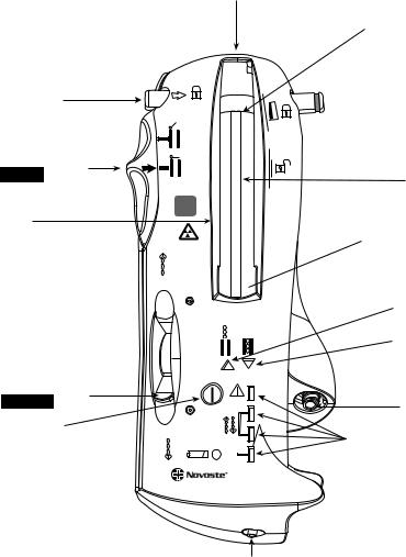
Delivery Device. This is a handheld battery-powered device used to store the radioactive source train (only one length). Hence, three separate delivery devices are needed to accommodate the 30, 40, and 60 mm source trains described above. The source train is sent into and returned from the delivery catheter using hydraulic pressure. To insure safe attachment of the delivery catheter, a connector lock latch is provided at the exit port of the delivery device. Several electronic pressure sensors are used to provide the operator with feedback on the pressure required using a saline-filled syringe to send, hold, or return the source train. Two source train position indicator lights (Green: In/Amber: Out), adjacent to the source chamber-viewing window (see Fig. 4). A fluid control lever controls the fluid flow and direction of the source train movement. A treatment counter tracks the number of procedures or test runs, a maximum of 125 transfers is allowed.
Dosimetry. The BetaCath IVB system dose prescription is the simplest out of the three systems discussed. The dose prescription is given relative to the source axis at 2 mm radial distance. The recommended dose is 18.4 Gy for a measured reference vessel diameter < 3.35 mm, but > 2.7 mm;
Figure 3. The b-Rail 3.5 F delivery catheter (Novoste, Norcross, GA) is a closed-end catheter with a total length of 180 cm. A longer catheter called b-Rail 3.5 F XL delivery catheter has an overall length of 267 cm is available. (Courtesy of Novoste Corporation.)
and 23 Gy for a diameter > 3.35 mm, but < 4.0 mm. Vessel diameters < 2.75 mm or > 4.0 mm can be treated with this system; however, this is considered an off-label use of the device as defined by the FDA. The appropriate source train length (30, 40, or 60 mm) is selected after measuring the injured length using angiography and adding a margin on the distal and proximal side of a minimum of 5 mm.
Guidant Galileo
This IVB system is the only computer-based device. The GALILEO Intravascular Radiotherapy System (Guidant Corp., Santa Clara, CA) consists of three main components: the GALILEO 32P Source Wire, the GALILEO Centering Catheter, and GALILEO Source Delivery Unit (SDU). The first generation product used a 27 mm long 32P source and spiral centering catheter. The second generation, called GALILEO III uses a 20 mm long 32P source, a trichannel centering catheter, and an automated high precision stepping algorithm.
The first generation GALILEO was indicated to deliver beta radiation to the site of successful percutaneous coronary intervention for the treatment of in-stent restenosis
606 BRACHYTHERAPY, INTRAVASCULAR
Proprietary connector receptacle
|
Distal radiopaque |
|
|
source train marker |
|
Proprietary connector lock |
|
|
latch (locked) |
|
|
|
Open |
|
Gate control switch |
Close |
|
in CLOSE position |
||
Jacketed |
||
|
||
|
source train |
|
|
60 |
|
Source |
mm |
|
|
||
chamber |
Proximal radiopaque |
|
|
||
|
source train marker |
Figure 4. The BetaCath 3.5 F system (Novoste, Norcross, GA) is a handheld battery-powered device used to store the radioactive source train (only one length of 30, 40, or 60 mm source trains). Source train transfer depends on hydraulic pressure. Several electronic pressure sensors are used to provide the operator with feedback on the pressure required using a saline-filled syringe to send, hold, or return the source train. (Courtesy of Novoste Corporation.)
Fluid control lever
in RETURN position
On/off button
Low battery indicator 
in native coronary arteries with discrete lesions 47 mm in reference vessel diameter 2.4–3.7 mm. The second generation GALILEO III system extended the indication to treat injured arterial length up to 52 mm.
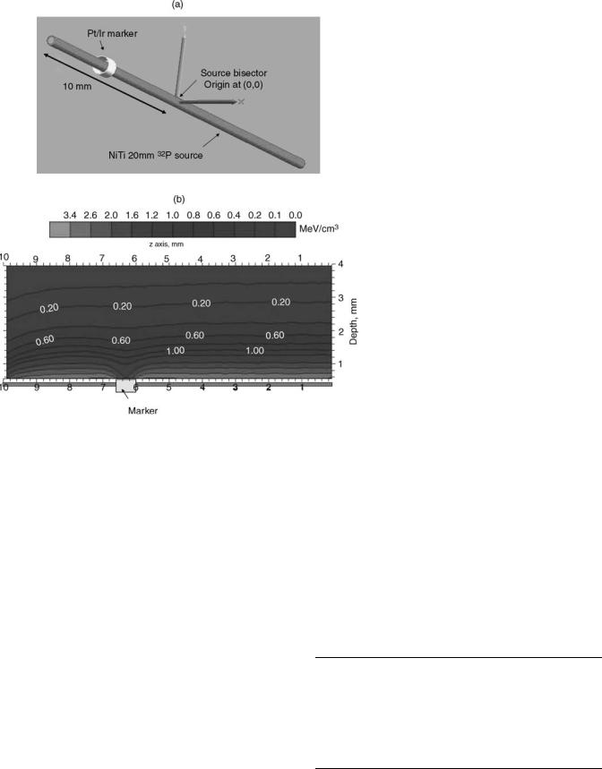
Radioactive Source. The active wire contains linear solid-form phosphorus 32 (32P) in ceramic glass fiber sealed in the distal end of a flexible nitinol (NiTi) hypotube, which is welded to a nitinol wire (total wire length is 2430 mm). The nominal active length is 27 mm (first generation system) 20 mm (second generation system). Both source wires have an outer diameter of 0.46 mm. Phosphorus-32 is a pure beta-emitting isotope with a maximum energy of 1.71 MeV, an average energy of 0.690 MeV, and a half-life of 14.28 days. The active wire can be used in multiple procedures for
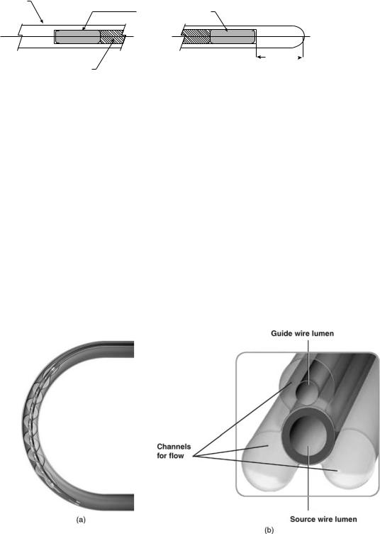
4 weeks (two half-lives). The active wire has two 1 mm tungsten X-ray markers, one proximal and one distal from the source, for visualization (see Fig. 5). A dummy source is used before the active wire is delivered to verify positioning, to check for kinks and catheter obstructions that could prevent the active wire from reaching the treatment site, and to achieve accurate positioning at the treatment site. Similar to the active wire, the dummy source also has two
SEND
|
Amber arrow |
Out In |
indicator light |
|
|
|
Green arrow |
|
indicator light |
|
Syringe luer |
Tx |
Pressure indicator lights |
RETURN |
|
BETA-CATHTM 3.5F |
|
SYSTEM |
|
Fluid collection bag luer
tungsten markers, making it visually identical to that of the active wire. Dosimetry characterization of the Galileo sources are discussed in the literature (20,21).
Delivery Catheter. This is a dual-lumen catheter with a spiral-shaped (first generation) or triloped balloon (second generation) to provide source centering within the lumen to improve dose homogeneity (see Fig. 6a and b). Such balloon profiles are designed to center the source within the lumen and to allow distal and side-branch perfusion during the dwell time that can take up to 10 min. This would make the procedure more tolerable for patients. The design of the second generation was found to provide better perfusion than the spiral design, in particular for the longer balloons to treat longer lesions. One lumen allows the automatic advancement of the source wire. At the proximal end of this lumen, a key connector attaches the delivery catheter to the delivery device. The key connector has a special code that reads using an optical sensor at the entry port to automatically determine the balloon length and the number of dwell positions based on the centering catheter used. The distal end of this lumen is closed to prevent contact of the source wire with the patient blood. The second lumen
|
|
|
|
|
|
|
|
|
|
|
|
|
|
|
|
|
|
|
|
BRACHYTHERAPY, INTRAVASCULAR |
607 |
|
NT Encapsulation |
|
|
|
|
|
|
|
|
|
|
|
|
|
Figure 5. Cross-section of the |
||||||||
0.46 mm |
|
|
TUNGSTEN MARKER |
|
|
|
|
|
|
|
|
|
|
32P source wire (Guidant Cor- |
||||||||
|
|
|
|
|
|
|
|
|
|
OD 0.27 mm |
|
|
|
|
|
|
|
|
|
|
poration, Santa Clara, CA) is |
|
|
|
|
|
|
|
|
|
|
|
LENGTH 1.00 MM |
|
|
|
|
|
|
|
|
|
|
shown. The radioactive core has |
|
|
|
|
|
|
|
|
|
|
|
|
|
|
|
|
|
|
|
|
|
|
a nominal length of 20 mm and 1 |
|
|
|
|
|
|
|
|
|
|
|
|
|
|
|
|
|
|
|
|
|
|
mm tungsten X-ray markers, one |
|
|
|
|
|
|
|
|
|
|
|
|
|
|
|
|
|
|
|
|
|
|
||
|
|
|
|
|
|
|
|
|
|
|
|
|
|
|
|
|
|
|
|
|
on each side of the core. All di- |
|
|
|
|
|
|
|
|
|
|
|
|
|
|
|
|
|
|
|
|
|
|
||
|
P32 Core |
|
|
|
|
|
|
|
|
|
|
|
|
1.00 mm |
mensions are in millimeters. |
|||||||
OD, 0.24 mm |
|
|
|
|
|
|
|
|
|
|
|
|
|
(Courtesy of Guidant Corpora- |
||||||||
LENGTH 20 mm |
|
|
|
|
|
|
|
|
|
|
|
|
|
tion: GALIELO system is no |
||||||||
|
|
|
|
|
|
|
|
|
|
|
|
|
|
|
|
|
|
|
|
|
longer manufactured or for sale.) |
|
allows inflation (recommended pressure is 4 atm) and deflation of the centering balloon. This lumen terminates in a luer-lock connector allowing the attachment of standard inflation devices. A third lumen is 5 mm long at the most distal tip of the catheter; this is used to place the delivery catheter over a standard 0.014 in. (0.36 mm) coronary guide wire using a Rapid Exchange approach. Radiopaque markers located at the distal and proximal end of the balloon allows proper placement of the delivery catheter under fluoroscopy. Proximal shaft markers are located at 95 and 105 cm to aid in gauging catheter position relative to the tip of a brachial or femoral guiding catheter, respectively. The triloped GALILEO III centering catheter is provided with a balloon diameter of 2.5, 3.0, and 3.5 mm and balloon lengths of 32 and 52 mm. (Balloon length is defined as the distance between radiopaque balloon markers and does not include balloon tapers that extend beyond these markers). The MLD determines the appropriate centering catheter balloon diameter to use in the
artery segment being treated (see Table 5). The lesion length determines the appropriate centering catheter length to use (see Table 6).
Delivery Device. The delivery device or the SDU has three main components: the head, base, and cartridge.
The front of the SDU head (Fig. 7) includes the touch screen monitor, status indicator lights, and housing for the cartridge. It also contains the manual retract wheel, the cartridge key port, the catheter key port and catheter eject button, and the red STOP button. On the back of the SDU head are the touch screen tilt lever, the swivel handle, and the system key port. The SDU head houses two motor drives—a primary motor and a battery-operated emergency retract motor. The emergency-retract motor works automatically if the primary motor fails to retract the active wire.
The SDU base provides a stable foundation for the SDU head and allows the unit to be transported easily.
Figure 6. (a) Galileo first generation spiral centering catheter (Guidant Corporation, Santa Clara, CA) is shown inside a 3 mm diameter curved lumen, balloon is inflated to 4 atm with saline to provide optimal source centering and distal blood perfusion (Courtesy of Guidant Corporation—GALIELO system is no longer manufactured or for sale.) (b) Cross-section of a Galileo second generation trilobed centering catheter (Guidant Corporation, Santa Clara, CA) is shown. Source lumen is central and the three lobes are inflated to 4 atm with saline to provide optimal source centering and distal blood perfusion. Note guide wire lumen inside one of the lobes. (Courtesy of Guidant Corporation—GALIELO system is no longer manufactured or for sale.)
608 BRACHYTHERAPY, INTRAVASCULAR
Table 5. Balloon Diameter Selection for the Guidant Galileo Centering Catheter as a Function of the Measured MLD
Balloon Diameter, mm |
|
MLD, mm |
|
|
|
2.5 |
|
2.25–2.75 |
3.0 |
|
2.75–3.25 |
3.5 |
|
3.25–3.7 |
|
||
Table 6. Balloon and Equivalent Source Length Selection |
||
|
|
|
Balloon Length, |
Injured Arterial |
Equivalent Source |
mm |
Length, mm |
Length, mm |
|
|
|
32 |
32 |
40 |
52 |
33–52 |
60 |
|
|
|
Components of the base include the head release, the handle bar, the emergency compartment, the wheels and wheel locks, and the power cord port. The emergency compartment contains the equipment necessary to handle an emergency, including the emergency safe, the emergency wire cutter, and the emergency tongs.
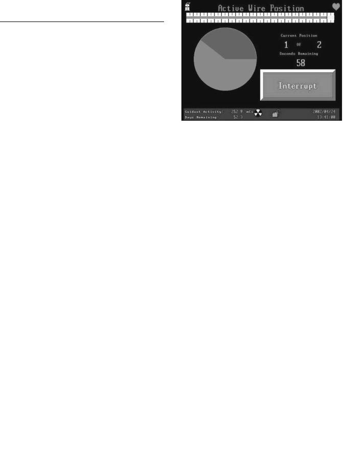
The cartridge, which is inserted into the SDU head, contains the active (32P source) wire, the dummy wire, and the operating software. It also contains the catheter key port, the tungsten safe, which shields the active wire when not in use, and the wire drive mechanisms. Figure 8 is an example of the GALILEO software screen of the countdown clock.
Figure 8. A screen shot of the Galileo software of the countdown clock for a treatment with two-source positions using the automatic source positioning system. (Courtesy of Guidant Corporation— GALIELO system is no longer manufactured or for sale.)
Dosimetry. Based on the measured minimal lumen diameter and lesion length via fluoroscopy, online QCA, or IVUS, a proper centering balloon size is chosen. Also the lumen diameter of the nondiseased vessel is measured immediately proximal and immediately distal to the treatment area. The average of these two diameters is the RLD. The GALILEO prescription point for radiation delivery is 1 mm beyond the RLD. The SDU automatically calculates the dwell time required to deliver the prescribed dose of radiation (20 Gy) at the prescription point. The GALILEO
Figure 7. A front view of the Galileo source delivery system. It includes the Touch Screen Monitor, Status Indicator Lights, and housing for the Cartridge. It also contains the Manual Retract Wheel, the Cartridge Key Port, the Catheter Key Port and Catheter Eject Button, and the red STOP Button. (Courtesy of Guidant Corporation–GALIELO system is no longer manufactured or for sale.)
BRACHYTHERAPY, INTRAVASCULAR |
609 |
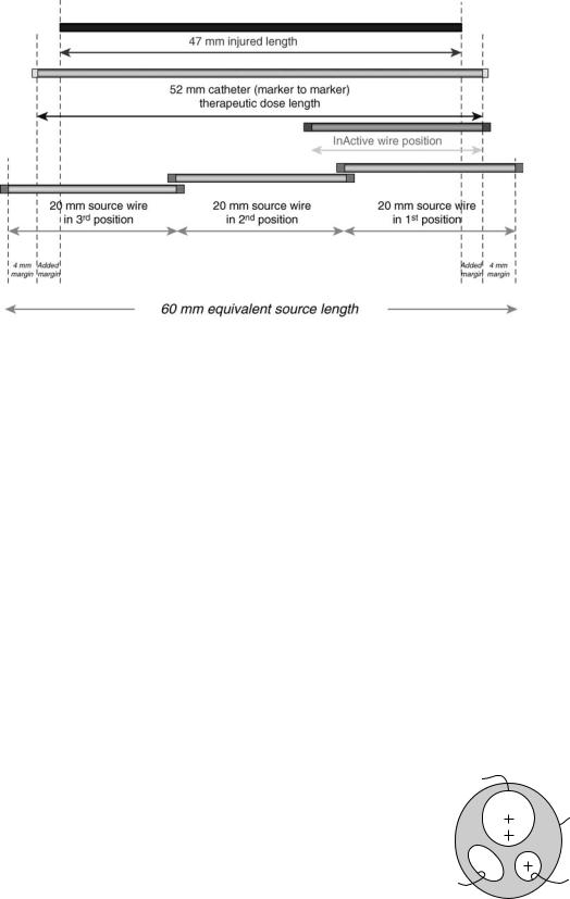
SDU automatically steps the 20 mm 32P source from most distal position to the most proximal position to yield an equivalent source length sufficient to cover the injured length with a minimal margin of 4 mm (Table 6). Equivalent source length (ESL) is defined as the total source length that will be result by stepping the 20 mm active source in tandem, either in two dwell positions (40 mm equivalent source length) or in three dwell positions (60 mm equivalent source length). Figure 9 is an example of 60 mm ESL to treat a 47 mm lesion, note the added margin of 2.5 mm to the minimal margin of 4mm to provide adequate radiation coverage.
DESIGN CONSIDERATION FOR IVB DEVICES AND DOSIMETRY
For beta emitters (90Sr/90Y, 32P) used currently in intravascular brachytherapy, the prescribed dose is greatly influenced by several perturbation factors. These perturbation factors are divided into two categories; the first is applicator dependent and the second is patient anatomy dependent. Important applicator perturbation factors include the placement of a guidewire during irradiation, the source lumen eccentricity within the applicator and centering capability with the vessel lumen, use of contrast, X-ray markers, and source stepping precision (if injured lengths longer than the source radioactive length are treated). Patient perturbation factors include vessel anatomy (size, curvature, and cross-section eccentricity), plaque morphology (composition, density, and spatial distribution), and stent type. High energy gamma emitters like) 192Ir (J&J Checkmate system) are influenced by such factors as well, but with almost negligible magnitudes (22), hence the next discussion will focus on the does distributions perturbation of the beta sources only.
Applicator Dependent Perturbations
The applicator dependent factors discussed in this report are specific for two commercially available IVB beta source
Figure 9. An example of 60 mm equivalent source length resulting from stepping twice a 20 mm 32P source to treat a 47 mm lesion. Note the added margin of 2.5 mm to the minimal margin of 4 mm to provide adequate radiation coverage.
systems, that is, Novoste (90Sr/90Y) and Guidant (32P) systems. Five factors are discussed and considered most important, but are not inclusive, (1) guidewire, (2) source lumen eccentricity within the applicator and centering capability within the vessel lumen, (3) use of contrast, (4) X-ray markers, and (5) source stepping precision (manual vs. automatic).
Guide Wire Perturbation. The guide wire (GW) is used to navigate through the cardiovascular arteries during common interventional procedures, such as balloon angioplasty, stenting, and IVB. Commonly used guide wires are made of stainless steel and have a solid cross-section with diameter of 0.014 in. (0.36 mm). Several authors have reported on the dose perturbation due to the guide wire in IVB (23–25). Figure 6b depicts the cross-section of 3.0 mm GIII centring catheter with a 0.014 in. (0.36 mm) guide wire inside the upper lope. The distance from the center of the GW and source axis is not fixed in this design and the GW location can vary (shown at closest distance from the source lumen center). Also Fig. 10 depicts the location of the guide wire inside the 5 Fr BetaCath catheter. Shih et al. (24) provides a detailed study on dose perturbation as a function of the GW position relative to the source axis. A dose perturbation
Source
β cathTM 5F Catheter
Return |
Guide wire |
fluid |
|
Figure 10. Cross-section of the BetaCath 5 F delivery catheter. Note the location of the guide wore lumen relative to the source lumen. (Courtesy of Novoste Corporation.)

610 BRACHYTHERAPY, INTRAVASCULAR
factor (DPF), defined as the ratio of the doses with and without the presence of a guidewire was introduced to quantify the effects.100 The authors reported a DPF of up to 70% behind a GW for the beta sources. The dose reduction for the beta sources was found to be dependent on the guidewire location. For example, the dose reduction was 10% higher for a stainless steel guidewire located at 0.5 mm than that for the guidewire at 2 mm from the central axis of the source. The portion of the target volume affected (shadowed) dosimetrically by the guidewire was reduced when the guidewire was positioned farther away from the source. The shadow volume (in which the dose reduction occurs) can be reduced by up to 45% as the guidewire is moved away from the source axis from 0.5 to 2 mm.
Fluhs et al. (25) measured the GW [0.014 in. (0.3556 mm), stainless steel] perturbation using a plastic scintillator. The authors pointed that the insertion of a GW into the catheter close to the beta source causes a large angular asymmetry of the radiation emission. For a guide wire positioned eccentrically to the catheter the dose reduction is dominantly limited to a region of some 208 around the angle defined by catheter centerline and guide wire. At the catheter surface the maximal dose reduction in this region was found to be (30 2%, DPF ¼ 10%). At the typical dose prescription depth of 2 mm from the source axis the shielding effect decreased to (24 2%) (or DPF ¼ 76%). This value is remarkably larger than the dose reduction caused by any typical stent design.
Source Lumen Eccentricity. Sehgal et al. (26) reports on the dosimetric consequences of source centering (eccentricity) within the arterial lumen as one potentially important factor for the uniform delivery of dose to the arterial tissue. In this study, they have examined the effect of source centering on the resulting dose to the arterial wall from clinical intravascular brachytherapy sources containing 32P and 90Sr/90Y. Monte Carlo simulations using the MCNP code (described in Advanced Topics section below) were performed for these catheter-based sources with offsets of 0.5 and 1 mm from the center of the arterial lumen in homogenous water medium as well as in the presence of residual plaque. Three different positions were modeled and the resulting dose values were analyzed to assess their impact on the resulting dose distribution. The results are shown in Table 7. The debate on the importance of centering of beta emitters used in IVB to treat native coronary vessels has been extensively published (27).
Contrast Perturbation. Contrast agents with high atomic number materials are usually injected into blood vessels to help in the determination of lesion location and to verify source placement during the IVB procedure (small
Table 7. Results Are Reported at a Radial Distance of 2 mm from the Coronary Artery Lumen Centera
Offset from Center, mm |
32P, % |
90Sr/90Y, % |
|
|
|
0.5 |
40 to þ70 |
30 to þ50 |
1.0 |
65 to þ185 |
50 to þ140 |
aData is from Ref. 26.
Table 8. Average DPF at 1 mm into the Vessel Wall when the Galileo III Centering Catheter is Filled with 50 : 50 Omnipaque Contrast Agenta
Balloon diameter, mm |
DPF, % |
|
|
2.5 |
2.9 |
3.0 |
4.8 |
3.5 |
7.6 |
aThe contrast remains in the balloon for the entire 32P irradiation dwell time. Data calculated by Mourtada using MCNP Monte Carlo code (unpublished data).
fraction of the entire dwell time). Common contrast agents like Omnipaque and Hypaque are discussed. Omnipaque contains 25% of iodine (in mass), and Hypaque contains 23% of iodine. Iodine has an atomic number (Z) of 53. Nath et al. (22) discussed the perturbation factor of these contrast agents on 32P and 90Y IVB sources when the contrast is injected directly in the blood stream, however, this paper did not provide the average DPF over the treatment dwell time. Mourtada used a Monte Carlo simulation of the Galileo III centering catheter (Fig. 6b) to calculate the average dose reduction at 1 mm tissue depth if the three catheter lobes are filled with saline (as recommended by the product instruction for use) and 50 : 50 Omnipaque contrast. The results are reported in Table 8. The simulations were done for the three different sizes of
the GALILEO III centering balloon.
X-Ray Markers Perturbation. The GALILEO III centering catheter has distal and proximal X-ray markers made of 90% Pt and 10% Ir (effective density is 21.6 g cm 3). The X- ray markers are 0.635 mm long and the inner and outer diameter are 0.394 and 0.432 mm, respectively. The GALILEO 20 mm source first position inside the GIII centering catheter is positioned 4 mm beyond the proximal edge of the distal X-ray marker to provide adequate margins. Figure 11a depicts the 20 mm source wire (red) and distal X-ray marker (gold). Using the Monte Carlo simulation MCNP, the dose distribution in water around a 20 mm 32P source was calculated with and without the distal X-ray marker. Figure 11b depicts the two-dimensional (2D) isodose map with the distal X-ray marker in place. As expected due to scattering, the X-ray marker perturbation is reduced quickly as a function of depth. For a 3.0 mm diameter vessel example, the intimal surface maximum DPF is 23% and at the prescription depth of 1 mm into the vessel wall, the maximum DPF is 15%. The effect of the radiopaque marker in the BetaCath 90Sr90/90Y system has not been reported, but it is expected to be minimal since the catheter markers are along the side of the radioactive seed train.
Source Stepping. Lesions that are longer than available IVB sources require stepping the source (i.e., tandem positioned) from mostly distal to most proximal lesion segment to provide adequate radiation coverage. Firstgeneration clinical beta-source systems have gained FDA approval for clinical indication for focal lesions (< 22 mm) (12,28). For injured lesions > 22 mm, but 47 mm, the manual tandem positioning (MTP) technique was investi-
BRACHYTHERAPY, INTRAVASCULAR |
611 |
gated in the INHIBIT clinical trial using the 27 mm 32P source (12). From the INHIBIT data analysis; for the 56 patients treated who had a tandem-positioning procedure (and the core lab had reported the size of gap or overlap), 44% had no gap or overlap. But, 19 and 11% of the patients had a 1 (32% increase in dose at junction) and 2 mm (56% increase in dose at junction) overlap respectively. Only one patient (1.9%) had a 1 mm gap (32% decrease in dose at junction). Hence, a 2 mm overlap and 1 mm gap are defined as the upper limits allowed for tandem positioning. Crocker et al. (29) also investigated the MTP procedure with 30 and 40 mm 90Sr/90Y source trains, and concluded from their data that the MTP technique was safe from both a dosimetric and a clinical point of view. However, Coen et al. (30) published a retrospective evaluation of the accuracy of manual multisegmental irradiation with 30 and 40 mm 90Sr/90Y source trains for irradiation of long (re)stenotic lesions in coronary arteries, following PTCA. They concluded that the positioning inaccuracy of MTP caused unacceptable dose inhomogeneities at the junction between source positions, and the procedure was not recommended. Coen et al. (30) suggested using longer line sources or source trains, or preferably an automated stepping source to insure reliable and safer technique for treatment of long lesions. Table 9 lists the dose perturbation at stepping junction due to an overlap or gap at the reference depth of 2 mm in water for GALILEO 32P and Novoste 90Sr/90Y sources.
Figure 11. (a) Schematic of the distal X-ray marker of the Galileo second generation centering catheter (GIII) relative to nominal position of the 20 mm 32P source inside the GIII catheter. (b) Energy deposited per unit volume in water (unit: MeV cm 3) calculated using MNCNPX Monte Carlo code for the geometry shown in Fig. 11a. The origin of the coordinate system is located at the bisector of the 20 mm 32P source. The proximal edge of the distal X-ray marker (gold) is located at 6 mm from the source origin. Note the large dose perturbation at closer depth (< 1 mm).
To reduce MTP dosimetric errors and to allow adequate coverage of radiation to longer injured lengths using the same source, an afterloader can be used to automatically step the radiation source to yield a longer equivalent source length. The only IVB system capable of this is the second generation GALILEO automated stepping system using a 20 mm 32P source wire (33).
Patient Anatomy Dependent Perturbations
Patient perturbation factors discussed in this article include (1) vessel geometry (size, curvature, tapering,
Table 9. Dose Perturbation at Junction Due to an Overlap or Gap at the Reference Depth of 2 mm in Water for GALILEO 32P and Novoste 90Sr/90Y Sources
Size of Overlap |
|
|
or Gap, mm |
32Pa, % |
90Sr/90Yb, % |
0 |
0 |
0 |
0.5 |
17 |
23 |
1 |
32 |
|
2 |
56 |
44 |
3 |
75 |
60 |
5 |
91 |
80 |
aGuidant Corporation Data to Ref. 31. bSee Ref. 32.

612 BRACHYTHERAPY, INTRAVASCULAR
Figure 12. A typical vessel cross-section is eccentric, and the vessel center does not necessarily lie on the lumen center.
and cross-sectional eccentricity); (2) plaque morphology (composition, density, and spatial distribution); (3) stenting.
Vessel Geometry Perturbation. The native coronary vessel diameter has a range from 2 to 4 mm. Due to plaque formation and tapering, the lumen diameter is a variable. It is expected that the dose perturbation factor to be worse for larger vessels, especially for the BetaCath IVB system whose dose does not have active centering. Also, a typical vessel cross-section is eccentric, and the vessel center does not necessarily lie on the lumen center (Fig. 12). As pointed by Kaluza et al. (27) in reality, plaque thickness can vary from 0.1 to 2.3 mm. The average eccentricity index was 6.38 5.95 in the 59 PREVENT patients. The intimal hyperplasia of in-stent restenosis complicates the vessel cross-section. Mehran et al. (6) developed an angiographic classification of in-stent restenosis mainly under two categories: focal and diffused (6).
Another important vessel geometry factor is curvature. Xu et al. (34) studied the effect of curvature on 32P beta dosimetry. As expected, the curvature causes an increase in dose in the inner surface (concave side) of the coronary vessel and a decrease in dose in the outer surface (convex side). For a maximum theoretical bend of 1808, the dose increases by as much as 20% along the inner radial distance, but decreased by as much as 20% along the outer radial distance compared to the dose along a straight wire. The authors concluded that for curvatures normally encountered in a clinical situation, the dose rate was changed by <5%.
Plaque Morphology Perturbation. The artery mostly consists of normal healthy tissue, but may also contain plaque, whose density may be unknown. Plaque is a material that develops inside the artery over time and is considered responsible for blockage of the artery. Plaque may range widely in histologic structure, density, and chemical composition. Density is expected to depend on the plaque’s collagenous matrix and degree of calcification. Rahdert et al. (35) measured the density and calcium concentration
Table 10. DPF Values at 2 mm Radial Distance for 32P and 90Sr/90Y Sourcesa
Plaque Density, g cm 3 |
DPF, 32P |
DPF, 90Sr/90Y |
No plaque |
1.0 |
1.0 |
1.45 |
0.93 |
0.97 |
1.55 |
0.91 |
0.96 |
3.10 |
0.70 |
0.83 |
aThe plaque layer has a thick-ness of 0.2 mm for all the different cases. The relative error is within 5% for the given dose rate values. (See Ref. 26).
in 13 cadaveric plaque specimens. This study concluded that based on the plaque calcification, the density range is between 1.25 and 1.5 g cm 3.
Several studies on dose perturbation due to plaque have been reported in the literature for catheter-based beta sources (36–38). Nath et al. (36) assumed a 1 mm thick plaque with cortical bone density of 1.84 g cm 3 and 27% Ca composition. Both values are relatively higher than those reported by Rahdert et al. (35). For this extreme condition, however, Nath et al. (36) reported 0.8 mm reduction in penetration for 90Sr/90Y and 32P beta sources when the calcified plaque was located next to the source, and by 0.9 mm when the plaque was located 1 mm away from the source.
Li et al. reported 30% reduction due to plaque for the Novoste 90Sr/90Y source (37). The modeled calcified plaque density range in this study was 1.2–1.60 g cm 3 with a nominal density of 1.45 g cm 3 as reported for B100 bone equivalent by ICRU Report 26 (39). Li et al. (37) calculated the DPF as a function of the radial distance from the source axis. Sehgal et al. (26) reported on the perturbation due to concentric plaque with constant thickness of 0.2 mm and three different densities as shown in Table 10 for both the GALILEO 32P and Novoste 90Sr/90Y sources. Comparing with Li et al. (37) the 0.2 mm thick plaque with 1.45 g cm 3 DPF results are similar.
Stent Perturbation. Even though a stent is not part of the actual vessel anatomy, it is assumed that an expanded stent is predislodged into the intima and surrounded by new tissue growth as a result of in-stent neointimal hyperplasia. Hence, the stent becomes part of the diseased vessel segment. In a few instances, a vessel could receive a second or even a third stent, as part of the intervention of a recurrent in-stent restenosis.
For all stent types, a similar behavior can be observed. At a distance of 0.5 mm and more the typical overall dose reduction does not exceed a value of 5–15% (40). In the close vicinity of the stent struts, an increased dose reduction effect reaches up to some 30–40%. The large dose reduction directly behind the stent struts are caused by the absorption effect that is not compensated by scattering contributions from regions outside of the shielded area until a depth of 0.5 mm from the strut surface (41).
Recently, a new stent made of cobalt chromium L-605 alloy (CoCr, r ¼ 9.22 g cm3) (MULTI-LINK VISION) was introduced as an alternative to the commonly used 316L stainless steel stent design (SS, r ¼ 7.87 g cm 3) (MULTILINK PENTA). Mourtada and Horton (42) used the Monte

|
1.05 |
|
|
|
|
|
|
(DPF) |
1.00 |
|
|
|
|
|
|
0.95 |
|
|
|
|
|
|
|
Factor |
0.90 |
|
|
|
|
r = 1.55 mm |
|
|
|
|
|
|
|
||
|
|
|
|
|
|
|
|
Perturbation |
0.85 |
|
|
|
|
r = 2.55 mm |
|
|
|
|
|
|
|
||
0.80 |
|
|
|
|
|
|
|
|
|
|
|
|
|
|
|
|
0.75 |
|
|
|
|
|
|
Dose |
0.70 |
|
|
|
|
|
|
0.65 |
|
|
|
|
|
|
|
|
|
|
|
|
|
|
|
|
0.60 |
1 |
2 |
3 |
4 |
5 |
6 |
|
0 |
Distance along mm
Figure 13. A 3 mm diameter stainless steel stent DPF along the source axis (x ¼ 0 is the coordinate system origin at source bisector). The parameter r ¼ 1.55 mm is the radial distance from the source axis and is the centroid of the scoring bin directly behind the stent (score bin radial thickness is 0.1 mm). The parameter r ¼ 2.55 mm is the centroid of the scoring bin at the 2.5 mm prescription point. Data calculated using MCNPX Monte Carlo code. (Reference 42 with permission from Medical Physics journal.)
Carlo code MCNPX to compare the dose distribution for the 32P GALILEO source in CoCr and SS 8 mm stent models. The DPF, defined as the ratio of the dose in water with the presence of a stent to the dose without a stent, was used to compare results. Both stent designs were virtually expanded to diameters of 2.0, 3.0, and 4.0 mm using finite element models (ABQUS Inc., Pawtucket, RI). The complicated strut shapes of both the CoCr and SS stents were simplified using circular rings with an effective width to yield a metal/tissue ratio identical to that of the actual stents. The mean DPF at a 1 mm tissue depth, over the entire stented length of 8 mm, was 0.935 for the CoCr stent and 0.911 for the SS stent. The mean DPF at the intima (0.05 mm radial distance from the strut outer surface), over the entire stented length of 8 mm, was 0.950 for CoCr, and 0.926 for SS. The maximum DPFs directly behind the CoCr and SS struts were 0.689 and 0.644, respectively. Figures 13 and 14 depict the dose profiles behind the stainless steel stent as an example. The authors concluded that although the CoCr stent has a higher effective atomic number and greater density than the SS stent, the DPFs for the two stents are similar because the metal/tissue ratio and strut thickness of the CoCr stent are lower than those of the SS stent.
ADVANCED TOPICS
Figure 15 is the general dosimetry characterization paradigm of brachytherapy sources. This requires three important steps including the experimental measurement of the dose rate (cGy 1 s) as a function of distance from the source using a calibrated dosimeter, a measurement of the source contained activity (SI unit is the Becquerel ¼ Bq ¼ 1 decay s 1). The normalized measure dose rate to the measured
|
|
|
BRACHYTHERAPY, INTRAVASCULAR |
613 |
||||||
|
1.20 |
|
|
|
|
|
|
|
|
|
|
|
|
|
|
|
|
Behind CoCr Strut |
|||
|
1.10 |
|
|
|
|
|
Behind SS Strut |
|
||
(DPF) |
|
|
|
|
|
|
|
|
|
|
|
|
|
|
|
|
|
|
|
|
|
Factor |
1.00 |
|
|
|
|
|
|
|
|
|
Perturbation |
0.90 |
|
|
|
|
|
|
|
|
|
|
|
|
|
|
|
|
|
|
|
|
Dose |
0.80 |
|
|
|
|
|
|
|
|
|
|
|
|
|
|
|
|
|
|
|
|
|
0.70 |
|
|
|
|
|
|
|
|
|
|
0.60 |
|
|
|
|
|
|
|
|
|
|
0 |
0.5 |
1 |
1.5 |
2 |
2.5 |
3 |
3.5 |
4 |
4.5 |
Radial distance from source axis in water, mm
Figure 14. Dose perturbation factor as a function of the radial distance from source axis in water and through a strut located 1.5 mm from the source axis (expanded inside a 3.0 mm vessel model). (Reference 42 with permission from Medical Physics journal.)
contained activity can then be compared to a theoretical calculation such as a Monte Carlo simulation, which is inherently has dose rate units per particle emitted, that is, contained activity. This section will discuss briefly an example of each component that is important in the IVB dosimetry paradigm.
Theoretical Dosimetry: Monte Carlo Simulations
The Monte Carlo technique used for IVB dosimetry is considered the most accurate theoretical tool, particularly suited in handling the complex interactions of the emitted beta particles with the surrounding medium. Fox has published a review of IVB (43), including a rather thorough review of the theoretical dosimetry applied to these sources. Detailed reviews and discussion of the Monte Carlo method can also be found in the literature (44–46). Monte Carlo codes utilized for IVB dosimetry include CYLTRAN from the Integrated Tiger Series (ITS version 3.0, Sandia National Laboratory, Albuquerque, NM), the MCNP series (MCNP4C and MCNPX, Los Alamos
Theoretical dosimetry
DR/A0 (cGy/s/Bq)
Experimental |
Activity |
|
dosimetry |
||
A0 (Bq) |
||
DR (cGy/s) |
Figure 15. A general dosimetry characterization paradigm of brachytherapy sources.
614 BRACHYTHERAPY, INTRAVASCULAR
National Laboratory, Los Alamos, NM), the EGS series (EGS4 Stanford Linear Accelerator Center, Stanford, CA, and EGSnrc National Research Council of Canada, Ottawa, Ontario, Canada), and PENELOPE (University of Barcelona, Barcelona, Catalonia, Spain).
Theoretical modeling is being increasingly used to supplement measurements in IVB. The Monte Carlo method, for example, is based on the idea that if all materials and dimensions of a problem, and all the probabilities of the various possible radiation interactions are known, then emitted particles can be tracked and scored as they are transported from the source through the media of the problem. A random number generator is used to select emitting source element location, emitted particle energy and direction, and results of various interactions and secondary radiations as the particle is tracked to either absorption or out of the problem boundaries. Obviously, the more ‘‘histories’’ (emitted particles) are tracked, the more accurate is the resulting calculation. With the advent of faster and faster computers, Monte Carlo calculations are becoming more and more attractive for determining dose distributions for brachytherapy sources in complex geometries. Often, the combination of a Monte Carlo calculation, which yields dose rate per unit contained activity, and a contained activity measurement, will give better accuracy than a dosimetric measurement. An excellent review of the Monte Carlo method has recently been published (44).
MC simulations of electron transport, for example, betaparticle transport, are usually different from those used in photon or neutron transport, for which the simulated radiation history is followed individually based on conventional methods since uncharged radiation interactions are characterized by relatively infrequent isolated collisions. For example, in photon transport, the distance to the next photon interaction is sampled from the attenuation coefficient distribution; and the change in attenuation coefficient as the photon crosses material boundaries is modeled. The type of interaction is sampled from the appropriate relative probabilities. The history of each photon is continued from collision to collision until the photon either is absorbed, escapes the problem boundary, or its energy falls below a chosen cutoff threshold at which the remaining energy of the photon is locally deposited.
For high energy electrons, such a detailed history is not practical for energies > 100 keV, because many individual elastic and inelastic Coulomb collisions per history are generated through the media resulting in very long computational time. Instead, a ‘‘condensed history’’ is used, where the electron trajectories are divided into many path segments (47). For each path segment, the net angular deflection and the net energy loss are sampled from relevant multiple-scattering distributions. The choice of the step size is important for accuracy and is chosen with conflicting requirements. On the one hand, the steps should be short enough that (1) most of the electron history steps are completely inside the boundary of a predefined surface, so that the use of multiple-scattering theories of unbounded media is valid; (2) the energy loss is, on average, small within a step; and (3) the net angular deflection is, on average, small so that the path within the step is approximated by a straight line. On the other hand, the
step size should be large enough to contain a sufficient number of collisions per step to justify the use of the multiple-scattering theories and to limit the number of steps per history to reduce computing time. Further discussion can be found in the literature (45).
Experimental Dosimetry: Radiochromic Film Measurements
Both MD-55 and HD-810 radiochromic dye films (RCF) (GAFChromic type, Nuclear Associates, Carle Place, NY) are widely used in IVB dose-field measurement due to their superior spatial resolution. Also, RCF is used instead of other types of films mainly for its linear dose response. A full description of both film types is reported by AAPM Task Group 55 (48) For beta field measurements, it is recommended that the RCF dosimeter be calibrated using the same 90Sr/90Y ophthalmic applicator (New England Nuclear S/N 0258) calibrated at the National Institute of Standards and Technology (NIST), Gaithersburg, Maryland (20). Polystyrene or other tissue-equivalent materials are used to fabricate high precision blocks for the film measurements. Each block has a hole with a diameter slightly larger than the source diameter to reduce positional error (in IVB 0.1 mm could translate to 13% error in the measured dose rate). Several blocks are made with nominal depths (distance from center of hole to block surface) ranging from 0.5 to 5 mm. Actual depths must be verified using a traveling microscope or an optical comparator. At each of these depths, several radiochromic films should be exposed for a range of times to gain a good image of the radiation field. Digitization of film is typically done with a high resolution 2 scanning densitometer (Pharmacia LKB) using a 633 nm laser (HeNe) with a 100 mm diameter spot size and a 40 mm minimum step size. Alternatively, scanning is done using a high resolution (242 375) CCD densitometer (CCD100, Photoelectron,
Lexington, MA) with a 665 nm LED |
array and a |
160 200 mm pixel size. To account for |
optical-density |
growth as a function of time after exposure, film readout should be done 72 h postirradiation for both the calibration and experimental films. The net optical density measurements of each film were converted into a 2D dose map as shown in Fig. 16. Estimated dose uncertainties for radiochromic film are 15.6 % (k ¼ 2); the individual components of this uncertainty are shown in Table 11.
Other radiation dosimeters mostly lack the spatial resolution of submillimeters required in IVB. However, recently Amin et al. (49) proposed using a polyacrylamide gel (PAG) dosimeter and a high field 4.7 T MRI scanner for IVB. The get/scanner final in-plane resolution of 0.4 0.2 mm is approaching the film resolution, but not quite. The authors confirmed that both absorbed dose and dose distributions for high gradient vascular brachytherapy sources can be measured using PAG, but the disadvantages of gel manufacture and the need for access to a high resolution scanner suggests that the use of radiochromic film is the method of choice (49).
Determination of Contained Activity. The activity content of this wire must be known in order to relate the measurements and calculations of the absorbed-dose spatial

Absorbed dose rate, eGy/s per mCi
BRACHYTHERAPY, INTRAVASCULAR |
615 |
10
|
EC |
|
HD810 film set |
1 |
MD55 film set |
|
MCNP4C |
|
PENELOPE |
0.1
0.01
0.001
0 |
0.5 |
1 |
1.5 |
2 |
2.5 |
3 |
3.5 |
4 |
4.5 |
5 |
|
Radial distance from source axis in polystyrene, mm |
|
||||||||
Figure 16. A 2D HD810 radiochromic film image dose (Gy) distribution for a 32P source, measured in a plane parallel to the source’s longitudinal axis at 1.97 mm radial distance from the source axis in the polystyrene block.
distribution. For the 27 mm 32P source design, Mourtada et al. briefly described the determination of the absolute contained activity from the original work of Colle´ (50). The contained activity was then related to a calibration factor for the NIST Capintec. The CRC-12 ionization chamber (51). Similar work was done on the Novoste 90S/90Y seed and other beta sources used for IVB to establish radioactivity standards by NIST, Gaithersburg, MA (52,53).
For example, Fig. 17 is the Galileo 20 mm 32P source wire measured radiochromic film (MD55 and HD810) depth dose curve plotted along with Monte Carlo estimates from MCNP4C and PENELOPE. The error bars estimate the 95% confidence interval. All data are measured or calculated in polystyrene (21).
Beyond IVB Treatments of Heart Disease, Other Applications, and Future Roles
In the United States, there are 8–12 million patients affected with peripheral vascular disease. An estimated 600,000 interventional procedures are performed each year, including percutaneous transluminal angioplasty (PTA), bypass surgery, and amputation. Percutaneous transluminal angioplasty restenosis rates are high with a success rate of < 23% at 6 months follow-up. Intravascular brachytherapy has been investigated to reduce restenosis in the superficial femoral and popliteal arteries after PTA. The main IVB clinical trial for peripheral vessel is the Peripheral Artery
Figure 17. Measured data (Film and EC: extrapolation chamber) depth dose curve plotted along with Monte Carlo estimates from MCNP4C and PENELOPE. The error bars estimate the 95% confidence interval. All data are measured or calculated in polystyrene. (Reference 21 with permission from Medical Physics journal.)
Radiation Investigation Study (PARIS) using the Nucletron Ir-192 HDR source (mHDR v2). The PARIS study used the Nucletron micro-Selectron high dose rate (HDR) afterloader and the Guidant PARIS centering catheter (10–20 cm long and 4–8 mm diameter) (54). More recently, the MOBILE clinical trial a 90Sr/90Y source and the Corona gas-filled centering is being investigated (Novoste Corporation) (55).
Other possible applications of IVB include treatment of recurrent narrowing of the arteriovenous (AV) dialysis graft (56), renal artery stenosis, transjugular intrahepatic porto-systemic (TIPS) stenosis, carotid artery (57), and subclavian vein stenosis. Further application of IVB might be for treatment of atrial fibrillation, a most common cardiac arrhythmia. It is proposed that IVB radiation dose can electrically isolate ectopic foci located mostly in the adventitia of the pulmonary vein (PV), which are responsible for atrial fibrillation episodes (58). The IVB approach might alleviate undesirable side effects (PV stenosis due to heating) of rf ablation; a commonly used treatment modality to ablate myocardial tissue.
Intravascular Brachytherapy in the Drug-Eluting Stent Era
The recent introduction of drug-eluting stents (DES) in the interventional cardiology arena has a tremendous impact on the IVB practice. By incorporating antiproliferative agents onto the surface of the stent, neointimal hyperplasia
Table 11. Estimated Relative Uncertainties of the Radiochromic-Film Dose Interpretations per Measured Unit Activity
Uncertainty Component |
Relative Standard Uncertainty, % |
|
|
Calibration of the NIST standard 90Sr/90Y calibration source |
6 |
Response of the film exposed to the calibration source |
3 |
Response of the films exposed to the source under test |
3 |
Activity calibration |
2.6 |
Combined standard uncertainty |
7.8 |
Expanded uncertainty (k ¼ 2) |
15.6 |
616 BRACHYTHERAPY, INTRAVASCULAR
occurring within the stent is markedly reduced. Stents coated with agents, like Sirolimus, Paclitaxel, Tacrolimus, Everolimus, and so on, when compared to bare-metal stents, had shown remarkable reduction in binary restenosis and target vessel revascularization (TVR) rates in several clinical trials (31,59).
As discussed earlier in this article, IVB has demonstrated its safety and efficacy in limiting recurrence of in-stent restenosis with positive long-term follow-up outcome. However, the utility of IVB is being rethought in relation to its use after the placement of drug eluting stents. It is expected that the role of IVB will decrease primarily due to the simplicity of placement of drug eluting stents and the relative complexity of performing intravascular brachytherapy. The published pivotal clinical restenosis rates from both the Paclitaxel (TAXUS) (32) and Sirolimus (RAVEL, SIRIUS) drug eluting stents suggests that the need to perform an IVB will be in < 1 in 20 patients (60–62). Recently reported registry data from Europe and the United States demonstrates similar efficacy of DES to that of IVB for treatment of in-stent restenosis (63,64). However, DES technology still has to go through further investigations in more complex lesions and higher risk patients in the general population to appreciate its full potential. Other agents with potential benefits like Statins, local gene therapy, and further innovations in polymer technology (biodegradable polymers, multiple-drug release polymers) are in under evaluation (31).
DEFINITION OF TERMS
MACE: Major Adverse Cardiac Events, a composite of death, MI, target, or repeat lesion revascularization.
Angiographic Binary Restenosis: Stenosis of 50% or more of the luminal diameter.
TLR and TVR: Target Lesion and Vessel Revascularization: Describes a rate measuring how many stented lesions had to be retreated, due to clinically driven restenosis, given a specific time period.
MLD: Minimal lumen diameter, the smallest diameter of an artery in a specified segment.
RLD: Reference lumen diameter, the average of two diameters, the lumen diameter of the nondiseased vessel immediately proximal and distal to the target treatment area.
Lumen Diameter: The inner diameter of an artery in a specified segment.
Neointimal Hyperplasia: Wound-healing response to arterial injury that leads to restenosis.
Late Loss: A cardiology term referring to the angiographic measurement of neointimal hyperplasia. It’s one of the most important indicators of long-term efficacy in coronary intervention.
Percutaneous Transluminal Coronary Angioplasty (PTCA): A method of treating blood vessel disorders that involves the use of a balloon catheter to enlarge the blood vessel and thereby improve blood flow.
Restenosis: Narrowing of a vessel dilated by angioplasty or other interventional procedure.
In-stent Restenosis (ISR): Narrowing of a vessel after a stent is in place; this may be acute due to a thrombus formation or late (few months) due to wound healing process (neointimal hyperplasia and remodeling).
BIBLIOGRAPHY
Cited References
1.Gruentzig AR. Seven years of coronary angioplasty. Z Kardiol 1984;73 (Suppl.) 2:159–160.
2.Dotter CT, Buschmann RW, Mckinney MK, Rosch J. Transluminal expandable nitinol coil stent grafting: Preliminary report. Radiology 1983;147:259–260.
3.Cragg A, et al. Nonsurgical placement of arterial endoprostheses: A new technique using nitinol wire. Radiology 1983;147: 261–263.
4.Schwartz RS, Homes DR. Restenosis and remodeling. In: Waksman R. editor. Vascular brachytherapy. Armonk, (NY): Futura Publishing Company; 1999.
5.Hall EJ, Miller RC, Brenner DJ. Radiobiological principles in intravascular irradiation. Cardiovasc Radiat Med 1999;1:42– 47.
6.Mehran R, et al. Angiographic patterns of in-stent restenosis: Classification and implications for long-term outcome. Circulation 1999;100:1872–1878.
7.Fischman DL, et al. A randomized comparison of coronarystent placement and balloon angioplasty in the treatment of coronary artery disease. Stent restenosis study investigators. N Engl J Med 1994;331:496–501.
8.Serruys PW, et al. A comparison of balloon-expandable-stent implantation with balloon angioplasty in patients with coronary artery disease. Benestent study group. N Engl J Med 1994;331:489–495.
9.Condado JA, et al. Long-term angiographic and clinical outcome after percutaneous transluminal coronary angioplasty and intracoronary radiation therapy in humans. Circulation 1997;96:727–732.
10.Leon MB, et al. Localized intracoronary gamma-radiation therapy to inhibit the recurrence of restenosis after stenting. N Engl J Med 2001;344:250–256.
11.Popma JJ, et al. Randomized trial of 90Sr/90Y beta-radiation versus placebo control for treatment of in-stent restenosis. Circulation 2002;106:1090–1096.
12.Waksman R, et al. Use of localised intracoronary beta radiation in treatment of in-stent restenosis: The inhibit randomised controlled trial. Lancet 2002;359:551–557.
13.Balter S. A health physics perspective. In: WR, editor. Vascular brachytherapy. New York: Futura Publishing Company; 1999.
14.Barish R. Radiation safety considerations for intravascular brachytherapy. In: Balter S, Chan RC, Shope TB, editors. Intravascular brachytherapy and fluoroscopically guided interventions. Madison (WI): Medical Physics Publishing; 2002.
15.Waksman R. Intravascular gamma radiation for in-stent restenosis in saphenous-vein bypass grafts. N Engl J Med 2002;346:1194–1199.
16.Jani S, Massullo V, Tripuraneni P, Teristein P. The 192Ir radioactive seed ribbon. In: Waksman R, Serruys P, editors. Handbook of vascular brachytherapy. London: Martin Dunitz Ltd; 2000.
17.Chiu-Tsao ST, et al. Verification of 192Ir near source dosimetry using gafchromic film. Med Phys 2004;31:201–207.
18.Roa DE, et al. Dosimetric characteristics of the novoste betacath 90Sr/Y source trains at submillimeter distances. Med Phys 2004;31:1269–1276.
19.Soares CG, Halpern DG, Wang C-K. Calibration and characterization of beta-particle sources for intravascular brachytherapy. Med Phys 1998;25:339–346.
20.Mourtada FA, Soares CG, Seltzer SM, Lott SH. Dosimetry characterization of 32P catheter-based vascular brachytherapy source wire. Med Phys 2000;27:1770–1776.
21.Mourtada F, et al. Dosimetry characterization of a 32P source wire used for intravascular brachytherapy with automated stepping. Med Phys 2003;30:959–971.
22.Nath R, Yue N, Weinberger J. Dose perturbations by high atomic number materials in intravascular brachytherapy. Cardiovasc Radiat Med 1999;1:144–153.
23.Li XA, Shih R. Dose effects of guide wires for catheter-based intravascular brachytherapy. Int J Radiat Oncol Biol Phys 2001;51:1103–1110.
24.Shih R, Hsu WL, Li XA. Dose effect of guidewire position in intravascular brachytherapy. Phys Med Biol 2002;47:1733– 1740.
25.Fluhs D, et al. The influence of guiding equipment and stents on the beta dose distribution in the brachytherapy of in-stent restenosis. Cardiovasc Radiat Med 2001;2:241–245.
26.Sehgal V, Li Z, Palta JR, Bolch WE. Dosimetric effect of source centering and residual plaque for beta-emitting catheter based intravascular brachytherapy sources. Med Phys 2001;28:2162–2171.
27.Kaluza GL, et al. Targeting the adventitia with intracoronary beta-radiation: Comparison of two dose prescriptions and the role of centering coronary arteries. Int J Radiat Oncol Biol Phys 2002;52:184–191.
28.Suntharalingam M, et al. Clinical and angiographic outcomes after use of 90strontium/90yttrium beta radiation for the treatment of in-stent restenosis: Results from the stents and radiation therapy 40 (Start 40) registry. Int J Radiat Oncol Biol Phys 2002;52:1075–1082.
29.Crocker I, et al. Treatment of long, diffuse, in-stent restenotic lesions with beta radiation using strontium 90 and sequential positioning ‘‘pullback’’ technique: Procedural details and clinical outcomes. J Invasive Cardiol 2001;13:782–787.
30.Coen VL. Inaccuracy in manual multisegmental irradiation in coronary arteries. Radiother Oncol 2002;63:89–95.
31.Fattori R, Piva T. Drug-eluting stents in vascular intervention. Lancet 2003;361:247–249.
32.Stone GW, et al. One-year clinical results with the slowrelease, polymer-based, paclitaxel-eluting taxus stent: The taxus-IV trial. Circulation 2004;109:1942–1947.
33.Waksman R, et al. Beta radiation delivered via an automatic stepping device to inhibit recurrence of diffuse in-stent restenosis: Clinical and angiographic results of the multicenter galileo inhibit clinical study. Circulation (Suppl II) 2001;104:II–509.
34.Xu Z, et al. The investigation of 32P wire for catheter-based endovascular irradiation. Med Phys 1997;24:1788–1792.
35.Rahdert DA, et al. Measurement of density and calcium in human atherosclerotic plaque and implications for arterial
brachytherapy. Cardiovasc Radiat Med 1999;1:358– 367.
36.Nath R, Yue N, Liu L. On the depth of penetration of photons and electrons for intravascular brachytherapy. Cardiovasc Radiat Med 1999;1:72–79.
37.Li XA, Wang R, Yu C, Suntharalingam M. Beta versus gamma for catheter-based intravascular brachytherapy: Dosimetric perspectives in the presence of metallic stents and calcified plaques. Int J Radiat Oncol Biol Phys 2000;46:1043–1049.
38.Hanefeld C, et al. Dosimetric measurements in isolated human coronary arteries: Comparison of commercially available iridium(192) with strontium/yttrium(90) emitters. Circulation 2002;105:2493–2496.
BRACHYTHERAPY, INTRAVASCULAR |
617 |
39.Icru Report 26. International Commission on Radiation Units and Measurements, Bethesda (MD); 1977.
40.Fan P, et al. Effect of stent on radiation dosimetry in an instent restenosis model. Cardiovasc Radiat Med 2000;2:18–25.
41.Amols HI, Trichter F, Weinberger J. Intracoronary radiation for prevention of restenosis: Dose perturbations caused by stents. Circulation 1998;98:2024–2029.
42.Mourtada F, Horton JL. Dose perturbation of a novel cobalt chromium coronary stent on 32P intravascular brachytherapy: A monte carlo study. Med Phys 2005;32:268–274.
43.Fox RA. Intravascular brachytherapy of the coronary arteries. Phys Med Biol 2002;47:R1–30.
44.Seltzer SM. Monte Carlo modeling for intravascular brachytherapy sources. In: Shope TB, editor. Intravascular brachytherapy and fluoroscopically guided interventions. Madison (WI): Medical Physics Publishing; 2002.
45.Jenkins TM, Nelson WR, Rindi A, editors. Monte carlo transport of electrons and photons. New York: Plenum Press; 1988.
46.Icru Report 56. International Commission On Radiation Units and Measurements, Bethesda (MA); 1997.
47.Berger MJ. Monte carlo calculations of the penetration and diffusion of fast charged particles. Alder B, Fernabach S, Rotenberg M, editors. Methods in computational physics. New York: Academic Press; 1963.
48.Niroomand-Rad A, et al. Radiochromic film dosimetry: Recommendations of aapm radiation therapy committee task group 55. Med Phys 1998;25:2093–2115.
49.Amin MN, et al. A comparison of polyacrylamide gels and radiochromic film for source measurements in intravascular brachytherapy. Br J Radiol 2003;76:824–831.
50.Colle´ R. Chemical digestion and radionuclide assay of tiniencapsulated 32p intravascular brachytherapy sources. Appl Rad Isotopes 1999;50:811–833.
51.Colle R, Zimmerman BE, Soares CG, Coursey BM. Determination of a calibration factor for the nondestructive assay of guidant 32P brachytherapy sources. Appl Radiat Isotopes 1999;50:835–841.
52.Colle´ R. On the radioanalytical methods used to assay stain- less-steel-encapsulated, ceramic-based 90Sr/90Y intravascular brachytherapy sources. Appl Radiat Isotopes 2000;52:1–18.
53.Colle R. Activity characterization of pure-beta-emitting brachytherapy sources. Appl Radiat Isotopes 2002;56:331–336.
54.Waksman R, et al. Intravascular radiation therapy after balloon angioplasty of narrowed femoropopliteal arteries to prevent restenosis: Results of the paris feasibility clinical trial. J Vasc Interv Rad 2001;12:915–921.
55.Wang R, Li XA, Lobdell J. Monte carlo dose characterization of a new 90sr/90y source with balloon for intravascular brachytherapy. Med Phys 2003;30:27–33.
56.Bloch P, Bonan R, Wallner P, Lobdell J. Dosimetry for an 90Sr/90Y source train used for intravascular radiation of a hemodialysis graft. Cardiovasc Rad Med 2003;4:90–94.
57.Chan AW, et al. Carotid brachytherapy for in-stent restenosis. Catheter Cardiovasc Interv 2003;58:86–92.
58.Saito T, Waki K, Becker AE. Left atrial myocardial extension onto pulmonary veins in humans: Anatomic observations relevant for atrial arrhythmias. J Cardiovasc Electrophysiol 2000;11:888–894.
59.Degertekin M, et al. Sirolimus-eluting stent for treatment of complex in-stent restenosis: The first clinical experience. J Am Coll Cardiol 2003;41:184–189.
60.Morice MC, et al. A randomized comparison of a sirolimuseluting stent with a standard stent for coronary revascularization. N Engl J Med 2002;346:1773–1780.
61.Abizaid A, et al. Sirolimus-eluting stents inhibit neointimal hyperplasia in diabetic patients. Insights from the ravel trial. Eur Heart J 2004;25:107–112.