

- •VOLUME 1
- •CONTRIBUTOR LIST
- •PREFACE
- •LIST OF ARTICLES
- •ABBREVIATIONS AND ACRONYMS
- •CONVERSION FACTORS AND UNIT SYMBOLS
- •ABLATION.
- •ABSORBABLE BIOMATERIALS.
- •ACRYLIC BONE CEMENT.
- •ACTINOTHERAPY.
- •ADOPTIVE IMMUNOTHERAPY.
- •AFFINITY CHROMATOGRAPHY.
- •ALLOYS, SHAPE MEMORY
- •AMBULATORY MONITORING
- •ANALYTICAL METHODS, AUTOMATED
- •ANALYZER, OXYGEN.
- •ANESTHESIA MACHINES
- •ANESTHESIA MONITORING.
- •ANESTHESIA, COMPUTERS IN
- •ANGER CAMERA
- •ANGIOPLASTY.
- •ANORECTAL MANOMETRY
- •ANTIBODIES, MONOCLONAL.
- •APNEA DETECTION.
- •ARRHYTHMIA, TREATMENT.
- •ARRHYTHMIA ANALYSIS, AUTOMATED
- •ARTERIAL TONOMETRY.
- •ARTIFICIAL BLOOD.
- •ARTIFICIAL HEART.
- •ARTIFICIAL HEART VALVE.
- •ARTIFICIAL HIP JOINTS.
- •ARTIFICIAL LARYNX.
- •ARTIFICIAL PANCREAS.
- •ARTERIES, ELASTIC PROPERTIES OF
- •ASSISTIVE DEVICES FOR THE DISABLED.
- •ATOMIC ABSORPTION SPECTROMETRY.
- •AUDIOMETRY
- •BACTERIAL DETECTION SYSTEMS.
- •BALLOON PUMP.
- •BANKED BLOOD.
- •BAROTRAUMA.
- •BARRIER CONTRACEPTIVE DEVICES.
- •BIOCERAMICS.
- •BIOCOMPATIBILITY OF MATERIALS
- •BIOELECTRODES
- •BIOFEEDBACK
- •BIOHEAT TRANSFER
- •BIOIMPEDANCE IN CARDIOVASCULAR MEDICINE
- •BIOINFORMATICS
- •BIOLOGIC THERAPY.
- •BIOMAGNETISM
- •BIOMATERIALS, ABSORBABLE
- •BIOMATERIALS: AN OVERVIEW
- •BIOMATERIALS: BIOCERAMICS
- •BIOMATERIALS: CARBON
- •BIOMATERIALS CORROSION AND WEAR OF
- •BIOMATERIALS FOR DENTISTRY
- •BIOMATERIALS, POLYMERS
- •BIOMATERIALS, SURFACE PROPERTIES OF
- •BIOMATERIALS, TESTING AND STRUCTURAL PROPERTIES OF
- •BIOMATERIALS: TISSUE-ENGINEERING AND SCAFFOLDS
- •BIOMECHANICS OF EXERCISE FITNESS
- •BIOMECHANICS OF JOINTS.
- •BIOMECHANICS OF SCOLIOSIS.
- •BIOMECHANICS OF SKIN.
- •BIOMECHANICS OF THE HUMAN SPINE.
- •BIOMECHANICS OF TOOTH AND JAW.
- •BIOMEDICAL ENGINEERING EDUCATION
- •BIOSURFACE ENGINEERING
- •BIOSENSORS.
- •BIOTELEMETRY
- •BIRTH CONTROL.
- •BLEEDING, GASTROINTESTINAL.
- •BLADDER DYSFUNCTION, NEUROSTIMULATION OF
- •BLIND AND VISUALLY IMPAIRED, ASSISTIVE TECHNOLOGY FOR
- •BLOOD BANKING.
- •BLOOD CELL COUNTERS.
- •BLOOD COLLECTION AND PROCESSING
- •BLOOD FLOW.
- •BLOOD GAS MEASUREMENTS
- •BLOOD PRESSURE MEASUREMENT
- •BLOOD PRESSURE, AUTOMATIC CONTROL OF
- •BLOOD RHEOLOGY
- •BLOOD, ARTIFICIAL
- •BONDING, ENAMEL.
- •BONE AND TEETH, PROPERTIES OF
- •BONE CEMENT, ACRYLIC
- •BONE DENSITY MEASUREMENT
- •BORON NEUTRON CAPTURE THERAPY
- •BRACHYTHERAPY, HIGH DOSAGE RATE
- •BRACHYTHERAPY, INTRAVASCULAR
- •BRAIN ELECTRICAL ACTIVITY.
- •BURN WOUND COVERINGS.
- •BYPASS, CORONARY.
- •BYPASS, CARDIOPULMONARY.
47.Linden D, Reddy T. Handbook of Batteries. New York: McGraw-Hill; 2001.
48.Foster KR, Schwan HP. Handbook of Biological Effects of Electromagnetic Fields, In: Polk C, Postow E, editor. Boca Raton (FL): CRC Press; 1996.
49.Ko WH, Liang SP, Fung CDF. Design of Radio-Frequency Powered Coils for Implant Instruments. Med Biol Eng Computing 1977;15:634–640.
50.Ashby KB, et al. High Q Inductors for Wireless Applications in a Complementary Silicon Bipolar Process. IEEE J SolidState Circuits 1996;31:4–9.
51.Sokal NO, Sokal AD. Class E-A New Class of High-Efficiency Tuned Single-Ended Switching Power Amplifiers. IEEE J. Solid-State Circuits 1975;10:168–176.
52.Ziaie B, Rose SC, Nardin MD, Najafi K. A Self-Oscillating Detuning-Insensitive Class-E Transmitter for Implantable Microsystems. IEEE Trans Biomed Eng 2001;48:397–400.
53.Mehta V, Cooper JS. Review and Analysis of PEM Fuel Cell Design and Manufacturing. J Power Sources 2003;114:32– 53.
54.Singh D, et al. Challenges in Making of Thin Films for
LixMnyO4 Rechargeable Lithium Batteries for MEMS. J Power Sources 2001;97–98:826–831.
55.Lal A, Blanchard J. Daintiest Dynamos: Nuclear Microbatteries. IEEE Spectrum 2004;42:36–41.
56.Starner T. Human Powered Wearable Computing. IBM J Systems 1996;35:618–629.
57.Ratner BD, Schoen FJ, Hoffman AS, Lemons JE. Biomaterials Science: An Introduction to Materials in Medicine. New York: Elsevier Books; 1997.
58.Loeb GE, Bak MJ, Salcman M, Schmidt EM. Parylene C as a Chronically Stable reproducible Microelectrode material. IEEE Trans Biomed Eng 1977;24:121–128.
59.Nichols MF. The Challenges for Hermetic Encapsulation of Implanted Devices. Critical Rev Biomed Eng 1994;22:39–67.
60.Schmidt MA. Wafer-to-Wafer Bonding for Microstructure Formation. Proc IEEE 1998;86:1575–1585.
61.Mokwa W, Schenakenberg U. Micro-Transponder Systems for Medical Applications. IEEE Trans Instr Meas 2001;50: 1551–1555.
62.Stangel K, et al., A Programmable Intraocular CMOS Pressure Sensor System Implant. IEEE J Solid-State Circuits 2001;36:1094–1100.
63.Iddan G, Meron G, Glukhovsky A, Swain P. Wireless Capsule Endoscopy. Nature (London) 2000;405:417.
64.http://www.givenimaging.com.
65.Santini JT, Cima MJ, Langer R. A Controlled-Release Microchip. Nature (London) 1999;397:335–338.
66.Santini JT, et al. Microchips as Controlled Drug-Delivery Devices. Angew Chem 2000;39:2396–2407.
67.Available at http://www.mchips.com.
68.Available at http://www.chiprx.com.
69.Lei M, et al. A Hydrogel-Based Wireless Chemical Sensor. Proc IEEE MEMS 2004;391–394.
70.Von Arx JA, Najafi K. A Wireless Single-Chip TelemetryPowered Neural Stimulation System. IEEE Solid-State Circuits Conf 1999;15–17.
71.Liu W, et al. Retinal Prosthesis to Aid the Visually Impaired. IEEE Systems, Man, and Cybernetics, Conf 1999;364– 369.
72.Humayun MS, et al. Towards a Completely Implantable, Light-Sensitive Intraocular Retinal Prosthesis. Proc 23rd Ann IEEE EMBS Conf 2001;3422–3425.
See also BIOFEEDBACK; BLADDER DYSFUNCTION, NEUROSTIMULATION OF; MONITORING, INTRACRANIAL PRESSURE; NEONATAL MONITORING;
PACEMAKERS.
BLADDER DYSFUNCTION, NEUROSTIMULATION OF |
429 |
BIRTH CONTROL. See CONTRACEPTIVE DEVICES.
BLEEDING, GASTROINTESTINAL. See
GASTROINTESTINAL HEMORRHAGE.
BLADDER DYSFUNCTION,
NEUROSTIMULATION OF
MAGDY HASSOUNA
Toronto Western Hospital
NADER ELMAYERGI
MAZEN ABDELHADY
McMaster University
INTRODUCTION
The discovery of electricity introduced enormous changes to human society: Electricity not only improved daily life, but also opened up new opportunities in scientific research. The effects of electrical stimulation on muscular and nervous tissue have been known for several centuries, but the underlying electrophysiological theory to explain these effects was first derived after the development of classical electrodynamics and the development of nerve cell models
(1).
Luigi Galvani first suggested that electricity could produce muscular contraction in his animal experiments (2). He found that a device constructed from dissimilar metals, when applied to the nerve or muscle of a frog’s leg, would induce muscular contraction. His work formed the foundation for later discoveries of transmembrane potential and electrically mediated nerve impulses. Alessandro Volta, the inventor of the electrical battery (or voltaic pile) (3), was later able to induce a muscle contraction by producing a potential with his battery and conducting it to a muscle strip. The use of Volta’s battery for stimulating nerves or muscles became known as galvanic stimulation.
Another basis for modern neural stimulators was the discovery of the connection between electricity and magnetism, demonstrated by Oersted in 1820; he described the effect of current passing through a wire on a magnetized needle. One year later, Faraday showed the con- verse—that a magnet could exert a force on a currentcarrying wire. He continued to investigate magnetic induction by inducing current in a metal wire rotating in a magnetic field. This device was a forerunner of the electric motor and made it possible to build the magnetoelectric and the induction coil stimulator. The latter, the first electric generator, was called the Faraday stimulator. Faradic stimulation could produce sustained titanic contractions of muscles, instead of a single muscle twitch as galvanic stimulation had done.
Duchenne used an induction coil stimulator to study the anatomy, physiology, and pathology of human muscles. Finally, he was able to study the functional anatomy of individual muscles (4,5). This work is still valid for the investigation of functional neuromuscular stimulation.
Another basis for modern stimulator devices lay in the work of Chaffee and Light (6). They examined the problem
430 BLADDER DYSFUNCTION, NEUROSTIMULATION OF
of stimulating neural structures deep in the body, while avoiding the risk of infection from percutaneous leads: They implanted a secondary coil underneath the skin and placed a primary coil outside the body, using magnetic induction for energy transfer and modulation. Further improvement was achieved by radio frequency (rf) induction (7,8). The Glenn group developed a totally implanted heart pacemaker—one of the first commercially available stimulators. In the ensuing years, stimulators for different organ systems were developed, among them the abovementioned heart pacemaker, a diaphragmatic pacemaker (7,8), and the cochlear implant (9).
BLADDER STIMULATION
Electrical stimulation of the bladder dates back to 1878. The Danish surgeon M.H. Saxtorph treated patients with urinary retention by inserting a special catheter with a metal electrode into the urinary bladder transurethrally and placing a neutral electrode suprapubically (10). Also, Katona et al. (11) described their technique of intraluminal electrotherapy, a method that was initially designed to treat a paralytic gastrointestinal tract, but was later used for neurogenic bladder dysfunction in patients with incomplete central or peripheral nerve lesions (11,12).
Further interest in the electrical control of bladder function began in the 1950s and 1960s. The most pressing question at that time was the appropriate location for stimulation. Several groups attempted to initiate or prevent voiding (in urinary retention and incontinence, respectively) by stimulation of the pelvic floor, the detrusor directly, the spinal cord, or the pelvic and sacral nerves or sacral roots. Even other parts of the body, such as the skin, were stimulated in an attempt to influence bladder function (13).
In 1954, McGuire performed extensive experiments of direct bladder stimulations in dogs (14) with a variety of electrodes, both single and multiple, in a variety of positions. Boyce and associates continued this research (15).
It was realized that with a single pair of electrodes, the maximal response was obtained when the electrodes were placed on both lateral bladder walls so that the points of stimulation encompassed a maximal amount of detrusor muscle. When this was performed in human studies, an induction coil for direct bladder stimulation was implanted in three paraplegic men with complete paralysis of the detrusor muscle. The secondary coil was implanted in the subcutaneous tissue of the lower abdominal wall. Of the three, only one was a success, with the other a failure and the third only partially successful (15).
In 1963, Bradley and associates published their experience with an implantable stimulator (16). They were able to achieve complete bladder evacuation in the chronic dog model over 14 months. However, when the stimulator was implanted in seven patients, detrusor contraction was produced, but bladder evacuation resulted in only two. Further experiments were performed in the sheep, calf, and monkey in an attempt to resolve species discrepancies. These animals were chosen because, in the sheep and calf,
the bladder is approximately the same size as in the human, and this similarity could determine whether more power is needed for a bladder larger than that of the dog. In addition, the pelvis of monkeys and humans is similarly deep; thus, the influence (if any) of pelvic structure could be investigated. The results showed that a larger bladder needs more power and wider contact between the electrodes and that differences in structure do not necessitate different stimulation techniques (13,16).
PELVIC FLOOR STIMULATION
In 1963, Caldwell described his clinical experience with the first implantable pelvic floor stimulator (17). The electrodes were placed into the sphincter, with the secondary coil placed subcutaneously near the iliac spine. Though this device was primarily designed for the treatment of fecal incontinence; Caldwell also treated urinary incontinence successfully.
Another approach to pelvic floor stimulation for females is intravaginal electrical stimulation, reported initially by Magnus Fall’s group (1977) (18). They published numerous studies dealing with this subject in the ensuing years and found that intravaginal electrical stimulation also induces bladder inhibition in patients with detrusor instability. Lindstram, a member of the same group, demonstrated that bladder inhibition is accomplished by reflexogenic activation of sympathetic hypogastric inhibitory neurons and by central inhibition of pelvic parasympathetic excitatory neurons to the bladder (13,19). The afferent pathways for these effects could be shown to originate from the pudendal nerves.
POSTERIOR TIBIAL OR COMMON PERONEAL
Another interesting application of electrical stimulation for inhibition of detrusor activity is the transcutaneous stimulation of the posterior tibial or common peroneal nerve. This technique, drawn from traditional Chinese medicine, is based on the acupuncture points for inhibition of bladder activity and was reported by McGuire et al. in 1983 (20).
A percutaneous tibial nerve stimulation (PTNS) (Urgent PC, CystoMedix, Anoka, MN) was approved by the Food and Drug Administration in 2000. A needle is inserted 5 cm cephalad from the medial malleolus and just posterior to the margin of the tibia. Stimulation is done using a self-adhesive surface stimulation electrode without an implanted needle electrode (21). Current data describe results after an initial treatment period of 10–12 weeks. If patients get a good response, they are offered tapered chronic treatment. As in sacral root neuromodulation, PTNS seems less effective for treating chronic pelvic pain (22).
More substantial data, in particular on objective parameters and long-term follow up, are needed, as are studies looking into the underlying neurophysiological mechanisms of this treatment modality. Although minimally invasive, easily applicable, and well tolerated, the main disadvantage of PTNS seems to be the necessity of chronic treatment. The development of an implantable subcutaneous stimulation device might ameliorate this problem (23). It has never found widespread acceptance.
PELVIC NERVE STIMULATION
Pelvic nerves do not tolerate chronic stimulation and the pudendal nerves are activated, increasing outflow resistance. Also, in humans the fibers of the parasympathetic nervous system innervating the bladder split early in the pelvis, forming a broad plexus unsuitable for electrode application (24).
DETRUSOR STIMULATION
Direct detrusor stimulation offers high specificity to the target organ (25), but its disadvantages are electrode displacement and malfunction due to bladder movement during voiding, and fibrosis (even erosion) of the bladder wall. In 1967, Hald et al. (26) reported their experience of direct detrusor stimulation with a radio-linked stimulator in four patients, three with upper motor-neuron lesions and one with a lower motor-neuron lesion. The receiver was placed in a paraumbilical subcutaneous pocket. Two wires from the receiver were passed subcutaneously to the ventral bladder wall, where they were implanted. A small portable external transmitter generated the necessary energy. The procedure worked in three patients; in one it failed because of technical problems (13).
SPINAL CORD STIMULATION
The first attempt to achieve micturition via spinal cord stimulation was through the exploration of the possibility of direct electrical activation of the micturition center in the sacral segments of the conus medullaris. This was conducted by Nashold, Friedman, and associates, and had reported that the region for optimal stimulation was S1–S3.
Effectiveness was determined not only by location, but also by frequency. In two subsequent experiments, the same group compared the stimulation of the dorsal surface of the spinal cord at LS, S1, and S2 with depth stimulation (2–3 mm) at S1 and S2 in acute and chronic settings (27). It was only through the latter, the depth stimulation, that voiding was produced: High bladder pressures were achieved by surface stimulation, but external sphincter relaxation did not occur, and was noted only after direct application of the stimulus to the micturition center in the spinal cord. Stimulation between L5 and S1 produced pressure without voiding, even with depth stimulation (13).
Jonas et al. continued the investigation of direct spinal cord stimulation to achieve voiding (28–30). They compared 12 different types of electrodes: three surface (bipolar surface electrode, dorsal column electrode, and wraparound electrode) and nine depth electrodes. These differed in many parameters (e.g., bipolar–tripolar, horizontal– vertical–transverse). Regardless of the type of electrode, the detrusor response to stimulation was similar. Interestingly, the wrap-around surface electrode with the most extended current spread provoked the same results as the coaxial depth electrode with the least current spread, prompting those authors to theorize that current does not
BLADDER DYSFUNCTION, NEUROSTIMULATION OF |
431 |
cross the midline of the spinal cord. Unfortunately, no real voiding was achieved. It was found that the stimulation of the spinal cord motor centers stimulates the urethral smooth and striated sphincteric elements simultaneously: The expected detrusor contraction resulted, but sphincteric contraction was associated. The sphincteric resistance was too high to allow voiding: It allowed only minimal voiding at the end of the stimulation, so-called poststimulus voiding (13). These results contrasted with the earlier work of Nashold and Friedman (27,31).
Thurhoff et al. (32) determined the existence of two nuclei, a parasympathetic and a pudendal nucleus. The parasympathetic nucleus could be shown within the pudendal nucleus; thus, at the level of the spinal cord, stimulation of the bladder separate to that of the sphincter is difficult.
SACRAL ROOT STIMULATION
Based on the hypothesis that different roots would carry different neuronal axons to different locations. The culmination of these studies led to the feasibility of sacral rootlet stimulation.
It appears that sacral nerve-root stimulation is the most attractive method since the space within the spinal column facilitates mechanically stable electrode positioning and the application of electrodes is relatively simple due to the long intraspinal course of the sacral roots.
The University of California, San Francisco (UCSF) group performed numerous experiments on a canine model (33), as the anatomy of bladder innervation of the dog is similar to that of the human. After laminectomy, the spinal roots were explored and stimulated, either intradurally or extradurally, but within the spinal canal, in the following modes:
1. Unilateral stimulation of the intact sacral root at various levels.
2. Simultaneous bilateral stimulation of the intact sacral root at various levels.
3. Stimulation of the intact ventral and dorsal root separately.
4. Stimulation of the proximal and distal ends of the divided sacral root.
5. Stimulation of the proximal and distal ends of the divided dorsal and ventral roots (13).
From these studies, it became clear that stimulating the intact root is least effective and stimulating the ventral component is most effective and that no difference exists between rightand left-root stimulation (33).
However, this stimulation also causes some sphincteric contraction, owing to the presence of both autonomic and somatic fibers in the ventral root, and the studies were continued with the addition of neurotomy to eliminate the afferent fibers. These experiments showed that, to achieve maximally specific detrusor stimulation, the dorsal component must be separated from the ventral component and the somatic fibers of the root must be isolated and selectively cut (34).
432 BLADDER DYSFUNCTION, NEUROSTIMULATION OF
The experiments also demonstrated that stimulation with low frequency and low voltage can maintain adequate sphincteric activity, but that stimulation with high frequency and low voltage will fatigue the external sphincter and block its activity. When high frequency/low voltage stimulation is followed by high voltage stimulation, bladder contraction will be induced and voiding achieved.
The finding that detrusor contraction can be activated separately from sphincteric activity and that adequate sphincteric contraction can be sustained without exciting a detrusor reaction made it seem possible that a true bladder pacemaker could be achieved. In addition, in histological and electron microscopic examination of the stimulated sacral roots, no damage was found when they were compared with the contralateral nonstimulated roots. Neither the operation nor the chronic stimulation damaged the ventral root, and the responses remained reliable and stable (13).
Tanagho’s group later performed detailed anatomical studies on human cadavers. The aim was to establish the exact anatomical distribution of the entire sacral plexus, following it from the sacral roots in the spinal cord through the sacral foramen inside the pelvic cavity. Emphasis was placed on the autonomic pelvic plexus as well as the somatic fibers. With this anatomical knowledge, the stimulation of human sacral roots in neurogenic bladder dysfunction was developed and made clinically applicable as a long-term treatment (35). Direct electrical stimulation was performed through a permanently implanted electrode, placed mostly in contact with S3 nerve roots in the sacral foramen, after deafferentation.
The stimulation of sacral rootlet bundles isolated from the rest of the sacral root gave the same increase of bladder pressure when stimulated close to the exit from the dura, in the mid-segment, or close to the origin in the spinal cord. This could make the stimulation more selective, eliminating detrusor-sphincter dyssynergia.
In additional work, taking advantage of the knowledge that high frequency current can block large somatic fibers, electrical blockade of undesired responses was tested to replace selective somatic neurotomies. High frequency sinusoidal stimulation was effective in blocking external sphincter activity. However, the sinusoidal waveform is not efficient. Alternate-phase, rectangular wave is more efficient and induces the same blockade: alternating pulses of high frequency and low amplitude followed by pulses of low frequency and high amplitude were effective in inducing low pressure voiding without the need for somatic neurotomies. This approach has not yet been tried clinically, but it might prove to be the answer to the problem of detrusor-sphincter dyssynergia in electrically stimulated voiding (13).
The three main devices used for sacral neuromodulation is the Medtronic InterStim, the Finetech–Brindley (VOCARE) bladder system, and the rf BION systems. Each is explained in detail below.
MEDTRONIC INTERSTIM
Indications for use: urge incontinence, retention and urgency frequency, male and female dysfunctional voiding
syndromes and postprostatectomy incontinence. There are also benefits beyond voiding disorders, including re-estab- lishment of pelvic floor awareness, resolution of pelvic floor muscle tension and pain, reduction in bladder pain (interstitial cystitis) and normalization of bowel function.
The basic concept behind the implantable pulse generator (IPG) that provides stimulation to the sacral nerve is not far removed from the concepts behind cardiac pacing. A long-lived battery encased in biocompatible material is programmed to deliver pulses of electricity to a specific region of the body through an electrode at the end of an encapsulated wire.
Medtronic is the manufacturer of the InterStim neurostimulator. Earl Bakken, the founder of the company, first created a wearable, battery-operated pacemaker at the request of Dr. C. Walton Lillehei, a pioneer in open-heart surgery at the University of Minnesota Medical School Hospital, who was treating young patients for heart block.
The Itrel I, the first-generation neurostimulator, was introduced in 1983. Current versions are used for the treatment of incontinence, pain, and movement disorders.
System Overview
There are two established methods for sacral root neuromodulation using the Medtronic InterStim system.
1. An initial test phase, then the more permanent hardware is implanted.
2. An alternative method uses a staged testing– implant procedure, where a chronic lead is implanted and connected to a percutaneous extension and test stimulator.
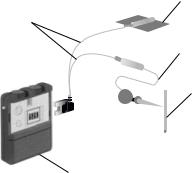
Testing Phase (See Fig. 1). The testing hardware consists of a needle, test lead, test stimulator, interconnect cabling and a ground pad (Fig. 1).
Needle (see Figs. 2 and 3).
A 20-gauge foramen needle with a bevelled tip is used to gain access to the sacral nerve for placing the test stimulation lead. The stainless steel needle is depth-marked along its length and electrically insulated along its center length. The portion near the hub is exposed to allow connection to
Ground pad
Interconnect cables
Test lead
Needle
Test stimulator
Figure 1. Test stimulation system.
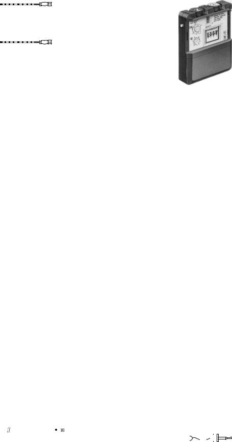
Figure 2. Model 041828 (20 gauge) 3.5 in. (88.9 mm) foramen needles.
Figure 3. Model 041829 (20 gauge) 5 in. (127 mm) foramen needles.
the test stimulator. By stimulating through the uninsulated tip of the needle, the physician can determine the correct SNS site for the test stimulation lead.
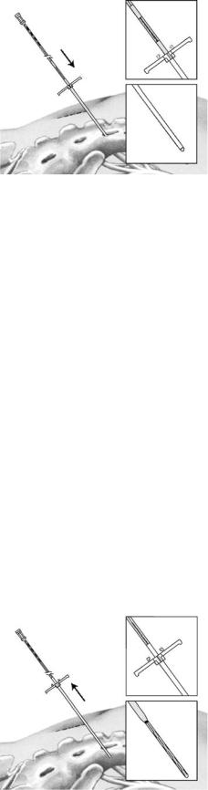
Test lead (see Fig. 4).
The initial test lead is a peripheral nerve evaluation (PNE) test lead with a coiled, seven-stranded stainless steel wire coated with fluoropolymer. Its electrode is extended to 10 mm (0.4 in.) to increase the length of coverage and reduce the effects of minor migration. Depth indicators help to align the lead electrode with the needle tip. The lead contains its own stylet, which is removed once the correct position has been found, leaving the lead flexible and stretchable, to mitigate migration.
Test stimulator (see Fig. 5).
The most current version of test stimulators is the model 3625. The model 3625 test stimulator can be used both for patient screening, where the patient is sent home with the device, and for intraoperative usage in determining lead placement thresholds. It provides output characteristics that are similar to those of the implantable neurostimulator and can be operated in either monopolar or bipolar modes. It is battery operated by a regular, 9 V battery. The physician sets the maximum and minimum amplitude settings, allowing the patient to control the amplitude (within those maximum and minimum settings) to whatever level is comfortable.
The safety features of the stimulator include; an automatic output shut-off occurs when the amplitude is turned up too rapidly (as when the control is inadvertently bumped), a loose device battery will cause output shutoff also to prevent intermittent stimulation and shock to the patient, and sensors, which detect when electrocautery is being used, shut the output off. Turning the test stimulator off for a minimum of 3 s can reset the protection circuitry.
Interconnect cables (see Fig. 6).
Single-use electrical cables are used to hook the test stimulation lead to the model 3625 test stimulator during the test stimulation procedure in the physician’s office
BLADDER DYSFUNCTION, NEUROSTIMULATION OF |
433 |
Figure 5. Model 3625 sacral nerve test stimulator.
and when the patient goes home for the evaluation period.
The patient cable is used to deliver acute stimulation during the test procedure. The insulated tin-plated copper cable has a 2 mm socket at one end and a spring-activated minihook at the other end. The minihook makes a sterile connection to the foramen needle, test stimulation lead, or implant lead. The socket end is connected to the test stimulator by a long screener cable, the latter being a two-wire cable with a single connector to the model 3625 test stimulator at one end; one of the wires is connected to the patient cable and the other to the ground pad. After the test stimulation, the patient cable is removed and a short screener cable is substituted for at-home use. This cable is connected to the ground pad and directly to the test lead. It is designed to withstand the rigours of home use and can be disconnected, to facilitate changing clothes (13).
Ground pad.
The ground pad provides the positive polarity in the electrical circuit during the test stimulation and the at-home trial. It is made of silicone rubber and is adhered to the patient’s skin. As described above, for the at-home trial a short screener cable is substituted for the long screener cable and connected directly to the lead.
Surgical Technique Used for Acute Testing Phase:. The aims of percutaneous neurostimulation testing (PNE) are to check the neural and functional integrity of the sacral nerves, to determine whether neurostimulation is beneficial for each particular patient, and to clarify which sacral spinal nerves must be stimulated to achieve the optimum therapeutic effect in each individual case.
Local anesthetic is injected into the subcutaneous fatty tissue and the muscles, but not into the sacral foramen itself. The S3 foramen is localized on one side with a 20gauge foramen needle. By stimulating through the uninsulated tip of the needle, the physician can find the correct sacral nerve stimulation site for placement of the test stimulation lead. Once the location of the S3 foramen is established, tracing of the other foramina is done. The
|
|
|
|
|
|
|
|
|
|
|
|
|
|
|
|
|
|
|
|
|
|
|
|
|
|
|
|
|
|
|
|
|
|
|
|
|
|
|
|
|
|
|
|
|
|
|
|
|
|
Figure 4. Model 3057 test stimulation lead. |
|
|
|
|
|
|
|
|
|
|
|
|
||||||||||||
Figure 6. Model 041831 patient cable. |
||||||||||||||||||||||||
434 BLADDER DYSFUNCTION, NEUROSTIMULATION OF
portion near the hub is exposed to allow connection to the test stimulator.
Keeping the needle at a 608 angle to the skin surface with a rostrocaudal and slightly lateral pointing tip of the needle will ensure that the needle is inserted into the targeted foramen. The puncture should progress parallel to the course of the sacral nerve, which normally enters at the upper medial margin of the foramen. This method achieves optimal positioning of the needle for stimulation and avoids injuring the spinal nerve. The insulated needle (cathode) is then connected to an external, portable pulse generator (Medtronic model 3625 test stimulator) via a connection cable. The pulse generator itself is connected to a neutral electrode (anode) attached to the shoulder.
Because patient sensitivity varies, the voltage used is between 1–6 V, which starts at 1 and is increased in 20 Hz increments. Stimulation of the S3 evokes the ‘‘bellows’’ effect (contraction of the levator ani and the sphincter urethrea). Also, there is plantar flexion of the foot on the ipsilateral side. If plantar flexion of the entire foot is observed, the gastrocnemius muscle should be palpated, because a strong contraction usually indicates stimulation of S2 fibers and should be avoided.
Stimulation of S3 generally produces the most beneficial effect. Furthermore, most patients will not tolerate the permanent external rotation of the leg caused by stimulation of S2. Occasionally, stimulating S4 also causes clinical improvement. Stimulation of S4 provokes a strong contraction of the levator ani muscle, accompanied by a dragging sensation in the rectal region. If stimulating one side produces an inadequate response, the contralateral side should be tested; the aim is to obtain a typical painless stimulatory response.
Once the optimal stimulation site has been identified, the obturator is removed from the foramen needle, and a temporary wire test lead (Medtronic model 3057 test lead) is inserted through the lumen of the needle. Once the test lead has been inserted into the needle, the latter must not be advanced any further in order to avoid severing the lead. The needle is then carefully removed from the sacral foramen, leaving the test lead in place. The stimulation is then repeated to check the correct position of the test electrode. To mitigate migration the lead contains its own stylet, which is removed once the correct position has been found, leaving the lead flexible and stretchable.
A repetition of the test stimulation, confirming the correct position of the test lead, is therefore mandatory at this stage; otherwise the test lead cannot be reinserted.
After correct positioning, the test lead is coiled on the skin and fixed with adhesive transparent film. Finally, the correct position of the wire is radiologically confirmed and the portable external impulse generator is connected.
Percutaneous Extension Hardware (see Fig. 7). If acute testing is inconclusive, or when there is a need for positive fixation of the test lead, percutaneous extension hardware is the best method used. Also called the staged implant, it is an alternative method for patient screening.
The chronic lead is implanted in the normal manner and is connected to a percutaneous extension (model 3550-05). The extension is designed to provide a connection between
Stimulator cable
Percutaneous extension
Connector
Test stimulator
Connector
|
|
|
|
|
|
|
|
|
|
|
|
|
|
Lead electrodes |
Anchor sleeve |
Lead |
|||||||||||
Figure 7. Percutaneous extension system.
the chronic lead and the external test stimulator. Positive contact is made using four set screws; the connection is sealed with a silicone boot that covers the set screws. The percutaneous extension, which is intended for temporary use, features four insulated wires, wound together and sized for a small incision, so that they can be brought through the skin. The percutaneous extension is then connected to the screener cable, as described above (13).
Chronic System. The chronic system consists of an implantable neurostimulator, a lead, an extension, a physician programmer and a patient programmer.
Neurostimulator (see Fig. 8).
The implantable neurostimulator (Medtronic model 3023) weighs 42 g and has a volume of 22 cm3. It comprises70% battery and 30% electronics. The physician has unlimited access to programmable parameters such as amplitude, frequency, and pulse width. Each parameter can be changed by means of an external, physician programmer that establishes a rf link with the implanted device. A patient programmer provides limited access to allow the patient to turn the neurostimulator on and off, or to change amplitude within a range established by the physician (via the physician programmer) (13).
The external titanium container of the neurostimulator may be used in either a monopolar configuration (lead negative, can positive) or a bipolar configuration, which will result in marginally better longevity. The life of the neurostimulators is usually 7–10 years. Factors that affect this are the mode, programming of the amplitude, pulse width and frequency, and the use of more than one active electrode.
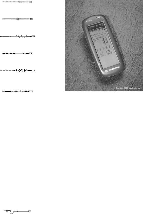
Implantable lead system (see Fig. 9–14).
Figure 8. Model 3023 implantable neurostimulator.
BLADDER DYSFUNCTION, NEUROSTIMULATION OF |
435 |
Figure 9. Model 3080 lead.
Figure 10. Model 3092 lead.
Figure 11. Model 3093 lead.
Figure 12. Model 3886 lead.
Figure 13. Model 3889 lead.
Figure 14. Model 3966 lead.
The lead is a quadripolar design, with four separate electrodes that can be individually programmed to plus, minus, or off. This allows the physician to optimize the electrode configuration for each patient and to change programming, without additional surgery, at a later date, to adapt to minor lead migration or changing disease states. The electrode sizes, spacing, and configurations have been designed specifically for SNS.
The lead is supplied with multiple stylets and anchors, to accommodate physician preferences. A stylet (straight or bent) is inserted into the lumen of the lead to provide extra stiffness during implant. Two different degrees of stiffness provide the physician with options to tailor the handling and steering properties of the lead, as preferred. The stylet must be removed before connection with the mating component.
The physician also has a choice of anchors, which allow fixation of the lead to stable tissue to prevent dislodging of the lead after implantation. Three anchor configurations are available: a silicone rubber anchor fixed in place on the lead has wings, holes and grooves to facilitate suturing; a second type, also made of silicone, slides into place anywhere along the lead body, and must be sutured to the lead to hold it in place; a new plastic anchor is also available, which can be locked in place anywhere along the lead body without a suture to the lead.
Quadripolar extension (see Fig. 15).
Figure 15. Series 3095 extension.
Figure 16. Physician programmer.
The quadripolar extension, which is available in varying lengths to facilitate flexibility in IPG placement, is designed to provide a sealed connection to the lead. This extension provides the interface with the neurostimulator. Positive contact is made with four set screws, and the connection is sealed with a silicone boot covering the screws.
Physician programmer (Fig. 16).
The console programmer (Medtronic model 8840 N’Vision) is a microprocessor-based system that the physician uses to program the implanted neurostimulator noninvasively. The programmer uses an application-spe- cific memory module, installed by means of a plug-in software module.
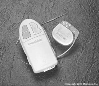
Patient programmer (Fig. 17).
The patient programmer also communicates with the implanted neurostimulator by an rf link. The patient can adjust stimulation parameters within the range set by the physician. This range is intended to allow the patient to turn the device on or off, and to change amplitude for comfort (as during postural changes), without returning to the physician’s office.
Surgical Technique Used for Chronic Implantable System. The sacral foramen electrode and impulse generator are implanted under general anesthesia. Long-acting muscle relaxants must not be used, as these would impair the intraoperative electrostimulation.
The patient is placed in the prone position with a 458 flexion of the hip and knee joints. An 8 cm long midline
436 BLADDER DYSFUNCTION, NEUROSTIMULATION OF
Figure 17. Patient programmer.
incision is made above the sacrum, reaching one-third caudal and two-thirds cranial from the S3 foramen. After transection of the subcutaneous fat, the muscle fascia (thoracolumbar fascia) is incised approximately 1 cm lateral of the midline in a longitudinal direction.
Usually, the Gluteus maximus has to be incised over a length of 1–2 cm for good exposure of the S3 foramen and a little further caudal if implantation of the S4 foramen is intended. The paraspinal muscles are then divided longitudinally and the dorsal aspect of the sacrum is exposed.
Intraoperative test stimulation, using the same equipment as for the acute testing phase, will confirm the precise location of the foramen selected. The foramen needle is left in place to avoid relocalisation of the foramen while preparing the permanent electrode for implantation. Proximal to the four contact points of the permanent electrode, a silicon rubber cuff is glued to the electrode body. The cuff is fitted with three eyelets to accommodate nonabsorbable atraumatic needle-armed sutures.
After removal of the foramen needle, the permanent electrode (Medtronic quadripolar lead, model 3080) is gently inserted into the foramen. Renewed test stimulation will determine the most effective contact point between the electrode and spinal nerve; the most distal contact point is termed ‘‘0’’, with the subsequent three being numbered 1–3 sequentially. An identical motor response at all four contact points is ideal. If only one contact gives a satisfactory response, the electrode should be repositioned at a different angle to the foramen and the test stimulation repeated. The preattached sutures are then used to secure the electrode to the ligaments overlying the periosteum of the sacral bone. Test stimulation should be repeated at this stage to confirm an appropriate position of the electrode after fixation.
A small skin incision is now made in the flank between the iliac crest and the 12th rib on the side where the electrode has been placed. A subcutaneous tunnel is formed between the two wounds, starting from the flank incision and running toward the sacral incision.
The obturator of the tunneling device is removed and the silicone sheath, which is open at both ends, left in place. The free end of the electrode is guided through the sheath to the flank incision, after the stylet has been removed from the electrode.
The silicone sheath is now removed from the flank incision, the proximal end of the electrode is marked with a suture, and the electrode is buried in a subcutaneous pocket that has been created at the site of the flank incision. The flank incision is temporarily closed, leaving the marking suture exposed between the skin sutures. The sacral incision is then closed in layers and covered with a sterile dressing.
The patient is now positioned on the contralateral flank. The flank and abdomen on the side chosen previously for placement of the Medtronic InterStim model 3023 implantable pulse generator are disinfected and the surgical field is draped with a sterile cover. The flank incision is now reopened, and a subcutaneous tunnel is again created between the flank incision and the subcutaneous pocket in the lower abdomen through which a connecting extension cable (Medtronic quadripolar extension, model 3095) between electrode and impulse generator is guided.
Once the electrode has been connected to the extension cable in the area of the flank incision, the contact point is sealed with a silicone cover, fixed with two sutures and placed subcutaneously. The flank incision is closed in layers and covered with a sterile dressing.
Finally, the other end of the connecting cable is attached to the impulse generator. The generator is attached to the rectus fascia using two nonabsorbable sutures. The abdominal incision is closed in two layers and covered with sterile dressings.
On the first postoperative day, anterior–posterior and lateral radiographs of the implant are obtained to verify that all components are correctly positioned and will act as a control for comparison in case of subsequent problems.
Modifications of the surgical procedure include placement of the pulse generator in the gluteal area thus avoiding repositioning of the patient during the procedure and implantation of bilateral electrodes, which should be powered by a two-channel pulse generator (Medtronic Synergy, model 7427) for adequate synchronous independent stimulation of each side. The implant remains deactivated at least until the day following surgery and will be activated by a telemetric programming unit (Medtronic Console Programmer, model 7432) allowing programming of all features of the implant by the physician during the initial activation and follow-up stages.
NEW MEDTRONIC TINED LEAD PERCUTANEOUS IMPLANT (SEE FIGS. 18 AND 19)
Tined leads offer sacral nerve stimulation through a minimally invasive implant procedure. The use of local anesthesia allows for patient sensory response during the implant procedure. This response helps ensure optimal lead placement and may result in better patient outcomes. With previous lead designs, many physicians used general anesthesia, which did not allow for patient sensory response.
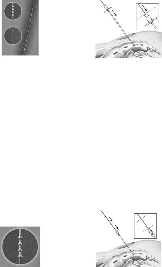
Figure 18. Tined lead percutaneous implant.
Among the advantages of the minimally invasive implant procedure are the radiopaque markers to identify where tines are deployed, helping physicians in identifying the exact lead location relative to the sacrum and nerves. Tactile markers indicate lead deployment, and a white marker bands on the lead and tactile markers aid in proper lead placement and to notify the physician when the tines are ready to be deployed.
Percutaneous lead placement allows use of local anesthesia. This reduces the risks of general anesthesia and surgical incision and may facilitate faster patient recovery time as a result of less muscle trauma and a minimized surgical incision. Also, it may reduce surgical time as a result of a sutureless anchoring procedure and reduced number of surgical steps.
To date, a positive response to the PNE test has been the only predictive factor for the long-term efficacy of sacral nerve stimulation therapy. Current studies show that up to 40% of patients who experience improvement in symptoms during PNE test stimulation with a temporary lead do not have this improvement carried through after neurostimulator implantation (36). A study by Spinelli et al. looked at patients who underwent tined lead implant without PNE testing, and reported a positive outcome of 80% during the screening phase, which was maintained at an average follow up of 11 months, resulting in a higher success rate than that currently reported in the literature (37).
The development of the new tined lead allows fully percutaneous implantation of the permanent lead and offers the possibility of a longer and more reliable screening period than that possible with the PNE test. The advantage for patient screening are that the permanent tined lead is less prone to migration, hence if the results of screening are
BLADDER DYSFUNCTION, NEUROSTIMULATION OF |
437 |
Figure 20. The foramen needle stylet and directional guide.
positive, the lead is already in the precise place where positive results were obtained, and there is a decrease in false-positive and false-negative results after screening (37). However, use (or lack thereof) of PNE testing in conjunction with the tined lead differs from center to center, depending on fiscal and/or other reasons.
The tined lead models 3093 and 3889 are designed to work with the current lead introducer model 355018 or 042294.
Surgical Technique for Tined Lead Implant. The foramen needle is inserted and tested for nerve response. The foramen needle stylet is then removed and replaced with the directional guide (see Fig. 20). The foramen needle itself is then removed.
A small incision is made on either side of the directional guide, which is followed by fitting the dilator and the introducer sheath over the directional guide and advanced into the foramen (see Fig. 21). The guide and the dilator are then removed, leaving the introducer sheath in place.
The lead is then inserted into the introducer sheath and advanced until visual marker band C on the lead lines up with the top of the introducer sheath handle. Using fluoroscopy, electrode 0 of the lead is confirmed to be proximal to the radiopaque marker band at the distal tip of the sheath (see Fig. 22).
While holding the lead in place, the introducer sheath is retracted until visual marker band D on the lead lines up with the introducer sheath handle. Using fluoroscopy, radiopaque marker band at the tip of the sheath is
Figure 19. Tined lead percutaneous implant. |
Figure 21. Fitting the dilator and introducer sheath. |
438 BLADDER DYSFUNCTION, NEUROSTIMULATION OF
Figure 22. Confirming lead proximal to radiopaque marker band.
confirmed to be proximal to electrode 3 and adjacent to radiopaque marker band A on the lead (see Fig. 23).
Test stimulation of the various electrodes (0, 1, 2, 3) is done and the responses are observed. If necessary, the lead is repositioned within the foramen. When the lead is in the proper position, the lead is held in place and the introducer sheath and lead stylet are carefully withdrawn, thereby deploying the tines and anchoring the lead.
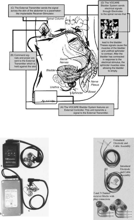
FINETECH–BRINDLEY (VOCARE) BLADDER SYSTEM
Introduction (see Fig. 24)
Indications for use: The VOCARE bladder system is indicated for the treatment of patients who have clinically complete spinal cord lesions with intact parasympathetic innervation of the bladder and are skeletally mature and neurologically stable. However, patients with other neurological disorders, including multiple scleroses, spinal cord tumours, transverse myelitis, cerebral palsy and meningomyelocele, have also benefited from the implant(38). A secondary use of the device is to aid in bowel evacuation and promote penile erection.
The sacral anterior root stimulation (SARS) system was developed by Brindley with the support of the Medical Research Council (Welwyn Garden City, Herts, UK), is manufactured by Finetech Medical Ltd. in England, and is
Figure 23. Confirming marker band proximal to electrode 3.
marketed as the Vocare system by NeuroControl Corporation (Cleveland, OH) (1).
Beginning in 1969, Brindley developed a new device to stimulate sacral roots at the level of the cauda equina. This technique, first tested in baboons, led to the development of a stimulator that was first successfully implanted in a patient in 1978 (39).
Hardware
The Finetech–Brindley bladder controller is composed of external and internal equipment.
1. External (see Fig. 25):
One analog and three digital versions of the external controller are available in different countries (1). This device has no batteries but is powered and controlled by rf transmission from a portable external controller operated by the user and programmed by the clinician. It consists of a transmitter block connected to the control box via a transmitter lead. The patient holds the transmitter over the implanted receiver to apply stimulation. A new, smaller control box that is more powerful will be available in the coming months (39).
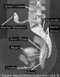
2. Internal (see Fig. 26):
The internal equipment consists of three main parts:
(1) the electrodes, (2) the cables, (3) and the receiver block.
Two types of electrodes are used, depending on the approach (intraor extradural).
For intradural implantation the electrode mounts in which the anterior sacral roots are trapped are called ‘‘books’’ because of their shape.
The two-channel implant has an upper book with only 1 slot. Trapping of S3 and S4 roots is often sufficient to obtain bladder contractions. In males, S2 roots were trapped in the upper book and S3 and S4 roots, in the lower book.
The three-channel implant is composed of two electrode books. The upper book contains three parallel slots for S3 and S2 roots and the lower contains one slot for S4 roots. There are three electrodes in each slot (one cathode in the center and two anodes at the two ends) to avoid stimulation of unwanted structures.
The four-channel implant has two books like those of the threechannel implant, and the four slots allow independent stimulation of four sets of nerve fibers. It is used in patients who retained sacral-segment pain sensitivity.
The special eight-channel implant allowed the stimulation of four anterior roots and the destruction of any of the four posterior roots, if necessary, after implantation. It is no longer used.
For extradural implantation the cables end with three helical electrodes (a cathode between two anodes) and are attached to the roots with a strip of Dacron-reinforced silicone rubber. The cables used
BLADDER DYSFUNCTION, NEUROSTIMULATION OF |
439 |
Figure 24. VOCARE bladder system.
Figure 25. External equipment. (a) New control box. (b) Original |
|
control box. (c) Transmitter lead. (d) Transmitter block. |
Figure 26. Internal equipment. |
440 BLADDER DYSFUNCTION, NEUROSTIMULATION OF
Figure 27. Finetech–Brindley system.
are encapsulated in silicone rubber, and the wires are made of 90% platinum and 10% iridium and connect the electrodes to the radio receiver block. The radio receiver block, which contains two, three, or four radioreceivers imbedded in silicone rubber, is activated by pulse-modulated rf waves (39).
Surgical Technique for Finetech–Brindley System (see Fig. 27):. The surgical technique for intrathecal implantation developed by Brindley et al. (40) involves laminectomy of the fourth and fifth lumbar vertebrae and the first two pieces of the sacrum, exposing 10–12 cm of dura. The dura and arachnoid are opened at the midline to expose the roots. The roots are identified by their size and situation and by perioperative stimulation during the recording of bladder pressure and observation of skeletal muscle responses with the naked eye.
The S2 anterior roots contract the triceps surae, the glutei, and the biceps femoris. The S3 anterior roots innervate the pelvic floor and the toe flexors. The S4 anterior roots innervate the pelvic floor. The sphincters (anorectal and urethral) are innervated predominantly by S4 and also by S3 and S2. The detrusor response is always obtainable by stimulation of S3 and S4 and sometimes achievable by stimulation of S2.
The roots are split into the anterior and posterior components. The identity of the posterior root is confirmed by electrical stimulation and then a segment measuring 20– 40 mm in length is removed. When the S5 root has been identified, it is resected if no bladder response is obtained (39).
If a posterior rhizotomy is performed, stimulation can be applied to mixed sacral nerves in the sacral spinal canal extradurally, since the action potentials generated on the afferent axons do not reach the spinal cord. This has the advantage that the electrodes can be placed extradurally, reducing the risk of leakage of cerebrospinal fluid along the cables, and reducing the risk of breakage of the cables where they cross the dura. In addition, the extradural
nerves are more robust than the intradural roots, being covered with epineurium derived from the dura, and require less dissection than the intradural roots; therefore, there is less risk of neuropraxia of the axons, which could otherwise lead to a delay in usage of the stimulator but not usually in permanent loss of function (1,41).
The benefits of a posterior rhizotomy include abolition of the neurogenic detrusor over activity, resulting in increased bladder capacity and compliance, reduced incontinence, and protection of the kidneys from ureteric reflux and hydronephrosis. The rhizotomy also reduces detrusorsphincter dyssynergia, which improves urine flow, and prevents autonomic dysreflexia arising from distension or contraction of the bladder or bowel. In addition, a posterior rhizotomy improves implant-driven micturition. However, there are also drawbacks with a rhizotomy. They include abolition of reflex erection, reflex ejaculation, reflex defecation and sacral sensation, if present. Still, in many subjects with spinal lesions, these reflexes are not adequately functional, and function can be restored by other techniques (42).
The surgical technique for extradural implantation involves laminectomy of the first three pieces of the sacrum. It may also involve laminectomy of the L5 vertebra, depending on whether it is decided to implant electrodes on S2 roots (39). Extradural electrodes are used for patients in whom arachnoiditis makes separation of the sacral roots impossible. In some centers, however, extradural electrodes are used for all or nearly all patients.
After electrode implantation, the operation proceeded with closure of the dura, tunneling of the leads to a subcutaneous pocket in the flank, and closure of the skin. The patient is turned over and the leads are prepared for connection to the implantable stimulator.
At this time the leads are connected via an aseptic cable to an experimental stimulator. Prior to stimulation the bladder is filled with 200 mL saline using a transurethral filling catheter. The experimental stimulator consisted of two synchronized current sources with a common cathode. Pressure responses are elicited using pulse trains of 3–5 s duration; containing identical monophasic rectangular pulses delivered at a rate of 25 pulses s 1. Stimulation is usually limited to the S3 and S4 ventral roots since they contain most of the motoneurons innervating the lower urinary tract.
After 15–20 min of experimental stimulation the leads are disconnected from the stimulator and the normal procedure is resumed with implantation stimulator.
A two-channel transurethral pressure catheter is used to measure intravesical and intraurethral pressure. The urethral pressure sensor is positioned at the level of the external sphincter such that in response to suprathreshold stimulation a maximal pressure response is measured. Pressures are sampled at 8 Hz, displayed on a monitor, and stored in a portable data logger (43).
All patients are followed up according to a fixed protocol. Urodynamic measurements are taken at 2 days, 15 days, 4 months, and 1 year after surgery and every 2–3 years thereafter. Renal ultrasound examination is performed every year. Stimulation is performed for the first time
BLADDER DYSFUNCTION, NEUROSTIMULATION OF |
441 |
Figure 28. BION microstimulator.
between days 8 and 14, depending on the level of the spinal cord lesion (33).
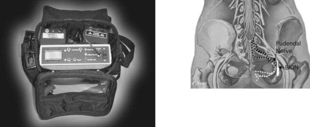
PUDENDAL NERVE STIMULATION FOR THE TREATMENT OF THE OVERACTIVE BLADDER (rf BION) (SEE FIGS. 28 AND 29)
Indications for use: The rf Bion system is still relatively new, and though no clear, established indications have been set so far, its activity on the pudendal nerve and inhibition of the detruser muscle makes it ideal for overactive bladder disorders.
Electrical stimulation of the pudendal nerve has been demonstrated to inhibit detrusor activity and chronic electrical stimulation may provide effective treatment for overactive bladder disorders (44). The hurdle to date has been the technical challenge of placing and maintaining an electrode near the pudendal nerve in humans; however, recent development of the BION has made chronic implantation feasible.
The BION is a small, self-contained microstimulator that can be injected directly adjacent to the pudendal nerve (see Fig. 28). The ischial spine is an excellent marker for the pudendal nerve as it re-enters the pelvis through Alcock’s canal. This is a very consistent anatomical landmark in both men and women. Also, the implanted electrode is protected in this area by both the sacral tuberous and sacrospinous ligaments. Stimulation in this area activates afferent innervation over up to three sacral segments. Efferent stimulation also provides direct activation of the external urethral sphincter, the external anal sphincter, and the levator ani muscles, which may be of some benefit in bladder control. The external components of this neural prosthesis include a coil that is worn around the subject’s hips and a controller that is worn around the shoulder or waist.
The technique chosen to implant the device is that of the transperineal pudendal block. This approach is minimally invasive and is well established. A special implant tool was
Figure 29. Placement of BION system near pudendal nerve.
devised to facilitate placement. The BION implantation technique was developed in cadavers. The optimum insertion location is 1.5 cm medial to the ischeal tuberosity using a vaginal finger to guide the implant toward the ischial spine where electrical stimulation of the pudendal nerve may be confirmed (see Fig. 29).
A percutaneous stimulation test (PST) was developed and proved to be a very effective way to assess acute changes in bladder volumes while stimulating the pudendal nerve. A baseline cystometrogram (CMG) was obtained followed by percutaneous pudendal nerve stimulation for 10 min with a repeat CMG.
The first implant was done on August 29, 2000. The BION was implanted under local anesthesia with intravenous sedation. Proper placement was verified by palpation and EMG activity. An intermittent stimulation mode of 5 s on 5 s off was used. Subjects returned 5–7 days later for activation, to distinguish between postoperative pain and potential stimulation pain. Subjects were followed up at 15, 30, and 45 days after activation. At each follow-up visit they underwent another cystometrogram and brought in a 72 h voiding diary. The results indicated a favorable response to maximum cystometric capacity throughout the study period. Diary entries verified improvement— incontinent episodes decreased by 65%, and both daytime and nighttime voids were decreased, as was pad use per day.
FUTURE DIRECTION OF THE THERAPY HARDWARE
The ongoing development of tools and hardware is driven by the desire to reduce the invasiveness of the implant and the likelihood of adverse events. Development efforts are concentrated on system components and tools that will allow implantation of the lead system through small incisions or percutaneous approaches. It is inevitable that the size of the neurostimulator will be reduced as future generations of the device are developed; more efficient power batteries and packaging will drive this aspect of development.
A rechargeable power battery may allow a smaller device. Although a smaller device would be welcomed, attaining this goal with a rechargeable battery is not seen as the best approach. A rechargeable neurostimulator would
442 BLADDER DYSFUNCTION, NEUROSTIMULATION OF
require the patient frequently to recharge the unit; this would inconvenience the patient and could reduce patient compliance. Additionally, a rechargeable battery would be more expensive than a nonrechargeable one owing to the technology required and the additional equipment necessary for recharging. Furthermore, this would not eliminate the need for periodic replacement of the neurostimulator every 5–10 years. System components will be optimized for the therapy, to reduce the time needed for management of both implant and patient. The incorporation of microprocessors and implementation of features such as a battery gauge will provide additional operational information while decreasing the time needed to manage the patient.
Physicians will be able to analyze system use, lead status, and other parameters. The addition of sensing technology may provide an opportunity to create a closed-loop system that captures data to optimize both diagnosis and functioning.
Bilateral stimulation may provide more efficacious therapy. There is considerable interest in this approach, and it seems to be a probable avenue of research in the near future. However, any use of bilateral stimulation would have to justify the larger neurostimulator, the extra lead system, and the additional costs associated with this approach; at present, there is no scientific experience to support this approach.
Apart from a reduction in the size of the implanted device, enhanced physician control is the most likely development to occur in the foreseeable future. Graphics-based programming and control will simplify device programming; it will allow more complex features to be incorporated in the neurostimulator without adding undue complexity to the physician programmer. Management of patient data files will become easier as additional data-management features are added to the programmer; the physician will be able to obtain a patient-programming history and other patient-management data. It is conceivable that, in the not-so-distant future, the physician may be able to access patient-device data over the Internet, thus making unnecessary some clinic visits and allowing for remote follow-up of patients who are on holiday or have moved house.
Future devices may allow software loading in a noninvasive manner, to upgrade the device long after implantation. Such capability could be used to provide new therapy algorithms as well as new therapy waveforms.
The future will also bring enhanced test stimulation devices, which will provide improved fixation during the test stimulation period. The development of new leads is one such focus with the aim of allowing a longer test stimulation period without lead migration.
The future application of SNS is dependent on new clinical research. Pelvic disorders, such as pelvic pain and sexual dysfunction, appear likely to be the First areas of investigation; sacral anterior root stimulation for spinal cord injury may also provide a worthwhile avenue of enquiry. The development of these applications—or of any other, for that matter—will potentially require new waveforms and the development of new therapy algorithms. The future is as open as the availability of resources and the application of science allow (45).
BIBLIOGRAPHY
Cited References
1.Jezernik S, Craggs M, Grill WM, et al.Electrical stimulation for the treatment of bladder dysfunction: current status and future possibilities. Neurol Res 2002;24(5):413–430.
2.Galvani L. De virfbus electricitatis in motu musculari, commentaffus. De Bononiensi Scientarium et Artium Instituto Atque Academia. 1791;7:363–418.
3.Volta A. Letter to Sir Joseph Banks, March 20, 1800. On electricity excited by the mere contact of conducting substances of different kinds. Philos Trans R Soc London (Biol) 1800;90:403–431.
4.Duchenne GBA. De I’dlectrisation localisde et de son application & la physiologie, & la pathologie et b la therapeutique. Paris; 1855.
5.Duchenne GBA. Physiologie des moumments demonstrde b I’aide de I’experimentation electrique et de l’observation clinique, et applicable b I’6tude des paralysies et des deformations. Paris; 1867.
6.Chaffee EL, Light RE. A method for remote control of electrical stimulation of the nervous system. Yale J Biol Med 1934;7:83.
7.Glenn WWL, Phelps ML. Diaphragm pacing by electrical stimulation of the phrenic nerve. Neutosurgery 1985; 17:974–1044.
8.Glenn WWL, Mauro A, Longo E, et al.Remote stimulation of the heart by radiofrequency transmission. N Engl J Med 1959;261:948.
9.House WF. Cochlear implants. Ann Otol Rhinol Laryngol 1976;85(27):1–93.
10.Saxtorph MH. Strictura urethrae—Fistula petinei—Retentio urinae. Clinisk Chirurgi. Copenhagen: Gyldendalske Fodag; 1878.
11.Katona F, Benyo L, Lang J. Uber intraluminare elektrotherapie vor verschiedenen paralytischen zustlinden des gastrointestinalen tractes mit quadrangularstrom. Zentralbl Chir 1959;84:929.
12.Matona F. Stages otvegetative afferentation in reorganization of bladder control during electrotherapy. Urol Int 1975;30:192–203.
13.Schlote N, Tanagho EA. Electrical Stimulation of the lower urinary tract: historical overview. In: Jonas U, Grunewald V, editors. New Perspectives in sacral nerve stimulation. Dunitz; 2002. p 1–8.
14.McGuire WE. Response of the neurogenic bladder to vadous electrical stimuli [dissertation]. Department of Surgery, Bowman Gray School of Medicine; 1955.
15.Boyce WH, Lathem JE, Hunt LD. Research related to the development ofan artificial electrical stimulator for the paralyzed human bladder: a review. J Urology 1964;91:41–51.
16.Bradley WE, Chou SN, French LA. Further experience with the radio transmitter receiver unit for the neurogenic bladder. J. Neurosurg 1963;20:953–960.
17.Caldwell KPS. The electrical control of sphincter incompetence. Lancet 1963;2:174.
18.Fall M, Erlandson BE, Carlsson CA, Lindstr6m S. The effect of intravagnal electrical stimulation on the feline urethra and urinary bladder. Scand) Urol Nephrol (Supp) 1977;44: 19–30.
19.Lindstrim S, Fall M, Carlsson CA, Edandson BE. The neurophysiologcal basisaf bladder inhlbition in response to intravaginal electrical stimulation. Urology 1983;129:405–410.
20.McGuire EL, ZIang SC, Horwinski ER, Lytton B. Treatment of motor and sensory detrusor instability by electical stimulation. J Urol 1983;129:78–79.
21.Govier FE, Litwiller S, Nitti V, Kreder KJ, Jr., Rosenblatt P. Percutaneous afferent neuromodulation for the refractory