


A
ABLATION. See TISSUE ABLATION.
ABSORBABLE BIOMATERIALS. See BIOMATERIALS,
ABSORBABLE.
ACRYLIC BONE CEMENT. See BONE CEMENT, ACRYLIC.
ACTINOTHERAPY. See ULTRAVIOLET RADIATION IN
MEDICINE.
ADOPTIVE IMMUNOTHERAPY. See IMMUNOTHERAPY.
AFFINITY CHROMATOGRAPHY. See
CHROMATOGRAPHY.
ALLOYS, SHAPE MEMORY
YOUNG KON KIM
Inje University
Kimhae City
Korea
INTRODUCTION
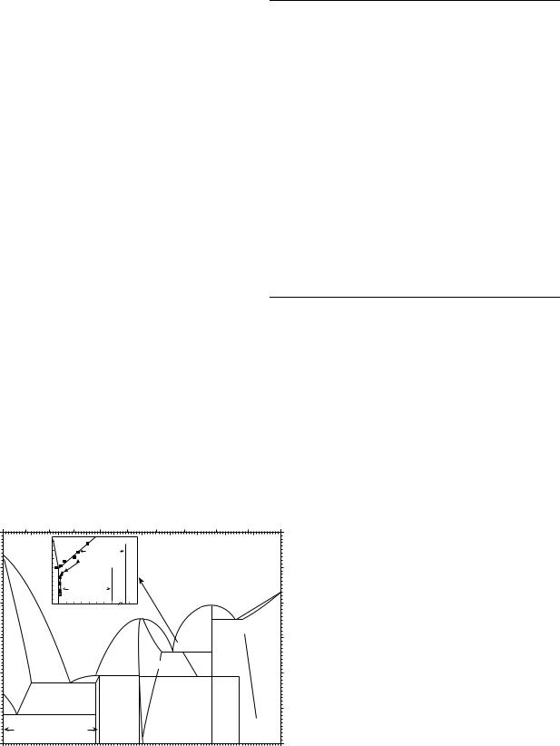
An alloy is defined as a substance with metallic properties that is composed of two or more chemical elements of which at least one is an elemental metal (1). The internal structure of most alloys starts to change only when it is no longer stable. When external influences, such as pressure and temperature, are varied, it will tend to transform spontaneously into a mixture of phases, the structures, compositions, and morphologies of which differ from the initial one. Such microstructural changes are known as phase transformation and may involve considerable atomic rearrangement and compositional change (2,3).
Shape memory alloys (SMAs) exhibit a unique mechanical ‘‘memory’’, or restoration force characteristic, when heated above a certain phase-transformation temperature range (TTR), after having been deformed below the TTR. This thermally activated shape recovering behavior is called the shape memory effect (SME) (3–5). This particular effect is closely related to a martensitic phase transformation accompanied by subatomic shear deformation resulting from the diffusionless, cooperative movement of atoms (6,7). The name martensite was originally used to describe the very fine, hard microstructure found in quenched steels (8). The meaning of this word has been extended gradually to describe the microstructure of nonferrous alloys that have similar characteristics.
SMAs have two stable phases: a high temperature stable phase, called the parent or austenite phase and a low temperature stable martensite phase. Martensite phases can be induced by cooling or stressing and are called thermally induced martensite (TIM) or stress induced martensite (SIM), respectively (8). The TIM forms and grows continuously as the temperature is lowered, and it shrinks and vanishes as the temperature is raised. The SIM is generated continuously with increasing applied stress on the alloy. On
removing the applied stress, SIM disappears gradually at a constant temperature. If the temperature is sufficiently low when stressing, however, the SIM cannot return to its initial structure when the stress is removed. When the temperature is increased above the TTR, the residual SIM restores the original structure, resulting in shape recovery (9). Surprisingly, this process can be reliably repeated millions of times, provided that the strain limits are not breached. If dislocations or slips intervene in this process, the shape memory becomes imperfect. When the applied stress on a SMA is too great, irreversible slip occurs, and the SMA cannot recover its original shape even after heating above TTR (10). However, it can remember this hot parent pattern. In the next cooling cycle, the SMA changes slightly and remembers the cool-martensite pattern. A SMA trained with this repeated cyclic treatment is called a two-way SMA (9). A schematic explanation of the SME related to the twodimensional (2D) crystal structure (11) is shown in Fig. 1. When a SMA is cooled below its TTR, the parent phase begins to form TIM without an external shape change. This TIM can be changed into SIM easily by mechanical deformation below the TTR. When the deformed SMA is heated above its TTR, however, it cannot hold the deformed shape anymore, and the SMA returns to its original shape, resulting in a reverse martensitic phase transformation.
A SMA also shows rubber-like behavior at temperatures above its TTR. When a SMA is deformed isothermally above its TTR, only SIM is produced, until plastic deformation occurs. Then, the SIM disappears immediately after removing the applied load, resulting in a much greater amount of recovering strain, in excess of the elastic limit, compared to the conventional elastic strain of a metal. This rubber-like behavior at a constant temperature above TTR is called superelasticity (12). A schematic explanation of superelasticity is shown in Fig. 2.
These contrasting behaviors of superelasticity and SME are a function of the testing temperature. If a SMA is tested below its TTR, it shows SME, while a SMA that is deformed above its TTR shows superelasticity.
It is convenient to subdivide the superelastic behavior into two categories, ‘‘superelasticity’’ and ‘‘rubber-like behavior’’, depending on the nature of the driving forces and mechanism involved. If it is triggered by SIM formation and subsequent reversion, the terminology superelasticity is used. By contrast, rubber-like behavior does not involve phase transformation, but involves deformation of the martensite itself. It is closely related to the reversible movement of deformed twin boundaries or martensite boundaries (10).
An example of SME in a shape-memory suture needle (13) is shown in Fig. 3. Figure 3a shows a curved needle with the shape preset by a heat-treatment process. When the shape-memory needle is cooled below its TTR, it is readily amenable to a change in shape with forceps (b). On heating it above TTR, thermal energy causes the needle to recover its original curved shape (c).
1

2 ALLOYS, SHAPE MEMORY
Parent phase
Cooling |
Heating |
TTR 
 TTR
TTR
Deformation |
Martensite phase |
Deformed martensite phase |
Figure 1. Schematic illustration of the shape memory effect. The parent phase is cooled below TTR to form a twinned (selfaccommodated) martensite without an external shape change. Deformed martensite is produced with twin boundary movement and a change of shape by deformation below the TTR. Heating above the TTR results in reverse transformation and leads to shape recovery.
|
|
|
|
|
|
|
|
|
|
|
|
|
|
|
|
|
|
|
|
|
|
|
|
|
|
|
|
|
|
|
|
|
|
|
|
|
|
|
|
|
|
|
|
|
|
|
|
|
|
|
|
|
|
|
|
|
|
|
|
|
|
|
|
|
|
|
|
|
|
|
|
|
|
|
|
|
|
|
|
|
|
|
|
|
|
|
|
|
|
|
|
|
|
|
|
|
|
|
|
Parent phase |
|
Stress induced martensite phase |
|||||||
Figure 2. Schematic illustration of the superelasticity of a SMA above TTR. During the loading process, the applied load changes the parent phase into stress-induced martensite, which disappears instantly on unloading.
(a)
Original shape |
|
Deformation |
Below TTR |
(b)
Deformed shape |
|
Heating |
Above TTR |
(c)
Recovered shape
Figure 3. Shape-memory effect in a SMA suture needle. (a) Cooling the SMA suture needle below its TTR, (b) straightening the SMA suture needle below its TTR, (c) recovering the original shape of the SMA suture needle above its TTR.
HISTORY OF SHAPE MEMORY ALLOYS
The first observed shape memory phenomenon was pseudoelasticity. In 1932, Oelander observed it in a Au–Cd alloy and called it ‘‘rubber-like’’ behavior (14). Owing to the great amount of reversible strain, this effect is also called ‘‘superelasticity’’. The SME was discovered in 1938 by Greninger and Mooradian (15), while observing the formation and disappearance of martensite with falling and rising temperature in a brass (Cu–Zn alloy) sample. The maximum amount of reversible strain was observed in a Cu–Al–Ni single crystal with a recoverable elastic strain of 24% (16). In 1949, Kurdjumov and Khandros (17), provided a theoretical explanation of the basic mechanism of SME, the thermoelastic behavior of the martensite phase in Au–Cd alloy. Numerous alloy systems have been found to exhibit shape memory behavior. However, the great breakthrough came in 1963, when Buehler et al. (4) at the U.S. Naval Ordnance Laboratory discovered the SME in an equiatomic alloy of Ni–Ti, since then popularized under the name nitinol (Nickel– Titanium Naval Ordnance Laboratory). Partial listings of SMAs include the alloy systems: Ag–Cd, Au–Cd, Au–Cu, Cu–Zn, Cu–Zn–X (X ¼ Si, Sn, Al, Ga),Cu–Al–Ni, Cu–Au–Zn, Cu–Sn, Ni–Al, Ni–Nb, Ni–Ti, Ni–Ti–Cu, Ti–Pd–Ni, In–Tl, In–Cd, Mn–Cd, Fe–Ni, Fe–Mn, Fe–Pt, Fe–Pd, and Fe–Ni–Co–Ti (9). It took several years to understand the microscopic, crystallographic, and thermodynamic properties of these extraordinary metals (18–20). The aeronautical, mechanical, electrical, biomedical, and biological engineering communities, as well as the health professions, are making use of shape memory alloys for a wide range of applications (9). Several commercial applications of Ni–Ti and Cu–Zn–Al SMAs have been developed, such as tubefitting systems, self-erectable structures, clamps, thermostatic devices, and biomedical applications (5,21–23).
Andreasen suggested the first clinical application of Ni–Ti SMA in 1971. He suggested that nitinol wire was useful for orthodontics by reason of its superelasticity and good corrosion resistance (24). Since then, Ni–Ti alloys have been used in a broad and continually expanding array of biomedical applications, including various prostheses and disposables used in vascular and orthopedic surgery. Medical interventions have themselves been driven toward minimally invasive procedures by the creation of new medical devices, such as guide wires, cardiovascular stents, filters, embolic coils, and endoscopic surgery devices. The Ni–Ti SMA stent was first introduced in 1983 when Dotter (25) and Cragg (26) simultaneously published the results of their experimental studies. However, their studies were unsuccessful because of the unstable introduction system and the intimal hyperplasia in the stent-implanted region (27). In 1990, Rauber et al. renewed the effort to use a Ni–Ti alloy as a stent, significantly reducing intimal hyperplasia by using a transcatheter insertion method (28). In 1992, Josef Rabkin reported successful results in the treatment of obstructions in vascular and nonvascular systems in 268 patients (29). In 1989, Kikuchi reported that a guidewire constructed from kink-resistant titanium– nickel alloy was helpful for angiography and interventional
procedures (30). Guidewires are used for needles, endoscopes, or catheters, to gain access to a desired location within the human body. In 1989, the U.S. Food and Drug Administration approved the use of a Mitek anchor constructed of nitinol for shoulder surgery (31). Since then, many devices and items have been developed with nickel–titanium SMAs.
NICKEL–TITANIUM SHAPE MEMORY ALLOY
Physical Properties
Some of the physical properties of 55-Nitinol are listed in Table 1 (32,33). Nitinol has good impact properties, low density, high fatigue strength, and a nonmagnetic nature. The excellent malleability and ductility of nitinol enable it to be manufactured in the form of wires, ribbons, tubes, sheets, or bars. It is particularly useful for very small devices.
Phase Diagram and Crystal Structures
A Ti–Ni equilibrium phase diagram (34) is very useful for understanding phase transformation and alloy design; a modified one is shown in Fig. 4 (35). There is a triangular region designated ‘‘TiNi’’ near the point of equiatomic composition. The left slope (solubility limit) is nearly vertical with temperature. This means that a precipitationhardening process cannot be used on the Ti-rich side in bulk alloys. By contrast, the right slope is less steep than the left. Therefore, the precipitation-controlling process can adjust transformation temperatures for practical application of SMAs on the Ni-rich side. The crystal structure of the upper part of this triangle, > 1090 8C, is body centered cubic (bcc). The lower part is a CsCl-type ordered structure (B2) from 1090 8C to room temperature. A schematic atomic configuration of the B2 structure is shown in Fig. 5 (36). In 1965, Wang determined the lattice constant
˚
of the B2 crystal as a0 ¼ 3.01 A (6). He proposed that the
|
|
|
ALLOYS, SHAPE MEMORY |
|
3 |
|
Table 1. Some of the Physical and Mechanical Properties |
||||||
of Nominal 55-Nitinola |
|
|
|
|||
Density |
|
|
|
6.45 g/cm3 |
|
|
Melting point |
1310 8C |
|
|
|||
Magnetic permeability coefficient |
< 1.002 |
|
|
|||
Electrical resistivity |
80 mV cm |
|
|
|||
20 8C |
|
|
|
|
|
|
900 8C |
|
|
132 mV cm |
|
|
|
Thermal expansion |
10.4 10 6/ 8C |
|
|
|||
Hardness, |
|
|
|
|
|
|
950 8C furnace cooled |
89 RB |
|
|
|||
950 8C quenched |
89 RB |
|
|
|||
Yield strength |
103–138 MPa (15–20 |
|||||
U.T.S. |
|
|
|
103 psi) |
3 |
psi) |
|
|
|
860 MPa (125 10 |
|
||
Elongation |
|
|
60% |
|
|
|
|
|
|
|
6 |
|
|
Young’s modulus |
70 GPa (10.2 10 6psi) |
|||||
Shear modulus |
24.8 GPa (3.6 10 |
|
psi) |
|||
Poisson’s ratio |
0.33 |
|
|
|||
Fatigue |
(Moore test) |
3 |
psi) |
|||
|
7 |
counts |
480 MPa (70 10 |
|
|
|
stress 10 |
|
|
|
|
||
Charpy impact |
|
|
|
|||
Unnotched (RT)b |
155 ftlb |
|
|
|||
Unnotched ( 80 8C) |
160 ftlb |
|
|
|||
Notched (RT) |
24 ftlb |
|
|
|||
Notched ( 80 8C) |
17 ftlb |
|
|
|||
aReproduced with permission from Biocompatibility of Clinical Implant Materials volume I, Ed. By D. F. Williams, 1981, Table 2 on page 136, Castleman L. S. and Motzkin S. M., copyright CRC press, Boca Raton Florida. See Refs. (32) and (33).
bRoom temperature ¼ RT.
Ni–Ti crystal structure is not a simple CsCl-type structure,
˚ ˚
but has a disordered 9 A superlattice and an ordered 3 A CsCl-type sublattice. As the temperature is lowered, the ordered CsCl structure is slightly tilted instantaneously and cooperatively into a close-packed structure, called martensite, with a 2D dimensional close-packed plane (basal plane) (6,37). The martensite unit cell is described as a monoclinic (B190) configuration, as shown in Fig. 6.
|
|
|
|
|
|
|
Nickel content (wt%) |
|
|
|
|
|
|||
|
1800 |
0 |
10 |
20 |
|
30 |
40 |
50 |
60 |
70 |
80 |
90 |
100 |
|
|
|
|
(°C) |
|
|
|
TiNi3 |
|
|
|
|
|
|
|
||
|
|
|
927 |
TiNi |
|
|
|
|
|
|
|
||||
|
1670°C |
|
Temperature |
727 |
|
TiNi + TiNi3 |
|
|
|
|
|
|
|
|
|
|
|
|
|
Ti3Ni4 |
|
|
|
|
|
|
|
|
|||
|
1600 |
|
|
|
|
|
|
L |
|
|
|
|
|
|
|
|
|
|
527 |
|
|
|
|
|
|
|
|
|
|
||
|
|
|
|
|
|
|
|
|
|
|
|
|
|
|
|
|
|
|
|
327 |
|
TiNi + Ti3Ni4 |
|
|
|
1380°C |
|
1455°C |
|
||
C) |
1400 |
|
|
|
|
|
|
|
|
|
|
||||
|
|
|
|
|
|
|
|
|
|
|
|||||
|
|
50515253545556577080 |
|
|
|
|
|
|
|
||||||
|
|
|
|
|
|
|
|
|
|
||||||
(° |
|
|
|
|
Ni content (at. %) |
1310°C |
|
|
|
|
|
|
|||
Temperature |
1000 |
|
|
|
|
|
1304°C |
|
|
||||||
(b-Ti) 942°C |
|
|
|
|
|
|
|
|
|||||||
|
1200 |
|
|
|
|
|
|
|
|
1118°C |
|
|
|
|
|
|
|
|
|
|
|
|
|
|
TiNi |
|
|
|
(Ni) |
|
|
|
|
|
|
|
|
|
984°C 1090°C |
|
|
|
|
|
|||
|
882°C |
|
|
|
|
|
|
|
|
|
3 |
|
|
|
|
|
|
|
|
|
|
|
|
|
|
TiNi |
|
|
|
Figure 4. Phase diagram of a Ti–Ni alloy and |
|
|
800 |
|
|
765°C |
|
|
|
|
|
|
|
||||
|
|
|
|
|
|
|
|
|
|
|
|||||
|
|
|
|
|
|
|
|
|
|
|
details of the TiNi and TiNi3 phases (35). |
||||
|
|
|
|
|
|
Ni |
|
|
|
|
|
|
|
|
|
|
|
|
(α-Ti) |
|
|
|
|
|
|
|
|
|
(Reproduced with permission from Binary Alloy |
||
|
|
|
|
2 |
|
|
|
|
|
|
|
|
|
||
|
600 |
|
|
|
|
Ti |
|
|
|
|
|
|
|
|
Phase Diagrams, 2nd ed., Vol. 3, 1990, Phase |
|
0 |
10 |
20 |
30 |
40 |
|
50 |
60 |
70 |
80 |
90 |
100 |
diagram of a Ti-Ni alloy on page 2874, T. B. |
||
|
|
|
|||||||||||||
|
|
|
Massalski, H. Okamoto, P. R. Subramanian, and |
||||||||||||
|
|
Ti |
|
|
|
|
Nickel content (at.%) |
|
|
|
Ni |
||||
|
|
|
|
|
|
|
|
|
L. Kacprzak, ASM International.) |
||||||
|
|
|
|
|
|
|
|
|
|
|
|||||
4 ALLOYS, SHAPE MEMORY
Figure 5. Schematic 3D diagram of the Ni–Ti atomic model in the stable high temperature phase (CsCl-type structure; lattice
˚
constant; a0 ¼ 3.01 A).
The twin-type stacking of the thermally induced martensite structure shown on the left (a) has a readily deformable crystalline arrangement, from the twin structure to the detwinned structure shown on the right (b) (9,38). Diagram
(b) of the detwinned structure shows relatively planar atomic stacking layer by layer alternately along the {111} basal plane of the deformed martensite crystal (39). Since martensitic transformation in Ni–Ti SMAs demonstrates an abnormal heat capacity change, it is regarded as a crystallographic distortion instead of a crystallographic transformation. The Ni–Ti martensite transformation is accompanied by a large latent heat of enthalpy (DH 4,150 J/mol). This extraordinarily latent heat of transformation was considered to be owing to a portion of the electrons undergoing a ‘‘covalent-to-metallic’’ electronstate transformation (11).
Thermomechanical Properties
The mechanical properties of Ni–Ti SMAs are closely dependent on the testing temperature. If a mechanical stress is applied to the SMA below the TTR, then the metastable parent structure of the Ni–Ti alloy is susceptible to transformation into the martensite. However, if the testing temperature exceeds the TTR, then, in the absence of stress, the reverse transformation happens. Figure 7 shows an example of a uniaxial compressive stress-strain curve of a Ni–Ti alloy above its TTR, which shows its superelasticity (40).
Figure 6. Schematic 3D diagram of the Ni–Ti atomic stacking model of low temperature stable monoclinic structured martensite
(a) twin-type stacking of martensite, (b) detwinned-type stacking of martensite).
|
800 |
|
|
|
|
|
|
|
700 |
|
|
|
|
|
|
|
600 |
|
|
|
|
D |
|
|
sMf |
|
|
|
|
|
|
(MPa) |
500 |
|
|
|
|
|
|
|
|
|
|
C |
|
||
|
|
|
|
|
|
||
|
|
sMs |
|
|
|
|
|
Stress |
400 |
|
B |
|
|
|
|
300 |
sAs |
|
|
|
|
|
|
|
200 |
sAf |
|
|
E |
|
|
|
100 |
|
F |
|
|
|
|
|
|
|
|
|
|
|
|
|
0A |
|
2 |
4 |
6 |
8 |
10 |
|
0 |
|
Strain (%)
Figure 7. Compressive stress–strain curve of a heat-treated 6-mm-diameter Ni–Ti rod at 4 8C. Three distinct stages are observed on the stress–strain curve (sMf: stress-induced martensite finishing stress, sMs: stress-induced martensite starting stress, sAs: parent phase starting stress, sAf: parent phase finishing stress) (40).
With stress below the martensite starting stress (sMs), the Ni–Ti alloy behaves in a purely elastic way, as shown in section AB. As soon as the critical stress is reached at point B, corresponding to stress level sMs, forward transformation (parent phase-to-martensite) is initiated and SIM starts to form. The slope of section BC (upper plateau) reflects the ease with which the transformation proceeds to completion, generating large transformational strains. When the applied stress reaches the value of the martensite finishing stress (sMf), the forward transformation is completed and the SMA is fully in the SIM phase. For further loading above sMf, the elastic behavior of martensite is observed again until plastic deformation occurs, as represented in section CD. For stress beyond D, the material deforms plastically until fracture occurs. However, if the stress is released before reaching point D, the strain is recovered in several stages. The first stage is elastic unloading of the martensite, as shown in section DE. On arriving at stress sAs, at E, the reverse martensite transformation starts and the fraction of martensite decreases until the parent phase is completely restored at F. Section FA represents the elastic unloading of the parent phase. If some irreversible deformation has taken place during either loading or unloading, the total strain may not be recovered completely. Owing to the stress differences between sMf and sAs and between sMs and sAf, a hysteresis loop is obtained in the loading–unloading stress–strain curve. Increasing the test temperature results in an increase in the values of the critical transformation stresses, while the general shape of the hysteresis loop remains the same. The area enclosed by the loading and unloading curves represents the energy dissipated during a stress cycle. As part of the hysteresis loop, both the loading and unloading curves show plateaus, at which point large strains are accommodated on loading, or recovered on unloading, with only a small change in stress (19). This behavior of Ni–Ti SMAs is much like that of natural tissues, such as hair and bone, and results in a ‘‘superelastic’’ ability to withstand and recover from large deforming stresses.
sMs sAs
sMs sAs
Stress
Temperature
Figure 8. The effect of compressive (a) and tensile (b) loading on martensite formation and disappearance in 20.7% Tl–In alloy (19). (From J. Mat. Sci. Vol. 9, 1974, Figure 2 on page 1537, Krishnan R. V., Delaey L., Tas H. and Warlimont H., Kluwer Academic Publisher. Reproduced with kind permission of Springer Science and Business Media.)
In 1974, Krishnan argued that Burkart and Read had found the effects of compressive and tensile stress on martensite formation and disappearance in Tl–In SMAs (19). The transformation stresses sMs and sAs have a linear relation with testing temperature, as shown in Fig. 8 (41). They inferred that sMs is a linear function of temperature, and the stresses sMs and sAs increase with temperature.
Another important thermomechanical property of SMAs is the relationship between the plateau stress of the martensite phase transformation and the enthalpy change of that reaction. As the stress-induced martensitic transformation is a second-order transformation, the amount of transformation depends on its temperature, so the high temperature state has a larger energy barrier of SIM and needs more energy to overcome this larger reverse martensitic transformation barrier. The enthalpy change of the parent phase to martensitic transformation (DHp-m) can be calculated theoretically using the modified Clausius–Clapeyron equation (20), shown in Eq. 1.
dsp m |
rDHp-m |
(1) |
|
|
¼ |
|
|
dT |
ep mTo |
||
Where DHp m is the enthalpy change of the parent phase to the martensite phase at To; sp m is the stress at which stress-induced martensite is formed at the testing temperature, T; r is the density of the SMA; and ep m is the strain corresponding to complete transformation. dsp m and ep m can be taken from the stress–strain curves. Kim compared the theoretically calculated DHp m of a Ni–Ti alloy using stress–strain curves and Eq. 1 with an experimentally acquired value (9). He reported that the theoretical value of DHp m for a Ni–Ti alloy calculated from the stress–strain curves was 6.24 cal/g. The experimental value of the enthalpy change (DHp m) of an 8% prestrained Ni–Ti wire sample from DSC measurement was 6.79 cal g 1. Based on this result, he inferred that Ni–Ti alloys undergo thermomechanical-phase transformation by exchanging thermal energy into mechanical energy and vice versa (9).
ALLOYS, SHAPE MEMORY |
5 |
MANUFACTURING METHODS
Alloy Refining
The Ni–Ti SMAs can be refined using either the vacuuminduction melting method or the consumable arc melting technique. In vacuum-induction melting, a prerequisite in working with Ni–Ti is a high purity graphite crucible. To prevent impurities, the crucible should be connected to the pouring lip mechanically to keep the molten Ni–Ti compound from contacting anything, but the high density, low porosity graphite. Elemental carbon is very reactive with Ni or Ti alone and any contact with either will ruin the purity of the desired sample. However, there is very little reaction with the crucible in the consumable arc melting process. This method yields a product that is relatively free of impurities. Once the Ni–Ti alloy is cast using the melting technique, it is ready for hot or cold working into more practical forms and consecutive annealing treatment (42).
Mechanical Processing
When hot working a piece of Ni–Ti alloy, the temperature should be below that where incipient melting of the secondary phase can occur. This temperature should also be held constant for a period of time sufficient for certain nonequilibrium phases to return to solution, which makes the remaining alloy homogeneous. Andreasen suggested that the optimum hot working temperature is 700–800 8C for forging, extrusion, swaging, or rolling. If cold rolling is desired, then the alloy should be annealed before the oxide is removed (42). The most common form of Ni–Ti alloy is a wire. To make a wire, the Ni–Ti alloy ingot must be rolled into a bar at high temperature. Swaging the bar, followed by drawing, and a final annealing, reduce the alloy to wire form. To soften the wire, it should be annealed between 600 and 800 8C for a short period. When the Ni–Ti alloy is drawn down to 0.8 mm through a carbide die, the maximum reduction in area with each pass should be within 10%. Once this diameter is reached, a diamond die is used to draw the alloy with a 20% area reduction per die. The Ni–Ti alloy is annealed again at 700 8C and allowed to cool to room temperature between passes (42). By contrast, the extrusion method is used for the tube-making process, which enables a substantially greater reduction in crosssectional area as compared to drawing wire. Laser cutting of Ni–Ti tubes has been used to make vascular stents (43). Most Ni–Ti alloys require a surface finishing procedure after the final machining process, such as chemical leaching, cleaning, rinsing, and surface modification.
Shape Memory Programming
There are two steps in the shape memory programming of a Ni–Ti alloy. First, the Ni–Ti alloy sample must be deformed to the desired shape and put into a constraining mold or fixture. The next step is shape memory heat treatment in a furnace at 400–600 8C. The shape recovery efficiency of a Ni–Ti alloy can be controlled by changing the heat treatment conditions or the degree of deformation. In general, there are three different ways to control the TTR of a Ni–Ti SMA: altering the chemical composition,
6 ALLOYS, SHAPE MEMORY
changing the heat treatment conditions, and varying the degree of deformation (13).
Chemical Composition Effect on TTR. The shape memory characteristic is limited to Ni–Ti alloys with near-equiatomic composition, as shown in Fig. 4. A pure stoichiometric (50 at%) Ni–Ti alloy will have a nickel content of 55 wt%. Increasing the nickel concentration lowers the characteristic transformation temperature of the alloy. The limit of the nickel concentration for a SMA is 56.5 wt%, owing to the formation of a detrimental second phase. In addition, the shape memory properties of a Ni–Ti alloy can be readily modified by adding ternary elements that are chemically similar to Ni or Ti. Adding a small amount of a transition metal such as Co, Fe, or Cr, instead of Ni, depresses the TTR, such that the SME occurs at well-below ambient temperature (44). When larger ions are substituted for smaller ions, the transformation temperature increases. Concerning ternary additions to alloys, Murakami et al. (45) proposed that the stability of the parent phase is controlled by ion–core repulsive interactions such that when larger ions are substituted for smaller ions, the transformation temperature increases. Based on this hypothesis, substitutions of Au and Zr should increase the recovery temperature of Ni–Ti alloys, Al and Mn should decrease it, and Co and Fe should cause little change. The effects of Au, Zr, Al, and Mn were predicted correctly, but those of Co and Fe were not. Similarly, Morberly suggested that if > 7.5% copper is added to a Ni–Ti alloy, up to 30%, the addition of Cu increases and narrows the TTR (46).
Mechanical Deformation Effect on the TTR. Many investigators have reviewed the effect of mechanical deformation on the TTR (5,36,47). They found that the degree of deformation affects the TTR of a SMA, and the stress slope (ds/dT) is a very important fundamental descriptor of SMAs. The residual stress from prior cold work can have a major effect on the transformation behavior. As a result, retention of the parent phase is a function of the stress and heat treatment history. Lee et al. reported that bending beyond the yielding point broadened the TTR and increased the stored internal energy (48). Figure 9 shows an example of transition temperature variation with respect to uniaxial prestrain of a Ni–Ti alloy wire (13). When the prestrain > 8%, the shape recovery transition temperature (As) and the martensite starting temperature (Ms) are increased with increasing prestrain. However, the enthalpy change of the cooling cycle is almost the same because most stored internal energy in SIM is already liberated during the heating cycle (36).
Heat Treatment Effect on the TTR. The TTR of a Ni–Ti alloy can be controlled by the final annealing temperature and time. Kim insisted that a higher annealing temperature gives a lower transition temperature and a wider TTR (9). Moreover, he showed that a larger grain size has a lower transition temperature because the annealed large grains have much more transformable volume than smaller grains, so they need more energy for second-phase nucleation and growth inside the grain (49).
|
80 |
|
As (°C) |
|
|
|
|
|
|
|
|
|
|
|
|
|
|
|
|
|
|
|
70 |
|
Af (°C) |
|
|
|
|
|
|
|
C) |
|
Ms (°C) |
|
|
|
|
|
|
|
|
|
|
|
|
|
|
|
|
|
||
(° |
|
|
Mf (°C) |
|
|
|
|
|
|
|
temperature |
60 |
|
|
|
|
|
|
|
|
|
|
|
|
|
|
|
|
|
|
||
50 |
|
|
|
|
|
|
|
|
|
|
|
|
|
|
|
|
|
|
|
|
|
Transition |
40 |
|
|
|
|
|
|
|
|
|
30 |
|
|
|
|
|
|
|
|
|
|
|
|
|
|
|
|
|
|
|
|
|
|
20 |
|
|
|
|
|
|
|
|
|
|
0 |
2 |
4 |
6 |
8 |
10 |
12 |
14 |
16 |
18 |
Prestrain (%)
Figure 9. Transition temperatures of prestrained Ni–Ti alloy wire (13).
Figure 10 shows an example of the heat treatment temperature effect on SME (40). When a Ni–Ti rod is heat treated for 30 min at 600 8C, the rod shows superelasticity at room temperature. This indicates that the TTR is lower than the testing temperature. By contrast, when a Ni–Ti rod is heat treated for 30 min at < 500 8C, the rod shows SME at room temperature, which suggests that the TTR is higher than the testing temperature. These results clearly show that the SME is closely related to the heat treatment temperature (9,50).
Methods of Measuring Transition Temperatures
There are many measurable parameters that accompany the shape memory transformation of a Ni–Ti alloy, for example, hardness, velocity of sound, damping characteristic, elastic modulus, thermal expansion, electrical resistivity, specific heat, latent heat of transformation, thermal conductivity, and lattice spacing. Of these, the electrical resistivity and latent heat of transformation are useful for measuring the TTR of a SMA.
|
900 |
|
|
|
|
|
|
800 |
|
|
|
|
|
|
700 |
|
No heat treatment |
350 |
|
|
|
|
|
|
|
||
|
|
|
|
|
|
|
(MPa) |
600 |
|
400 |
|
|
|
500 |
|
|
|
|
||
|
450 |
|
|
|
||
Stress |
400 |
|
500 |
|
|
|
300 |
|
|
|
|
|
|
|
|
|
600 |
|
|
|
|
200 |
|
|
|
|
|
|
|
|
550 |
|
|
|
|
|
|
|
|
|
|
|
100 |
|
|
|
|
|
|
0 |
|
|
|
|
|
|
0 |
2 |
4 |
6 |
8 |
10 |
|
|
|
Strain (%) |
|
|
|
Figure 10. The room temperature compression stress–strain curves of heat-treated f6-mm Ni–Ti rods for 30 min at 350– 600 8C. The numbers pointing to the graphs are the annealing temperatures (40).
|
0.4 |
|
|
|
|
|
|
|
|
|
0.2 |
|
|
|
|
|
|
|
|
(w/g) |
|
|
Mf |
Ms |
Rf |
Rs |
|
|
|
0 |
|
|
|
|
|
||||
|
|
|
As |
|
Af |
|
|
||
Flow |
|
|
|
|
|
|
|||
|
|
|
|
|
|
|
|||
–0.2 |
|
|
|
|
|
|
|
|
|
Heat |
|
|
|
|
|
|
|
|
|
|
|
|
|
|
|
|
|
|
|
|
–0.4 |
|
|
|
|
|
|
|
|
|
–0.6 |
|
|
|
|
|
|
|
|
|
–80 |
–60 |
–40 |
–20 |
0 |
20 |
40 |
60 |
80 |
Temperature (°C)
Figure 11. A cyclic DSC curve of the specific heat versus temperature for a Ni–Ti alloy wire from 70 to 70 8C. The lower and upper parts of the cyclic curve represent heating and cooling processes, respectively. (As: shape recovery starting temperature, Af: shape recovery finishing temperature, Ms: martensitic transformation starting temperature, Mf: martformation starting temperature, Rf: R phase transformation finishing temperature) (40).
DSC Measurement. Differential scanning calorimetry (DSC) is a thermal analysis technique that determines the specific heat, heat of fusion, heat of reaction, or heat of polymerization of materials. It is accomplished by heating or cooling a sample and reference under such conditions that they are always maintained at the same temperature. The additional heat required by the sample to maintain it at the same temperature is a function of the observed chemical or physical change (50). Figure 11 shows a typical DSC curve of the specific heat change of a Ni–Ti alloy (40). The lower curve is the heating curve and the upper one is the cooling curve. Each peak represents a phase transformation during the thermal cycle. The area under the curve represents the enthalpy change (DH) during the phase transformation. The arrows on Fig. 11 indicate the transition temperatures. The advantage of DSC measurement is that samples can be small and require minimal preparation. In addition, it can detect the residual strain energy, diffusing DSC peaks (51).
Electrical Resistivity Measurement. The shape memory transition temperature can also be determined from the curve of the electrical resistance versus temperature using a standard four-probe potentiometer within a thermal scanning chamber. In 1968, Wang reported the characteristic correlation between the shape memory phase transformations of a Ni–Ti alloy and the irreversible electrical resistivity curves (52). He proposed that the electrical resistivity curve in the same temperature range has a two-step process on cooling, that is, from the parent phase via R-phase to the final martensite phase, and a one-step process on heating, that is, from the martensite to the parent phase. Figure 12 plots the electrical resistivity versus temperature curves of a f1.89 mm Ni–Ti alloy wire that was heat treated at 550 8C for 30 min. During the heating process, the electrical resistivity increases up to temperature As, and then it decreases until temperature Af
ALLOYS, SHAPE MEMORY |
7 |
|
1 |
|
|
|
|
|
|
Heating |
|
|
|
|
|
Ms |
|
|
|
|
|
||
|
|
|
|
|
|
|
Cooling |
|
||
|
|
|
|
|
Rf |
|
|
|
||
|
|
|
|
|
|
|
|
|
|
|
Ωm) |
0.9 |
|
|
|
|
|
|
|
|
|
|
|
|
|
|
As |
Af |
|
|
|
|
–6 |
|
|
|
|
|
|
|
|
||
|
|
|
|
|
|
|
|
|
|
|
(10 |
0.8 |
|
|
|
|
|
|
|
|
|
|
|
|
|
|
|
|
|
|
|
|
Resistivity |
Mf |
|
|
|
|
|
|
|
|
|
0.7 |
|
|
|
|
Rs |
|
|
|
|
|
|
|
|
|
|
|
|
|
|
||
|
|
|
|
|
|
|
|
|
|
|
Electrical |
0.6 |
|
|
|
|
|
|
|
|
|
|
|
|
|
|
|
|
|
|
|
|
|
0.5 |
|
|
|
|
|
|
|
|
|
|
–80 –70 –60 –50 –40 –30 –20 –10 |
0 |
10 |
20 |
30 |
40 |
50 |
60 |
70 |
80 |
|
Temperature (°C) |
|
|
|
|
|
|
|||
Figure 12. The electrical resistivity versus temperature curve of a f1.89 mm Ni–Ti alloy wire that was heat treated at 550 8C (53).
is reached. This suggests the restoration of the parent structure accompanying this resistivity change. During the cooling cycle, however, a triangular curve appears. The increasing part of this triangular curve from Rs to Rf represents the formation of an intermediate R phase resulting in a further increase in electrical resistivity. The decreasing part represents the thermal energy absorption of the martensitic phase transformation.
Corrosion Resistance
The Ni–Ti SMAs are an alloy of nickel, which is not corrosion resistant in saline solutions, such as seawater, and titanium, which has excellent corrosion resistance under the same conditions. The corrosion resistance of Ni–Ti alloys more closely resembles that of titanium than that of nickel. The corrosion resistance of Ni–Ti alloys is based mainly on the formation of a protective oxide layer, which is called passivation (9). If the alloy corrodes, then breakdown of the protective oxide film on the alloy’s surface occurs locally or generally, and substantial quantities of metallic ions are released into the surrounding solution. Therefore, corrosion resistance is an important determinant of biocompatibility (54–56). The Pourbaix diagram is a useful means of measuring corrosion. It is a potential versus pH diagram of the redox and acid–base chemistry of an element in water. It is divided into regions where different forms of the metal predominate. The three regions of interest for conservation are corrosion, immunity, and passivity. The diagram may indicate the likelihood of passivation (or corrosion) behavior of a metallic implant in vivo, as the pH varies from 7.35 to 7.45 in normal extracellular fluid, but can reach as low as 3.5 around a wound site (57). An immersion test is also used for determining the concentration of released metallic ions, corrosion rates, corrosion types, and passive film thickness in saline, artificial saliva, Hank’s solution, physiological fluids, and so on (58).
Some surface modifications have been introduced to improve the corrosion properties of Ni–Ti alloys, and prevent the dissolution of nickel. These include titanium
8 ALLOYS, SHAPE MEMORY
nitride coating of the Ni–Ti surface and chemical modification with coupling agents for improving corrosion resistance. However, when the coating on a Ni–Ti alloy is damaged, corrosion appears to increase in comparison with an uncoated alloy (56). Laser surface treatment of Ni–Ti leads to increases in the superficial titanium concentration and thickness of the oxide layer, improving its cytocompatibility up to the level of pure titanium (9). Electropolishing methods and nitric acid passivation techniques can improve the corrosion resistance of Ni–Ti alloys owing to the increased uniformity of the oxide layer (59).
Biocompatibility
Biocompatibility is the ability of a material or device to remain biologically inactive during the implantation period. The purpose of a biocompatibility test is to determine potential toxicity resulting from contact of the device with the body. The device materials should not produce adverse local or systemic effects, be carcinogenic, or produce adverse reproductive or developmental effects, neither directly nor through the release of their material constituents (60). Therefore, medical devices must be tested for cytotoxicity, toxicity, specific target-organ toxicity, irritation of the skin and mucosal surfaces, sensitization, hemocompatibility, short-term implantation effects, genotoxicity, carcinogenicity, and effects on reproduction.
The biocompatibility of a Ni–Ti alloy must include the biocompatibility of the alloy’s constituents. As Ni–Ti alloys corrode, metallic ions are released into the adjacent tissues or fluids by some mechanisms other than corrosion (61). Although Ni–Ti alloys contain more nickel than 316L stainless steel, Ni–Ti alloys show good biocompatibility and high corrosion resistance because of the naturally formed homogeneous TiO2 coating layer, which has a very low concentration of nickel. Although Ni–Ti alloys have the corrosion resistance of titanium, the passivated oxide film will dissolve at some rate; furthermore, the oxide layer does not provide a completely impervious barrier to the diffusion of nickel and titanium ions (62,63).
Many investigators have reported on the biocompatibility of Ni–Ti alloys. Comparing the corrosion resistance of common biomaterials, the biocompatibility of Ni–Ti ranks between that of 316L stainless steel and Ti6A14V, even after sterilization. Some of these findings are listed here. Thierry found that electropolished Ni–Ti and 316L stainless steel alloys released similar amounts of nickel after a few days of immersion in Hank’s solution (64). Trepanier reported that electropolishing improved the corrosion resistance of Ni–Ti stents because of the formation of a new homogeneous oxide layer (59). In a short-term biological safety study, Wever found that a Ni–Ti alloy had no cytotoxic, allergic, or genotoxic activity and was similar to the clinical reference control material AISI 316 LVM stainless steel (65). Motzkin showed that the biocompatibility of nitinol is well within the limits of acceptability in tissue culture studies using human fibroblasts and buffered fetal rat calvaria tissue (66). Ryhanen reported that nitinol is nontoxic, nonirritating, and very similar to stainless steel and Ti–6Al–4V alloy in an in vivo soft tissue and inflammatory response study (67). Castleman found no
significant histological compatibility differences between nitinol and Vitallium (Co–Cr alloy) (68). However, Shih reported that nitinol wire was toxic to primary cultured rat aortic smooth muscle cells in his cytotoxicity study using a supernatant and precipitate of the corrosion products (69). Moreover, he found that the corrosion products altered cell morphology, induced cell necrosis, and decreased cell numbers.
MEDICAL DEVICES
The Ni–Ti alloys have been used successfully for medical and dental devices because of their unique properties, such as SME, superelasticity, excellent mechanical flexibility, kink resistance, constancy of stress, good elastic deployment, thermal deployment, good corrosion resistance, and biocompatibility. Recently, Ni–Ti alloys have found use in specific devices that have complex and unusual functions, for example, self-locking, self-expanding, or compressing implants that are activated at body temperature (58). Some popular examples of Ni–Ti medical devices have been selected and are reviewed below.
Orthodontic Arch Wires
A commercially available medical application of nitinol is the orthodontic dental arch wire for straightening malpositioned teeth, marketed by Unitek Corporation under the name Nitinol Active-Arch (70). This type of arch wire, which is attached to bands on the teeth, is intended to replace the traditional stainless steel arch wire. Although efforts have been made to use the SME in orthodontic wires (71), the working principle of Nitinol Active-Arch wire is neither the SME nor pseudoelasticity, but the rubber-like behavior and relatively low Young’s modulus (30 GPa) of nitinol in the martensitic condition. This modulus is very low in comparison with the modulus of stainless steel (200 GPa). Comparing the bending moment change of nitinol and stainless steel wire undergoing a constant change in deflection (72), stainless steel wire shows a much larger change in moment than the moment change of nitinol wire. Clinically, this means that for any given malocclusion nitinol wire will produce a lower, more constant force on the teeth than would a stainless steel wire of equivalent size. Figure 13 shows a clinical example of orthodontic treatment using a superelastic Ni–Ti arch wire (73). This wire showed faster movement of teeth and shorter chair time than conventional stainless steel wire.
Guidewires
One typical application of superelasticity is the guidewires that are used as guides for the safe introduction of various therapeutic and diagnostic devices. A guidewire is a long, thin metallic wire that is inserted into the body through a natural opening or a small incision. The advantages of using superelastic guide wire are the improvement in kink resistance and steerability. A kink in a guidewire creates a difficult situation when the time comes to remove it from a

ALLOYS, SHAPE MEMORY |
9 |
Figure 13. Orthodontic treatment using a Ni–Ti superelastic arch wire. (a) Malaligned teeth before treatment and (b) normally aligned teeth after the first stage of treatment (73). (Reprinted with permission from Shape memory materials, Ed. By K. Otsuka and C. M. Wayman, 1998, Figure 12.3 on page 270, S. Miyazaki, Cambridge University Press.)
complex vascular structure. The enhanced twist resistance and flexibility make it easier for the guidewire to pass to the desired location (74). Figure 14 shows the tip of a guidewire. The curved ‘‘J’’ tip of the guidewire makes it easy to select the desired blood vessel.
Figure 14. Photograph of the tip of a commercial Ni–Ti guidewire (FlexMedics, USA) (75).
Figure 15. Commercial Ni–Ti stents (a) Gianturco stent, (b) selfexpanding nitinol stent with the Strecker stent design, (c) Wall stent (76).
Stents
A stent is a slender metal mesh tube that is inserted inside a luminal cavity to hold it open during and after surgical anastomosis. Superelastic nitinol stents are very useful for providing sufficient crush resistance and restoring lumen shape after deployment through a small catheter (25–27). Figure 15 shows three examples of commercial selfexpandable Ni–Ti superelastic stents: a Gianturco stent for the venous system, a Strecker stent for a dialysis shunt, and a Wall stent for a hepatic vein. Figure 16 shows the moment of expansion of a Ni–Ti self-expandable stent being deployed from the introducer. The driving force of the self-expanding stent is provided by the superelasticity of the Ni–Ti alloy. Some clinical limitations of Ni–Ti stents remain unresolved and require further development; these are the problems of intimal hyperplasic and restenosis (78).
Orthopedic Applications
Dynamic compression bone plates exhibiting the SME are one of the most popular orthopedic applications of nitinol, followed by intramedullary fixation nails. Fracture healing
Figure 16. Deployment of a commercial Ni–Ti self-expandable stent (Taewoong Medical, Korea) (77).
10 ALLOYS, SHAPE MEMORY
in long bones can be accelerated when bone ends are held in position with compression between the bone fragments. Using this method, the undesirable surface damage and wear of the holes that occur in a conventional dynamic bone plate are avoided, while continuous compression is assured, even if bone resorption occurs at the fracture sites. The effect continues as long as the original shape is not reached (79).
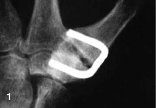
Historically, the first orthopedic application of a SMA was a Nitinol Harrington instrument for scoliosis treatment that was introduced in 1976 by Schmerling (80), which enabled the surgeon to restore any relaxed corrective force postoperatively simply by the external application of heat. In addition, it could be used initially to apply a more appropriate set of corrective forces. Figure 17 shows an example of a Ni–Ti shape memory clamp in small bone surgery (81). Six months after surgery, a non-union was present, although the outcome in this patient was assessed as good.
CONCLUSIONS
A shape memory alloy is a metallic substance that has a memory for shape combined with superelasticity. The mechanisms of a nickel–titanium alloy’s shape memory effect and superelasticity are described based on thermally induced or stress induced martensite phase transformations. Some of the physical properties of nickel–titanium alloys and a phase diagram are included for reference. The thermomechanical characteristics, corrosion properties, and biocompatibility of Ni–Ti shape memory alloys are reviewed for the design of shape memory devices. Manufacturing methods, including refining, processing, shape memory programming, and transformation temperature range measuring methods are summarized for practical applications. Finally, some applications in medical devices are reviewed as examples of current trends in the use of shape memory alloys. In conclusion, Ni–Ti shape memory alloys are a very useful biocompatible material because of
Figure 17. Failed arthrodesis of the carpometacarpal joint when only one titanium–nickel (TiNi) clamp was used (81). (From Arch. Orthop. Trauma Surg., Vol. 117, 1998. Figure 1 on page 342, Musialek J., Filip P. and Nieslanik J. Reproduced with kind permission of Springer Science and Business Media.)
their unique mechanical properties and good corrosion resistance. A better understanding of shape memory alloys should allow further developments in this area.
BIBLIOGRAPHY
Cited References
1.Properties and selection. Metal handbook 8th edition volume 1. American Society for Metals; 1961. p 1.
2.Jena AK, Chaturvedi MC. Phase transformation in materials. Prentice Hall; 1992. p 1–3.
3.Park JB, Kim YK. Metallic biomaterials. In: Bronzino JD, editor. The biomedical engineering handbook. 2nd ed. Volume 1, CRC Press; 2000. p 37-1–37-20.
4.Buehler WJ, Gilfrich JV, Wiley RC. Effect of low-temperature phase changes on the mechanical properties of alloys near composition TiNi. J Appl Phys 1963;34:1475–1477.
5.Wayman CM, Duerig TW. An introduction to martensite and shape memory. In: Duerig TW, Melton KN, Stoeckel D, Wayman CM, editors. Engineering aspects of shape memory alloys. Butterworth-Heinemann; 1990. p 3–20.
6.Wang FE, Buehler WJ, Pickart SJ. Crystal structure and a unique martensite transition on TiNi. J Appl Phys 1965;36: 3232–3239.
7.Ling CH, Kaplow R. Stress-induced shape changes and shape memory in the R and Martensite transformations in equiatomic NiTi. Metal Trans A 1981;12A:2101–2111.
8.In: Nishiyama Z, Fine ME, Meshii M, Wayman CM, editors. Martensitic Transformation. London: Academic Press; 1978. p 1–13.
9.Kim YK. Thermo-mechanical study of annealed and laser heat treated nickel–titanium alloy dental arch wire. Ph.D. dissertation, University of Iowa, Iowa, Dec. 1989.
10.Wayman CM, Bhadeshia H. Phase transformations, Nondiffusive. In: Cahn RW, Haasen P, editor. Physical Metallurgy. 4th ed. Volume 2, North-Holland: 1996. p 1507–1554.
11.Wang FE, Pickart SJ, Alperin HA. Mechanism of the TiNi transformation and the crystal structures of TiNi-II and TiNiIII phases. J Appl Phys 1972;43:97–112.
12.Otsuka K, Wayman CM, Nakai K, Sakamoto H, Shimizu K. Superelasticity effects and stress-induced martensite transformations in Cu–Al–Ni alloys. Acta Metallurgica 1976;24: 207–226.
13.Kim YK, Doo JK, Park JP. The application of shape memory alloy to abdominoscopic suture needles, In: Shin KS, Yoon JK, Kim SJ, editors. Proceeding of 2nd Pacific RIM International conference on Advanced Materials and Processing. Korean Institue of Metals and Materials; 1995. p 1691–1696.
14.Oelander A. Z Kristallogr 1932;83A:145. as cited in Lieberman DS. Crystal geometry and mechanisms of phase transformations in crystalline solids. In: Aaronson HI, editor. Phase Transformations. American Society for Metals; 1970. p 1–58.
15.Greninger AB, Mooradian VG. Strain transformation in metastable beta copper-zinc and beta copper-tin alloys. Am Inst Mining Met Eng 1937;19:867.
16.Bush RE, Leudeman RT, Gross PM. Alloys of improved properties. AMRA CR 65-02/1, AD629726, U.S. Army Materials Research Agency, 1966.
17.Kurdjumov GV, Khandros LG. Dokl Akad Nauk SSSR 1949;66:211. (as cited in Delaey L, Krishnan RV, Tas H, Warlimont H. Review: thermoelasticity, pseudoelasticity and memory effects associated with martensitic transformations. J Mater Sci 1974;9:1521–1535.
18.Delaey L, Krishnan RV, Tas H, Warlimont H. Review Thermoelasticity, pesudoelasticity and the memory effects associated
with martensitic transformations Part 1 Structural and microstructural changes associated with the transformations. J Mat Sci 1974;9:1521–1535.
19.Krishnan RV, Delaey L, Tas H, Warlimont H. Review Thermoelasticity, pesudoelasticity and the memory effects associated with martensitic transformations Part 2 The macroscopic mechanical behaviour. J Mater Sci 1974;9:1536–1544.
20.Warlimont H, Delaey L, Krishnan RV, Tas H. Review Thermoelasticity, pesudoelasticity and the memory effects associated with martensitic transformations Part 3 Thermodynamics and kinetics. J Mater Sci 1974;9:1545–1555.
21.Melton KN. General applications of SMA’s and smart materials. In: Duerig TW, Melton KN, Stoeckel D, Wayman CM, editors. Engineering aspects of shape memory alloys. Butter- worth-Heinemann; 1990. p 220–239.
22.Miayazaki S. Medical and dental applications of shape memory alloys, In: Duerig TW, Melton KN, Stoeckel D, Wayman CM, editor. Engineering aspects of shape memory alloys. Butterworth-Heinemann; 1990. p 267–281.
23.Filip P. Titanium-Nickel shape memory alloys in medical applications. In: Brunette DM, Tengvall P, Textor M, Thomsen P, editor. Titanium in Medicine. Springer; 2001. p 53–86.
24.Andreasen GF, Hilleman TB. An evaluation of 55 cobalt substituted Nitinol wire for use in orthodontics. JADA 1971;82: 1373–1375.
25.Dotter CT, Bushmann RW, McKinney MK, Rosch J. Transluminal expandable nitinol coil stent grafting: preliminary report. Radiology 1983;147:259–260.
26.Cragg A, Lund G, Rysavy J, Castaneda F, Castaneda-Zuniga W, Amplatz K. Nonsurgical placement of arterial endoprostheses: a new technique using nitinol wire. Radiology 1983;147: 261–263.
27.Ro¨sch J, Keller FS, Kaufman JA. The Birth, Early Years, and Future of Interventional Radiology. JVIR 2003;14(7):841–853.
28.Rauber K, Franke C, Rau WS, Syed Ali S, Bensmann G. Perorally insertable endotracheal stents made from NiTi memory alloy - an experimental animal study. Rofo Fortschr Geb Rontgenstr Neuen Bildgeb Verfahr 1990;152(6):698–701.
29.Rabkin JE, Germashev V. The Rabkin nitinol coil stent: a fiveyear experience. In: Castaneda-Zuniga WR, Tadavarthy SM, editors. Interventional Radiology, 2nd ed. Williams & Wilkins; 1992. p 576–581.
30.Kikuchi Y, Graves VB, Strother CM, McDermott JC, Babel SG, Crummy AB. A new guidewire with kink-resistant core and low-friction coating. Cardiovasc Intervent Radiol 1989;12(2): 107–109.
31.Kauffman GB, Mayo I. The story of Nitinol: the serendipitous discovery of the memory metal and its applications. Chem Educator 1997;2(2):S1430–4171; http://chemeducator.org/ bibs/0002002/00020111.htm, Feb.2. 2005.
32.Castleman LS, Motzkin SM. The Biocompatibility of Nititnol. In: Williams DF, editor. Biocompatibility of Clinical Implant Materials volume I. CRC Press; 1981. p 129–154.
33.Cross WB, Karitos AH, Wasilewski RJ. Nitinol characterization study. NASA CR-1433, National Aeronautics and Space Administration, Houston. 1969.
34.Buehler WJ, Wiley RC. TiNi-ductile intermetallic compound. Trans ASM 1962;55:269–276.
35.Otsuka K, Kakeshita T. Science and Technology of Shape memory Alloys: New Developments. MRS Bull 2002;27(2): 91–100.
36.Kim YK. The study of the shape recovery temperature change of cold-worked nickel-titanium alloys. Inje J 1994;10(1): 341–352.
37.Aboelfotoh MO, Aboelfotoh HA, Washburn J. Observations of pretransformation lattice instability in near equiatomic NiTi alloy. J Appl Phys 49(10): 1978; 5230–5232.
ALLOYS, SHAPE MEMORY |
11 |
38.Ling HC, Kaplow R. Phase transitions and shape memory in NiTi. Metal Trans A 1980;11A:77–83.
39.Chandra K, Purdy GR. Obseravation of thin crystals of TiNi in premartensite states. J Appl Phys 19(5): 1968; 2176–2181.
40.Shin SH. The study of heat-treatment temperature effect on hardness and compressional properties of nickel-titanium alloy. Master. dissertation, Inje University, Korea, Dec. 1998.
41.Burkart MW, Read TA. Trans Met Soc AIME 1953;197:1516. (as cited in Krishnan RV, Delaey L, Tas H, Warlimont H. Review Thermoelasticity, pesudoelasticity and the memory effects associated with martensitic transformations Part 2 The macroscopic mechanical behaviour. J Mat Sci 1974;9:1536–1544.
42.Andreasen GF, Fahl JL. Alloys, Shape Memory. In: Webster JG, editor. Encyclopedia of Medical Devices and Instrumentation. Volume 1, New York: Wiley-Interscience; 1988. p 15–20.
43.Thierry B, Merhi Y, Bilodeau L, Trepanier C, Tabrizian M. Nitinol versus stainless steel stents: acute thrombogenicity study in an ex vivo porcine model. Biomaterials 2002;23:2997– 3005.
44.Moberly WJ, Melton KN. Ni–Ti–Cu shape memory alloys. Engineering Aspects of Shape Memory Alloys. London: But- terworth-Heinemann; 1990. p 46–57.
45.Murakami Y, Asano N, Nakanishi N, Kachi S. Phase relation and kinetics of the transformations in Au–Cu–Zn thernary alloys. Jpn J Appl Phys 1967;6:1265–1271.
46.Gil FJ, Planell JA. Effect of copper addition on the superelastic behavior of Ni–Ti shape memory alloys for orthodontic applications. J Biomed Mater Res Appl Biomat 1999;48:682–688.
47.Goldstein D, Kabacoff L, Tydings J. Stress effects on Nitinol phase transformations. J Metals 1987;39(3):19–26.
48.Lee JH, Park JB, Andreasen GF, Lakes RS. Thermo mechanical study of Ni–Ti alloys. J Biomed Mater Res 1988;22: 573–588.
49.Kim YK. The Grain size distribution study of heat treated Ni–Ti alloy. Inje J 1993;9(2):857–868.
50.Differential Scanning Calorimetry, Dept. of Polymer Science, University of Southern Mississippi. Available at http:// www.psrc.usm.edu/macrog/dsc.htm. Accessed Feb. 8. 2005.
51.Harrison JD. Measurable changes concomitant with the shape memory effect transformation, In: Duerig TW, Melton KN, Stoeckel D, Wayman CM, editors. Engineering aspects of shape memory alloys. Butterworth-Heinemann; 1990. p 106–111.
52.Wang FE, DeSavage BF, Buehler WJ, Hosler WR. The irreversible critical range in the TiNi transition. J Appl Phys 1968;39(5):2166–2175.
53.Kim YK. unpublished experimental data (ykkimbme.inje.ac.kr).
54.Cutright DE, Bhaskar SN, Perez B, Johnson RM, Cowan GS, Jr. Tissue reaction to nitinol wire alloy. Oral Surg 1973;35(4): 578–584.
55.Castleman LS, Motzkin SM, Alicandri FP, Bonawit VL. Biocompatibility of Nitinol alloy as an implant material. J Biomed Mater Res 1976;10:695–731.
56.Castleman LS, Motzkin SM. The biocompatibility of Nitinol. In: Williams DF, editor. Biomcompatibility of Clinical Implant Materials. Volume 1, CRC Press; 1981. p 129–154.
57.Park JB. Metallic implant materials. Biomaterials Science and Engineering. Joon Bu Park: Plenum Press; 1984. p 193–233.
58.Ryhaenen J. Biocompatibility Evaluation of Nickel-Titanium Shape Memory Metal Alloy. Academic Dissertation, University hospital of Oulu, on May 7th, 1999.
59.Trepanier C, Tabrizian M, Yahia LH, Bilodeau L, Piron DL. Effect of modification of oxide layer on NiTi stent corrosion resistance. J Biomed Mater Res (Appl Biomater) 1998;43:433–440.
60.Kammula RG, Morris JM. Considerations for the Biocompatibility Evaluation of Medical Devices. Available at http:// www.devicelink.com/mddi/archive/01/05/008.html. Medical Device Link. Accessed Feb. 2. 2005.