

- •VOLUME 1
- •CONTRIBUTOR LIST
- •PREFACE
- •LIST OF ARTICLES
- •ABBREVIATIONS AND ACRONYMS
- •CONVERSION FACTORS AND UNIT SYMBOLS
- •ABLATION.
- •ABSORBABLE BIOMATERIALS.
- •ACRYLIC BONE CEMENT.
- •ACTINOTHERAPY.
- •ADOPTIVE IMMUNOTHERAPY.
- •AFFINITY CHROMATOGRAPHY.
- •ALLOYS, SHAPE MEMORY
- •AMBULATORY MONITORING
- •ANALYTICAL METHODS, AUTOMATED
- •ANALYZER, OXYGEN.
- •ANESTHESIA MACHINES
- •ANESTHESIA MONITORING.
- •ANESTHESIA, COMPUTERS IN
- •ANGER CAMERA
- •ANGIOPLASTY.
- •ANORECTAL MANOMETRY
- •ANTIBODIES, MONOCLONAL.
- •APNEA DETECTION.
- •ARRHYTHMIA, TREATMENT.
- •ARRHYTHMIA ANALYSIS, AUTOMATED
- •ARTERIAL TONOMETRY.
- •ARTIFICIAL BLOOD.
- •ARTIFICIAL HEART.
- •ARTIFICIAL HEART VALVE.
- •ARTIFICIAL HIP JOINTS.
- •ARTIFICIAL LARYNX.
- •ARTIFICIAL PANCREAS.
- •ARTERIES, ELASTIC PROPERTIES OF
- •ASSISTIVE DEVICES FOR THE DISABLED.
- •ATOMIC ABSORPTION SPECTROMETRY.
- •AUDIOMETRY
- •BACTERIAL DETECTION SYSTEMS.
- •BALLOON PUMP.
- •BANKED BLOOD.
- •BAROTRAUMA.
- •BARRIER CONTRACEPTIVE DEVICES.
- •BIOCERAMICS.
- •BIOCOMPATIBILITY OF MATERIALS
- •BIOELECTRODES
- •BIOFEEDBACK
- •BIOHEAT TRANSFER
- •BIOIMPEDANCE IN CARDIOVASCULAR MEDICINE
- •BIOINFORMATICS
- •BIOLOGIC THERAPY.
- •BIOMAGNETISM
- •BIOMATERIALS, ABSORBABLE
- •BIOMATERIALS: AN OVERVIEW
- •BIOMATERIALS: BIOCERAMICS
- •BIOMATERIALS: CARBON
- •BIOMATERIALS CORROSION AND WEAR OF
- •BIOMATERIALS FOR DENTISTRY
- •BIOMATERIALS, POLYMERS
- •BIOMATERIALS, SURFACE PROPERTIES OF
- •BIOMATERIALS, TESTING AND STRUCTURAL PROPERTIES OF
- •BIOMATERIALS: TISSUE-ENGINEERING AND SCAFFOLDS
- •BIOMECHANICS OF EXERCISE FITNESS
- •BIOMECHANICS OF JOINTS.
- •BIOMECHANICS OF SCOLIOSIS.
- •BIOMECHANICS OF SKIN.
- •BIOMECHANICS OF THE HUMAN SPINE.
- •BIOMECHANICS OF TOOTH AND JAW.
- •BIOMEDICAL ENGINEERING EDUCATION
- •BIOSURFACE ENGINEERING
- •BIOSENSORS.
- •BIOTELEMETRY
- •BIRTH CONTROL.
- •BLEEDING, GASTROINTESTINAL.
- •BLADDER DYSFUNCTION, NEUROSTIMULATION OF
- •BLIND AND VISUALLY IMPAIRED, ASSISTIVE TECHNOLOGY FOR
- •BLOOD BANKING.
- •BLOOD CELL COUNTERS.
- •BLOOD COLLECTION AND PROCESSING
- •BLOOD FLOW.
- •BLOOD GAS MEASUREMENTS
- •BLOOD PRESSURE MEASUREMENT
- •BLOOD PRESSURE, AUTOMATIC CONTROL OF
- •BLOOD RHEOLOGY
- •BLOOD, ARTIFICIAL
- •BONDING, ENAMEL.
- •BONE AND TEETH, PROPERTIES OF
- •BONE CEMENT, ACRYLIC
- •BONE DENSITY MEASUREMENT
- •BORON NEUTRON CAPTURE THERAPY
- •BRACHYTHERAPY, HIGH DOSAGE RATE
- •BRACHYTHERAPY, INTRAVASCULAR
- •BRAIN ELECTRICAL ACTIVITY.
- •BURN WOUND COVERINGS.
- •BYPASS, CORONARY.
- •BYPASS, CARDIOPULMONARY.
94.Saneinejad S, Shoichet MS. Patterned poly(chlorotrifluoroethylene) guides primary nerve cell adhesion and neurite outgrowth. J Biomed Mater Res 2000;50(4):465–474.
95.Tai H, Buettner HM. Neurite outgrowth and growth cone morphology on micropatterned surfaces. Biotechnol Prog 1998;14:364–370.
96.Zhang ZP, Yoo R, Wells M, Beebe TP, Biran R, Tresco P. Neurite outgrowth on well-characterized surfaces: Preparation and characterization of chemically and spatially controlled fibronectin and RGD substrates with good bioactivity. Biomaterials 2005;26(1):47–61.
97.Heller DA, Garga V, Kelleher KJ, Lee TC, Mahbubani S, Sigworth LA, Lee TR, Rea MA. Patterned networks of mouse hippocampal neurons on peptide-coated gold surfaces. Biomaterials 2005;26(8):883–889.
See also BIOCOMPATIBLITY OF MATERIALS; BIOMATERIALS, SURFACE PROPERTIES OF; BIOMATERIALS: TISSUE ENGINEERING AND SCAFFOLDS.
BIOMEDICAL EQUIPMENT
MAINTENANCE. See EQUIPMENT MAINTENANCE,
BIOMEDICAL.
BIOSENSORS. See IMMUNOLOGICALLY SENSITIVE FIELD-
EFFECT TRANSISTORS.
BIOTELEMETRY
BABAK ZIAIE
Purdue University
W. Lafayette, Indiana
INTRODUCTION
The ability to use wireless techniques for measurement and control of various physiological parameters inside human and animal bodies has been a long-term goal of physicians and biologists going back to the early days of wireless communication. From early on, it was recognized that this capability could provide effective diagnostic, therapeutic, and prosthetic tools in physiological research and pathological intervention. However, this goal eluded scientists prior to the invention of transistor in 1947. Vacuum tubes were too bulky and power hungry to be of any use in many wireless biomedical applications. During the late 1950s, MacKay performed his early pioneering work on what he called Endoradiosonde (1). This was a singletransistor blocking oscillator designed to be swallowed by a subject and was able to measure pressure and temperature in the digestive track. Following this early work, came a number of other simple discrete systems each designed to measure a specific parameter (temperature, pressure, force, flow, etc.) (2). By the late 1960s, progress in the design and fabrication of integrated circuits provided an opportunity to expand the functionality of these early systems. Various hybrid single and multichannel telemetry systems were developed during the 1970s and the 1980s
(3). In addition, implantable therapeutic and prosthetic devices started to appear in the market. Cardiac pacemakers and cochlear prosthetics proved effective and reli-
BIOTELEMETRY 417
able enough to be implanted in thousands of patients. We direct the interested readers to several excellent reviews published over the past several decades summarizing these advances in their perspective time periods. These include a review article by W. H. Ko and M. R. Neuman in the Science covering the technologies available in the 1960s (4) and another similar paper by Topich covering the 1970s period
(5). Three subsequent reviews detailed the efforts in the 1980s (6–8) followed by the most recent article published in 1999 (9). An outdated, but classic reference book in biotelemetry, is by MacKay, which still can be used as a good starting point for some simple single channel systems and includes some ingenious techniques used by early investigators to gain remote physiological information (10).
The latter part of the 1990s witnessed impressive advances in microelectromechanical (MEMS) based transducer and packaging technology, new and compact power sources (high efficiency inductive powering and miniature batteries), and CMOS low power wireless integrated circuits that provided another major impetus to the development of biotelemetry systems (11–18). These advances have created new opportunities for increased reliability and functionality, which had been hard to achieve with pervious technologies. The term biotelemetry itself has been for most part superseded by Microbiotelemetry or Wireless Microsystems to denote these recent changes in technology. Furthermore, the burgeoning area of nanotechnology is poised to further enhance these capabilities beyond what have been achievable using current miniaturization techniques. This is particularly true in the biochemical sensing and chemical delivery areas and will undoubtedly have a major impact on the future generations of implantable biotelemetry microsystems.
This review article is intended to complement and expand the earlier reviews by emphasizing newer developments in the area of biomedical telemetry in particular attention is paid to the opportunities created by recent advances in the area of microbiotelemetry (i.e., systems having volumes 1 cm3 or less) by low power CMOS wireless integrated circuits, micromachined–MEMS transducers, biocompatible coatings, and advanced batch-scale packaging. We have both expanded and narrowed the traditional definition of biotelemetry by including therapeutic– rehabilitative microsystems and excluding wired devices that although fit under the strict definition of biotelemetry; do not constitute an emerging technology. In the following sections, after discussing several major components of such biotelemetry microsystems, such as transducers, interface electronics, wireless communication, power sources, and packaging, we will present some selected examples to demonstrate the state of the art. These include implantable systems for biochemical and physiological measurements, drug delivery microsystems, and neuromuscular and visual prosthetic devices. Although our primary definition of biotelemetry encompass devices with active electronics and signal processing capabilities, we will also discuss passive MEMS-based transponders that do not require on-board signal processing and can be interrogated using simple radio-frequency (rf) techniques. Finally, we should mention that although in a strict sense biotelemetry encompasses systems targeted for physiological measurements, this
418 BIOTELEMETRY
narrow definition is no longer valid or desirable. A broader scope including neuromuscular stimulation and chemical delivery is currently understood to be more indicative of the term biotelemetry.
BIOTELEMETRY SYSTEMS
For the purpose of current discussion biotelemetry systems can be defined as a group of medical devices that (1) incorporate one or several miniature transducers (i.e., sensors and actuators), (2) have an on-board power supply (i.e., battery) or are powered from outside using inductive coupling, (3) can communicate with outside (bidirectional or unidirectional) through an rf interface, (4) have on-board signal processing capability, (5) are constructed using biocompatible materials, and (6) use advanced batch-scale packaging techniques. Although one microsystem might incorporate all of the above components, the demarcation line is rather fluid and can be more broadly interpreted. For example, passive MEMS-based microtransponders do not contain on-board signal processing capability, but use advanced MEMS packaging and transducer technology and are usually considered to be a telemetry device. We should also emphasize that the above components are interrelated and a good system designer must pay considerable attention from the onset to this fact. For example, one might have to choose a certain power source or packaging scheme to accommodate the desired transducer, interface electronics, and wireless communication. In the following sections, we will discuss various components of a typical biotelemetry system with more attention being paid to the wireless communication block. For other components, we provide a brief discussion highlighting major recent developments and refer the reader to some recent literature is these areas.
Transducers
Transducers are interfaces between biological tissue and readout electronics–signal processing. Their performance is critical to the success of the overall microsystem (19–24). Current trend in miniaturization of transducers and their integration with signal processing circuitry have considerably enhanced their performance. This is particularly true with respect to MEMS-based sensors and actuators, where the advantages of miniaturization have been prominent. Development in the area of microactuators has been lagging behind the microsensors due to the inherent difficulty in designing microdevices that efficiently and reliably generate motion. Although some transducing schemes, such as electrostatic force generation, has advantageous scaling properties in the microdomain, problems associated with packaging and reliability has prevented their successful application. The MEMS-based microsensors have been more successful and offer several advantages compared to the macrodomain counterparts. These include lower power consumption, increased sensitivity, higher reliability, and lower cost due to batch fabrication. However, they suffer from a poor signal/noise ratio, hence requiring a close by interface circuit. Among the many microsensors designed and fabricated over the past two decades, physical sensors have been by and large more successful. This is due to their
inherent robustness and isolation from any direct contact with biological tissue in sensors, such as accelerometers and gyroscopes. Issues related to packaging and long-term stability have plagued the implantable chemical sensors. Longterm baseline and sensitivity stability are major problems associated with implantable sensors. Depending on the type of the sensor, several different factors contribute to the drift. For example, in implantable pressure sensors, packaging generated stresses due to thermal mismatch and long-term material creep are the main sources of baseline drift. In chemical sensors, biofouling and fibrous capsule formation is the main culprit. Some of these can be mitigated through clever mechanical design and appropriate choice of material, however, some are more difficult to prevent (e.g., biofouling and fibrous capsule formation). Recent developments in the area of antifouling material and controlled release have provided new opportunities to solve some of these long standing problems (25–27).
Interface Electronics
As mentioned previously, most miniature and MEMSbased transducers suffer from poor signal/noise ratio and require on-board interface electronics. This, of course, is also more essential for implantable microsystems. The choice of integrating the signal processing with the MEMS transducer on the same substrate or having a separate signal processing chip in close proximity depends on many factors, such as process complexity, yield, fabrication costs, packaging, and general design philosophy. Except for postCMOS MEMS processing methods, which rely on undercutting micromechanical structures subsequent to the fabrication of the circuitry (28), other integrated approaches require extensive modifications to the standard CMOS processes and have not been able to attract much attention. Post-CMOS processing is an attractive approach although packaging issues still can pose roadblocks to successful implementation. Hybrid approach has been typically more popular with the implantable biotelemetry microsystem designers providing flexibility at a lower cost. Power consumption is a major design consideration in implantable wireless microsystems that rely on batteries for an energy source. Low power and subthreshold CMOS design can reduce the power consumption to nanowatt levels (29–33). Important analogue and mixed-signal building blocks for implantable wireless microsystems include amplifiers, oscillators, multiplexers, A/D and D/A converters, and voltage references. In addition, many such systems require some digital signal processing and logic function in the form of finite-state machines. In order to reduce the power consumption, it is preferable to perform the DSP functions outside the body although small finite-state machines can be implemented at low power consumptions.
Wireless Communication
The choice of appropriate communication scheme for a biotelemetry system depends on several factors, such as (1) number of channels, (2) device lifetime, and (3) transmission range. For single (or two) channel systems, one can choose a variety of modulation schemes and techniques.
These systems are the oldest type of biotelemetry devices
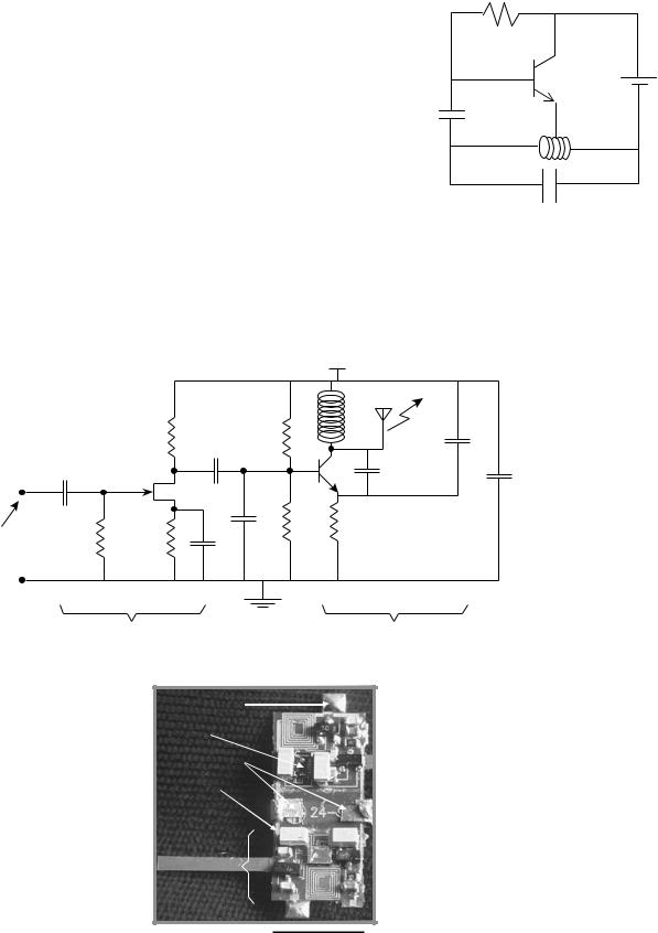
(1) and can range from simple blocking oscillators to single channel frequency modulation (FM) transmitters. They are attractive since one can design a prototype rather quickly using off-the-shelf components. Figure 1 shows a schematic of the famous blocking oscillator first used by MacKay to transmit pressure and temperature (10). It consists of a single bipolar transistor oscillator configured to periodically turn itself on and off. The oscillation frequency depends on the resonant frequency of the tank circuit that can be made to vary with parameters, such as pressure, by including a capacitive or inductive pressure sensor. The on–off repetition frequency can be made to depend on the temperature by incorporating a thermistor in the circuit. This is an interesting example of an ingenious design that can be accomplished with a minimum amount of effort and hardware. An example of a more recent attempt at single channel telemetry is a two-channel system designed by Mohseni et al. to transmit moth electromyograms (34). The circuit schematic and a picture of the fully assembled device are shown in Fig. 2. As can be seen, each channel
BIOTELEMETRY 419
R Thermistor
VCC
C1
L
C2
Figure 1. Schematic circuit of a blocking oscillator used to transmit pressure and temperature.
|
|
|
|
Vcc |
|
|
|
|
|
Lt |
|
|
|
Rb |
Rb1 |
|
|
|
|
Cc2 |
|
|
C2 |
|
Cc1 |
|
|
T1 |
|
|
|
J1 |
|
C1 |
Cby |
|
|
|
|
||
|
|
|
Rb2 |
Re |
|
EMG |
Rg |
Rs |
Cb |
|
|
|
|
|
|||
|
|
Cs |
|
|
|
Biopotential amplifier |
FM transmitter |
Antenna Pad
RC Chip
Battery Clips
Polyimide
Substrate
One
Channel
1 cm
Figure 2. Schematic diagram and photograph of a biotelemetry system used to transmit flight muscle electromyograms in moths showing the polyimide flex circuit and various components (the Colpitts Oscillator inductor is used as the transmitting antenna).
420 BIOTELEMETRY
consists of a biopotential amplifier followed by a Colpitts oscillator with operating frequency tunable in the 88– 108 MHz commercial FM band. The substrate for the biotelemetry module was a polyimide flex circuit in order to reduce the weight such that the Moth can carry the system during flight. The overall system measures 10 10 3 mm, weighs 0.74 g, uses two 1.5 V batteries, dissipates 2 mW, and has a transmission range of 2 m.
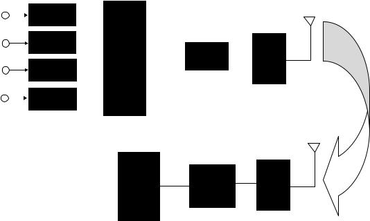
Multichannel systems are of more scientific and clinical interest. These systems rely on different and more elaborate communication schemes. For the purpose of current discussion, we will divide these systems into the ones that operate with a battery and the ones that are powered from outside using an inductive link. Battery-operated biotelemetry microsystems rely on different communication schemes than the inductively powered ones. Figure 3 shows a schematic block diagram of a time-division multiplexed multichannel system. It consists of several transducers with their associated signal conditioning circuits. These might include operations, such as simple buffering, low level amplification, filtering, or all three. Subsequent to signal conditioning, different channels are multiplexed using an analogue MUX. Although recent advances in AD technology might allow each channel to be digitized prior to multiplexing, this is not an attractive option for biotelemetry systems (unless there are only a few channels), since it requires an increase in power consumption that most biotelemetry systems cannot afford. All the timing and framing information is also added to the outgoing multiplexed signal at this stage. After multiplexing, an AD converter is used to digitize the signal. This is followed by a rf transmitter and a miniature antenna. The transmitted signal is picked up by a remote receiver and the signal is demodulated and separated accordingly. The described architecture is the one used currently by
most investigators. Although over the years many different modulation scheme (pulse-width-modulation, pulse-posi- tion-modulation, pulse-amplitude-modulation, etc.) and system architectures have been tried; due to the proliferation of inexpensive integrated low power AD converters, the pulse-code-modulation (PCM) using an integrated AD is the dominant method these days.
The transmission of the digitized signal can be accomplished using any of the several digital modulation schemes (PAM, PFM, QPSK, etc.), which offer standard trade offs between transmitter and receiver circuit complexity, power consumption, and signal/noise ratio (35). Typical frequencies used in such systems are in the lower UHF range (100–500 MHz). Higher frequencies result in smaller transmitter antenna at the expense of increased tissue loss. Although tissue loss is a major concern in transmitting power to implantable microsystems, it is less of an issue in data transmission, since a sensitive receiver outside the body can easily demodulate the signal. Recent advances in low power CMOS rf circuit design has resulted in an explosive growth of custom made Application Specific Integrated Circuits (ASIC), and off-the-shelf rf circuits suitable for a variety of biotelemetry applications (36– 38). In addition, explosive proliferation of wireless communication systems (cell phones, wireless PDAs, Wi-Fi systems, etc.) have provided a unique opportunity to piggyback major WLAN manufacturers and simplify the design of biotelemetry microdevices (39,40). This cannot only increase the performance of the system, but also creates a standard platform for many diverse applications. Although the commercially available wireless chips have large bandwidths and some superb functionality, their power consumption is higher than what is acceptable for many of the implantable microsystems. This, however, is going to change in the future by the aggressive move
Signal
Sensor 1 |
conditioning |
|
|
|
|
|
|
|
|
|
|
|
|
|
|
||
|
|
|
|
|
|
|
|
|
Sensor 2 |
Signal |
|
|
Analog |
|
|
|
|
conditioning |
|
|
|
|
|
|
||
Sensor 3 |
Signal |
|
|
Mux |
|
ADC |
|
XMTAR |
|
|
|
|
|||||
|
|
|
|
|
|
|
||
conditioning |
|
|
|
|
|
|
|
|
|
|
|
|
|
|
|
|
|
Sensor 4 |
Signal |
|
|
|
|
|
|
|
conditioning |
|
|
|
|
|
|
|
|
|
|
|
|
|
|
|
|
DAC
Display & RCVER decoder
Figure 3. Block diagram of a multichannel biotelemetry system.
toward lower power handheld consumer electronics. A particularly attractive WLAN system suitable for biotelemetry is the Bluetooth system (41). This system, which was initially designed for wireless connection of multiple systems (computer, fax, printer, PDA, etc.) located in close proximity, has been adopted by many medical device manufacturer for their various biotelemetry applications. The advantage of Bluetooth compared to other Wi-Fi system, such as 902.11-b, is its lower power consumption at the expense of a smaller data rate (2.4 GHz carrier frequency, 1 Mbps data rate, and 10 m transmission range). This is not critical in most biotelemetry applications since the frequency bandwidth of most physiologically important signals are low (<1 kHz). However, note that since the Bluetooth carrier frequency is rather high (2.4 GHz), the systems using Bluetooth or similar WLAN devices can not operate from inside the body and has to be worn by the subject on the outside.
Inductively powered telemetry systems differ from the battery operated ones in several important ways (42). First and foremost, the system has to be powered by an rf signal from outside; this puts several restrictions on frequency and physical range of operation. For implantable systems, the incoming signal frequency has to remain low in order for it to allow enough power to be coupled to the device (this means a frequency range of 1–10 MHz, see next section). In addition, if the device is small, due to a low coupling coefficient between the transmitter and receiver coil, the transmission range is usually limited to distances <10 cm. Finally, in inductively powered systems, one has to devise a method to transmit the measured signal back to the outside unit. This can be done in several different ways with the load-modula- tion being the most popular method (43). In ‘‘load modulation’’, the outgoing digital stream of data is used to load the receiver antenna by switching a resistor in parallel with the tank circuit. This can be picked up through the transmitter coil located outside the body. A second technique that is more complex requires an on-chip transmitter and a second coil to transmit the recorded data at a different frequency. The inward link can be easily implemented using amplitude modulation, that is, the incoming rf signal that powers the microsystem is modulated by digitally varying the amplitude. It is evident that the modulation index cannot be 100% since that would cut off the power supply to the device (unless a storage capacitor is used). The coding scheme is based on the pulse time duration, that is,‘‘1’’ and ‘‘0’’ have the same amplitude, but different durations (42). This modulation technique requires a simple detection circuitry (envelope detector) and is immune to amplitude variations, which are inevitable in such systems.
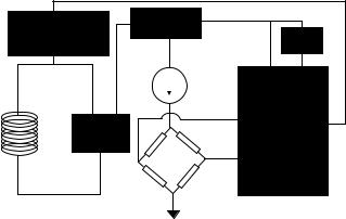
In addition to the above mentioned differences between the battery operated and inductively powered biotelemetry systems, the implanted circuit in the latter case also includes several modules that are unique and require special attention. These have mostly to do with power reception (rectifier and voltage regulator), clock extraction, and data demodulation. Figure 4 shows a block diagram of the receiver circuit for an inductively powered microsystem currently being developed in the author’s laboratory for the measurement of intraocular pressure in glaucoma patients. It consists of a full-bridge rectifier, a voltage
BIOTELEMETRY |
421 |
Load shift keying |
Regulator |
|
|
modulator |
Bias |
|
Voltag e to |
|
Time Converter |
Rectifier |
|
|
Sensor |
Figure 4. Block diagram of an implantable biotelemetry system used in the measurement of intraocular pressure in glaucoma patients.
regulator, a piezoresistive pressure sensor, and voltage to frequency converter. The incoming rf signal is first rectified and used to generate a stable voltage reference being used by the rest of the circuit (amplifiers, filters, etc.). The clock is extracted from the incoming rf signal and is used wherever it is needed in the receiver circuit. The pressure sensor bridge voltage is first amplified and converted to a stream of pulses having a frequency proportional to the pressure. This signal is then used to loadmodulate the tank circuit. The receiver circuitry for most of the reported inductively powered biotelemetry systems were fabricated through CMOS foundries, such as MOSIS. This is due to the fact that one can simply design a single chip performing all of the mentioned functions in a CMOS technology, and hence save valuable space. In the sections dealing with various applications, we will describe several other inductively powered telemetry systems.
There has not been much effort in the area of antenna design for biotelemetry applications. This is due to the basic fact that these systems are small and operate at low frequencies, hence, most antennas employed in such systems belong to the‘‘small antenna’’ category, that is, the antenna size is much smaller than the wavelength. In such cases it is difficult to optimize the design and most investigators simply use a short electrical or magnetic dipole. For example, in many situations the inductor in the output stage can be used to transmit the information. Or alternatively, a short wire can be used in the transmitter as an electrical dipole. These antennas are usually low gain and have an omnidirectional pattern (44). Systems operating at higher frequencies, such as externally worn Wi-Fi modules, however, can benefit from an optimized design.
In addition to using an rf signal to transmit information that constitutes the majority of the work in the biotelemetry area, the use of ultrasound and infrared (IR) have also been explored by some investigators (45,46). The use of ultrasound is attractive in telemetering physiological information from aquatic animals and divers. This is due to the fact that rf signals are strongly absorbed by seawater while ultrasound is not affected to the same extent. The use of IR is also limited to some specific areas, such as systems that can be worn by the animal on the outside and are not
422 BIOTELEMETRY
impeded by solid obstructions. This is due to the inability of IR to negotiate solid opaque objects (line of sight propagation) and its severe absorption by tissue. The advantage of free space IR transmission lies in its very wide bandwidth making it useful for transmitting neural signals. The rf, ultrasonic, and IR systems share many of the system components discussed so far, with the major difference between them having to do with the design and implementation of the output stage. The output transmitter for the ultrasonic biotelemetry systems is usually an ultrasonic transducer, such as PZT or PVDF, whereas for the IR systems it is usually a simple light-emitting diode (LED). The driver circuitry has to be able to accommodate the transducers, that is, a high voltage source for driving the ultrasonic element and a current.
Power Source
The choice of power source for implantable wireless microsystems depends on several factors, such as implant lifetime, system power consumption, temporal mode of operation (continuous or intermittent), and size. Progress in battery technology is incremental and usually several generations behind other electronic components (47). Although lithium batteries have been used in pacemakers for several years, they are usually large for microsystem applications. Other batteries used in hearing aids and calculators are smaller, but have limited capacity and can only be used for low power systems requiring limited lifespan or intermittent operation. Inductive powering is an attractive alternative for systems with large power requirements (e.g., neuromuscular stimulators) or long lifetime (e.g., prosthetic systems with >5 years lifetime) (14,15). In such systems, a transmitter coil is used to power a microchip using magnetic coupling. The choice of the transmission frequency is a trade-off between adequate miniaturization and tissue loss. For implantable microsystems, the frequency range of 1–10 MHz is usually considered optimum for providing adequate miniaturization while still staying below the high tissue absorption region (>10 MHz) (48). Although the link analysis and optimization methods have been around for many years (49), recent integration techniques that allow the fabrication of microcoils on top of CMOS receiver chip has allowed a new level of miniaturization (50). For applications that require the patient to carry the transmitter around, a high efficiency transmitter is needed in order to increase the battery lifetime. This is particularly critical in implantable microsystem, where the magnetic coupling between the transmitter and the receiver is low (<1%). Class-E power amplifier/transmitters are popular among microsystem designers due to their high efficiency (>80%) and relatively easy design and construction (51,52). They can also be easily amplitude modulated through supply switching.
Although ideally one would like to be able to tap into the chemical reservoir (i.e., glucose) available in the body to generate enough power for implantable microsystems (glucose-based fuel cell), difficulty in packaging and low efficiencies associated with such fuel cells have prevented their practical application (53). Thin-film batteries are also attractive, however, there still remain numerous material
and integration difficulties that need to be resolved (54). Another alternative is nuclear batteries. Although they have been around for several decades and were used in some early pacemakers, safety and regulatory concerns forced medical device companies to abandon their efforts in this area. There has been a recent surge of interest in microsystem nuclear batteries for military applications (55). It is not hard to envision that due to the continuous decrease in chip power consumption and improve in batch scale MEMS packaging technology, one might be able to hermetically seal a small amount of radioactive source in order to power an implantable microsystem for a long period of time. Another possible power source is the mechanical movements associated with various organs. Several proposals dealing with parasitic power generation through tapping into this energy source have been suggested in the past few years (56). Although one can generate adequate power from activities, such as walking, to power an external electronic device, difficulty in efficient mechanical coupling to internal organ movements make an implantable device hard to design and utilize.
Packaging and Encapsulation
Proper packaging and encapsulation of biotelemetry microsystems is a challenging design aspect particularly if the device has to be implanted for a considerable period. The package must accomplish two tasks simultaneously: (1) protect the electronics from the harsh body environment while providing access windows for transducers to interact with the desired measurand, and (2) protect the body from possible hazardous material in the microsystem. The second task is easier to fulfill since there is a cornucopia of various biocompatible materials available to the implant designer (57). For example, silicon and glass, which are the material of choice in many MEMS applications, are both biocompatible. In addition, polydimethylsiloxane (PDMS) and several other polymers (e.g., polyimide, polycarbonate, parylene) commonly used in microsystem design are also accepted by the body. The first requirement is, however, more challenging. The degree of protection required for implantable microsystems depends on the required lifetime of the device. For short durations (several months), polymeric encapsulants might be adequate if one can conformally deposit them over the substrates (e.g., plasma deposited parylene) (58). These techniques are considered non-hermetic and have a limited lifetime. For long-term operation, hermetic sealing techniques are required (59). Although pacemaker and defibrillator industries have been very successful in sealing their systems in tight titanium enclosures; these techniques are not suitable for microsystem applications. For example a metallic enclosure prevents the transmission of power and data to the microsystem. In addition, these sealing methods are serial in nature (e.g., laser or electron beam welding) and are not compatible with integrated batch fabrication methods used in microsystem design. Silicon–glass electrostatic and sili- con–silicon fusion bonding are attractive methods for packaging implantable microsystems (60). Both of these bonding methods are hermetic and can be performed at the wafer level. These are particularly attractive for
|
External telemeteric |
|
|
External coil |
components |
|
|
Spectacles |
Cable to hand-held-unit |
||
|
Pressure sensor,
internal telemetric components
 Eye
Eye
Artificial intraocular lens
Figure 5. Schematic of the IOP measurement microsystem (61).
inductively powered wireless microsystems since most batteries cannot tolerate the high temperatures required in such substrate bondings. Other methods, such as metal electroplating, have also been used to seal integrated MEMS microsystems. However, their long-term performance is usually inferior to the anodic and fusion bondings. In addition to providing a hermetic seal, the package must allow feeedthrough for transducers located outside the package (18). In macrodevices, such as pacemakers, where the feedthrough lines are large and not too many, traditional methods, such as glass–metal or ceramic–metal has been employed for many years. In microsystems, such methods are not applicable and batch scale techniques must be adopted.
DIAGNOSTIC APPLICATIONS
Diagnostic biotelemetry microsystems are used to gather physiological or histological information from within the body in order to identify pathology. Two recent examples are discussed in this category. The first is a microsystem designed to be implanted in the eye and to measure the intraocular pressure in order to diagnose low tension glaucoma. The second system, although not strictly implanted, is an endoscopic wireless camera-pill designed to be swallowed in order to capture images from the digestive track.
Figure 5 shows the schematic diagram of the intraocular pressure (IOP) measurement microsystem (61,62). This device is used to monitor the IOP in patients suffering from low tension glaucoma, that is, the pressure measured in the doctor’s office is not elevated (normal IOP is 10–20 mmHg, 1.33–2.66 kPa) while the patient is showing optic nerve degeneration associated with glaucoma. There is great interest in measuring the IOP in such patients during their normal course of daily activity (exercising, sleeping, etc). This can only be achieved using a wireless microsystem. The system shown in Fig. 5 consists of an external transmitter mounted on a spectacle, which is used to power a microchip implanted in the eye. A surface micromachined capacitive pressure sensor integrated with CMOS interface circuit is connected to the receiving antenna. The receiver chip implemented in an n-well 1.2 mm CMOS technology has overall dimensions of 2.5 2.5 mm2 and consumes 210 mW (Fig. 6). The receiver polyimide-based antenna is, however, much
BIOTELEMETRY 423
Figure 6. Micrograph of the IOP measurement microsystem receiver chip showing surface micromachined capacitive pressure sensors and other parts of the receiver circuitry (62).
larger (1 cm in diameter and connected to the receiver using flip chip bonding) requiring the device to be implanted along with an artificial lens. The incoming signal frequency is 6.78 MHz, while the IOP is transmitted at 13.56 MHz using load-modulation scheme. This example illustrates the levels of integration that can be achieved using low power CMOS technology, surface micromachining, and flip chip bonding.
The second example in the category of diagnostic microsystems is an endoscopic wireless pill shown in Fig. 7 (63,64). This pill is used to image small intestine, which is a particularly hard area to reach using current fiber optic technology. Although these days colonoscopy and gastroscopy are routinely performed, they cannot reach the small intestine and many disorders (e.g., frequent bleeding) in this organ have eluded direct examination. A wireless endoscopic pill cannot only image the small intestine, but also will reduce the pain and discomfort associated with regular gastrointestinal endoscopies. The endoscopic pill is a perfect example of what can be called Reemerging Technology, that is, the rebirth of an older technology based on new capabilities offered by advances in modern technology. Although the idea of a video pill is not new, before the development of low power microelectronics, white LED, CMOS image sensor, and wide-band wireless communication, fabrication of such a device was not feasible. The video pill currently marketed by Given Imaging Inc. is 11 mm in diameter and 30 mm in length (size of a large vitamin tablet) and incorporates: (1) a short focal length lens, (2) a CMOS image sensor (90,000 pixel), (3) four white LEDs, (4) a low power ASIC transmitter, and (5) two batteries (enough to allows the pill to go though the entire digestive track). The pill can capture and transmit
424 BIOTELEMETRY
Figure 7. A photograph (a) and internal block diagram (b) of Given Imaging wireless endoscopic pill. (Courtesy Given Imaging.)
two images per second to an outside receiver capable of storing up to 5 h of data.
THERAPEUTIC APPLICATIONS
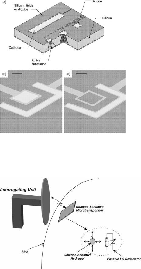
Therapeutic biotelemetry microsystems are designed to alleviate certain symptoms and help in the treatment of a disease. In this category, two such biotelemetry microsystems unit be described. The first is a drug delivery microchip designed to administer small quantities of potent drugs upon receiving a command signal from the outside. The second device is a passive micromachined glucose transponder, which can be used to remotely monitor glucose fluctuations allowing a tighter blood glucose control through frequent measurements and on-demand insulin delivery (pump therapy or multiple injections).
Figure 8 shows the central component of the drug delivery microchip (65,66). It consists of several microreservoirs (25 nL in volume) etched in a silicon substrate. Each microreservoir contains the targeted drug and is covered by a thin gold membrane (0.3 mm), which can be
dissolved through the application of a small voltage (1 V vs. Saturated Calomel Electrode). The company marketing this technology (MicroCHIPS Inc.) is in the process of designing a wireless transceiver that can be used to address individual wells and release the drug upon the reception of the appropriate signal (67). Another company (ChipRx Inc.) is also aiming to develop a similar microsystem (Smart Pill) (68). Their release approach, however, is different and is based on conductive polymer actuators acting similar to a sphincter, opening and closing a tiny reservoir. Due to the potency of many drugs, safety and regulatory issues are more stringent in implantable drug delivery microsystems and will undoubtedly delay their appearance in the clinical settings.
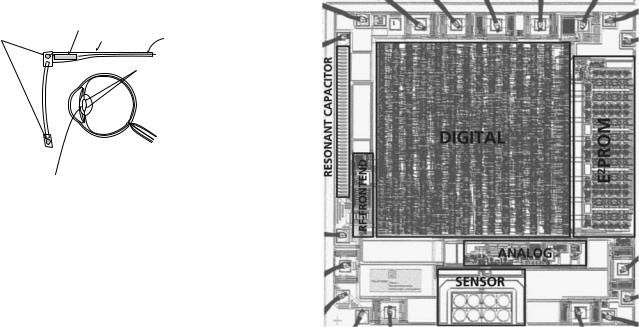
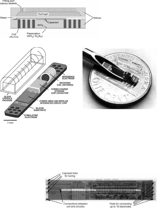
Figure 9 shows the basic concept behind the glucosesensitive microtransponder (69). A miniature MEMSbased microdevice is implanted in the subcutaneous tissue and an interrogating unit remotely measures the glucose levels without any hardwire connection. The microtrasponder is a passive LC resonator, which is coupled to a glucose-sensitive hydrogel. The glucose-dependent swelling and deswelling of the hydrogel is coupled to the resonator causing a change the capacitor value. This change translates into variations of the resonant frequency, which can be detected by the interrogating unit. Figure 10 shows the schematic drawing of the microtransponder with a capacitive sensing mechanism. The glucose sensitive hydrogel is mechanically coupled to a glass membrane and is separated from body fluids (in this case interstitial fluid) by a porous stiff plate. The porous plate allows the unhindered flow of water and glucose while blocking the hydrogel from escaping the cavity. A change in the glucose concentration of the external environment will cause a swelling or deswelling of the hydrogel, which will deflect the glass membrane and change the capacitance. The coil is totally embedded inside the silicon and can achieve a high quality factor and hence increased sensitivity by utilizing the whole wafer thickness (reducing the series resistance). The coil-embedded silicon and the glass substrate are hermetically sealed using glass–silicon anodic bonding.
REHABILITATIVE MICROSYSTEMS
Rehabilitative biotelemetry microsystems are used to substitute a lost function, such as vision, hearing, or motor activity. In this category, two microsystems are described. The first one is a single-channel neuromuscular microstimulator used to stimulate paralyzed muscle groups in paraplegic and quadriplegic patients. The second microsystem is a visual prosthetic device designed to stimulate ganglion cells in retina in order to restore vision to people afflicted with macular degeneration or retinitis pigmentosa.
Figure 11 shows a schematic of the single channel microstimulator (13). This device is 10 2 2 mm3 in dimensions and receives power and data through an inductively coupled link. It can be used to stimulate paralyzed muscle groups using thin-film microfabricated electrodes located at the ends of a silicon substrate. A hybrid capacitor
BIOTELEMETRY 425
is used to store the charge in between the stimulation pulses and to deliver 10 mA of current to the muscle every 25 ms. A glass capsule hermetically seals a BiCMOS receiver circuitry along with various other passive components (receiver coil and charge storage capacitor) located
Figure 8. MicroCHIP drug delivery chip (a), a reservoir before and after dissolution of the gold membrane (b,c), the bar is 50 mm (65).
on top of the silicon substrate. Figure 12 shows a photograph of the microstimulator in the bore of a gauge 10 hypodermic needle. As can be seen, the device requires a complicated hybrid assembly process in order to attach a wire-wound coil and a charge storage capacitor to the
Figure 9. Basic concept behind the glucose-sensitive microtransponder.
426 BIOTELEMETRY
Figure 11. Schematic of a single-channel implantable neuromuscular microstimulator.
receiver chip. In a subsequent design targeted for direct peripheral nerve stimulation (requiring smaller stimulation current), the coil was integrated on top of the BiCMOS electronics and on-chip charge storage capacitors were used thus considerably simplifying the packaging process. Figure 13 shows a micrograph of the chip with the electroplated copper inductor (70). A similar microdevice (i.e., a
Figure 13. Microstimulator chip with integrated receiver coil and on-chip storage capacitor (70).
Figure 10. Cross-section of glucose microtransponder.
Figure 12. Photograph of the microstimulator in the bore of a gage 10 hypodermic needle.
single channel microstimulator) was also developed by another group of investigators with the differences mainly related to the packaging technique (laser welding of a glass capsule instead of silicon–glass anodic bonding), chip technology (CMOS instead of BiCMOS), and electrode material (tantalum and iridium instead of iridium oxide) (42). Figure 14 shows a photograph of the microstimulator developed by Troyk, Loeb, and their colleagues.
Figure 15 shows the schematic of the visual prosthetic microsystem (71,72). A spectacle mounted camera is used to capture the visual information followed by digital conversion and transmission of data to a receiver chip
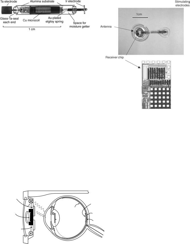
Figure 14. Photograph of a single channel microstimulator developed by Troyk (42).
implanted in the eye. The receiver uses this information to stimulate the ganglion cells in the retina through a microelectrode array in sub or epi-retinal location. This microsystem is designed for patients suffering from macular degeneration or retinitis pigmentosa. In both diseases, the light sensitive retinal cells (cones and rods) are destroyed while the more superficial retinal cells, that is, ganglion cells, are still viable and can be stimulated. Considering that macular degeneration is an age related pathology and will be afflicting more and more people as the average age of the population increases, such a microsystem will be of immense value in the coming decades. There are several groups pursuing such a device with different approaches to electrode placement (epi-or subretinal), chip design, and packaging. A German consortium that has also designed the IOP measurement microsystem is using a similar approach in antenna placement (receiver antenna in the lens), chip design, and packaging technology to implement a retinal prosthesis (61). Figure 16 shows photographs of the retinal stimulator receiver chip, stimulating electrodes, and polyimide antenna. The effort in the United States is moving along a similar approach (72,72).
CONCLUSIONS
In this article, several biotelemetry microsystems currently being developed in the academia and industry were reviewed. Recent advances in MEMS-based transducers, low power CMOS integrated circuit, wireless communication transceivers, and advanced batch scale packaging have provided a unique opportunity to develop implantable bio-
BIOTELEMETRY 427
Figure 16. Retinal stimulator receiver chip, stimulating electrodes, and polyimide antenna (61). Chip size.
telemetry microsystems with advanced functionalities not achievable previously. These systems will be indispensable to the twenty-first century physician by providing assistance in diagnosis and treatment. Future research and development will probably be focused on three areas: (1) nanotransducers, (2) self-assembly, and (3) advanced biomaterials. Although MEMS-based sensors and actuators have been successful in certain areas (particularly physical sensors), their performance could be further improved by utilizing nanoscale fabrication technology. This is particularly true in the area of chemical sensors where future diagnostic depends on detecting very small amounts of chemicals (usually biomarkers) well in advance of any
Transmitter
unit
CMOS imagesensor
Neural signal processor
signal/ |
|
power |
Retina |
|
 Receiver
unit
 Microcable
FF/ optoelectronic transmission
Retina encoder Telemetery |
Retina stimulator |
Encapsulated stimulator-chip (flexible silicon chip)
Microelectrode
array
Stimulation
circuitry
Figure 15. Schematic of a visual prosthetic microsystem (61).
428 BIOTELEMETRY
physical sign. Nanosensors capable of high sensitivity chemical detection will be part of the future biotelemetry systems. In the actuator–delivery area, drug delivery via nanoparticles is a burgeoning area that will undoubtedly be incorporated into future therapeutic microsystems. Future packaging technology will probably incorporate self-assem- bly techniques currently being pursued by many micro– nanoresearch groups. This will be particularly important in microsystems incorporating multitude of nanosensors. Finally, advanced nanobased biomaterials will be used in implantable microsystems in order to enhance biocompatibility and prevent biofouling. These will include biocompatible surface engineering and interactive interface design (e.g., surfaces that release anti-inflammatory drugs in order to reduce postimplant fibrous capsule formation).
BIBLIOGRAPHY
Cited References
1.MacKay RS, Jacobson B. Endoradiosonde. Nature (London) 1957;179:1239–1240.
2.MacKay RS. Biomedical telemetry: The Formative Years. IEEE Eng Med Biol Mag 1983;2:11–17.
3.Knutti JW, Allen HV, Meindl JD. Integrated Circuit Implantable telemetry Systems. IEEE Eng Med Biol Mag 1983;2:47–50.
4.Ko WH, Neuman MR. Implant Biotelemetry and Microelectronics. Science 1867;156:351–360.
5.Topich JA. Medical Telemetry. CRC Handbook of Engineering in Medicine and Biology; 1976, p 41–75.
6.Jeutter DC. Biomedical Telemetry Techniques. CRC Crit Rev Biomed Eng 1982;11:121–174.
7.Meindl JD, et al. Implantable Telemetry. Methods Animal Exper 1986;3:37–111.
8.Kimmich HP. Biotelemetry. Encyclopedia of Medical Devices In: Webster JG, editor. 1988, p 409–425.
9.Santic A. Biomedical Telemetry. Wiley Encyclopedia of Electrical and Electronics Engineering, In: Webster JG, editor. 1999. p 438–454.
10.MacKay RS. Biomedical Telemetry, Sensing and Transmitting Biological Information from Animals and Man, 2nd ed. Piscataway (NJ): IEEE Press; 1993.
11.Wise KD. Special Issue on Sensors, Actuators, and Microsystems Proc. IEEE, 1998;86.
12.Cameron T, et al. Micromodular Implants to Provide Electrical Stimulation of Paralyzed Muscles and Limbs. IEEE Trans. Biomed. Eng. 1997;44:781–790.
13.Ziaie B, Nardin M, Coghlan AR, Najafi K. A Single Channel Microstimulator for Functional Neuromuscular Stimulation. IEEE Trans Biomed Eng 1997;44:909–920.
14.Hamici Z, Itti R, Champier J. A High-Efficiency Power and Data Transmission System for Biomedical Implanted Electronic Devices. Measurement Sci Technol. 1996;7:192–201.
15.Heetderks WJ. RF Powering of Millimeterand Submilli- meter-Sized Neural Prosthetic Implants. IEEE Trans Biomed Eng 1988;35:323–327.
16.Gray PR, Meyer RG. Future Directions in Silicon ICs for RF Personal Communications. Proceedings of the Custom Integrated Circuits Conference. 1995, p 83–89.
17.Abidi AA. RF CMOS Come of Age. IEEE Microwave Mag 2003;4:47–60.
18.Ziaie B, Von Arx JA, Dokmeci MR, Najafi K. A Hermetic Glass-Silicon Micropackage with High-Density on-chip Feedthroughs for Sensors and Actuators. IEEE J Microelectromech Systems, 1996;5:166–179.
19.Gopel W, Hesse J, Zemel JN. Sensors: A Comprehensive Survey, Vols. 1–8, New York: VCH Publishers; 1989.
20.Hohler JM, Sautz HP, editor. Microsystem Technology: A Powerful Tool for Biomolecular Studies. Boston: Birkhauser; 1999.
21.Taylor RF, Schultz JS. Handbook of Chemical and Biological Sensors, Boston: IOP Press; 1996.
22.Rogers EK. editor, Handbook of Biosensors and Electronic Nose, Boca Raton, (FL): CRC Press; 1997.
23.Hak GA. editor, The MEMS Handbook. Boca Raton (FL): CRC Press; 2001.
24.Webster JG. editor, The Measurement Instrumentation and Sensors Handbook, Boca Raton (FL): CRC Press; 1998.
25.Zhang M, Desai T, Ferrari M. Proteins and Cells on PEG Immobilized Silicon Surfaces. Biomaterials 1998;19:953–960.
26.Branch DW, Wheeler BC, Brewer GJ, Leckband DE. LongTerm Stability of Grafted Polyethylene Glycol Surfaces for use with Microstamped Substrates in Neuronal Cell Culture. Biomaterials, 2001;22:1035–1047.
27.Alcantar NA, Aydil ES, Israelachvili JN. Polyethylene Gly- col-Coated Biocompatible Surfaces. J Biomed Mat Res 2000;51:343–351.
28.Baltes H, Paul O, Brand O. Micromachined Thermally Based CMOS Microsensors. Proc IEEE 1998;86:1660–1678.
29.Stotts LJ. Introduction to Implantable Biomedical IC Design. IEEE Circuits Devices Mag 1989;5:12–18.
30.Stouraitis T, Paliouras V. Considering the Alternatives in LowPower Design. IEEE Circuits Devices Mag 2001;17:22–29.
31.Tsividis Y, Krishnapura N, Palakas Y, Toth L. Internally Varying Analog Circuits Minimize Power Dissipation. IEEE Circuits Devices Mag 2003;19:63–72.
32.Benini L, De Micheli G, Macii E. Designing Low-power Circuits: Practical Recipes. IEEE Circuits Systems Mag 2001;1:6– 25.
33.Rajput SS, Jamuar SS. Low Voltage Analog Circuit Design Techniques. IEEE Circuits Systems Mag 2002;2:24–42.
34.Mohseni P, et al. An Ultra-Light Biotelemetry Backpack for Recording EMG Signals in Moths. IEEE Trans Biomed Eng. June 2001;48:734–737.
35.Proakis JG, Salehi M. Communication System Engineering. Pearson Education; 2001.
36.Lee TH. Design of CMOS Radiofrequency Integrated Circuits. Cambridge: Cambridge University Press, 1998.
37.Razavi B. Challenges in Portable RF Transceiver Design. IEEE Circuits Devices Mag 1996;12:12–25.
38.Larson LE. Integrated Circuit Technology Options for RFICsPresent Status and Future Directions. IEEE J Solid-State Circuits 1998;33:387–399.
39.Crow BP, Wudiaja I, Kim LG, Saki PT. IEEE 802.11 Wireless Local Area Networks. IEEE Commun Mag 1997;35:116–126.
40.Chatschik B. An Overview of the Bluetooth Wireless technology. IEEE Commun Mag 2001;39:86–94.
41.Saltzstein WE. Bluetooth and Beyond: Wireless Options for Medical Devices. Med Device Diagnostic Ind June 2004.
42.Troyk P. Injectable Electronic Identification, Monitoring, and Stimulation Systems. Ann Rev Biomed Eng 1999;1:177– 209.
43.Finkenzeller K. RFID Handbook, New York: John Wiley & Sons, Inc; 2003.
44.Kraus JD. Antenna. New York: McGraw-Hill; 2001.
45.Woodward B, Istepanian RSH.Acoustic Biotelemetry of Data from Divers, Proc 15th Annu Int IEEE Eng Med Biol Soc Conf Paris 1992;1000–1001.
46.Kawahito S, et al. A CMOS Integrated Circuit for Multichannel Multiple-Subject Biotelemetry using Bidirectional Optical Transmissions. IEEE Trans Biomed Eng 1994;41: 400–406.