

Ambit BuildGates Synthesis User Guide
Viewing the Schematic Design
Extracting Logic Cones
In Ambit BuildGates synthesis, a fanin cone is the logic feeding into a specified port or pin, and a fanout cone is the logic emanating from a specified port or pin. A section of the netlist specified by the fanin or fanout cone of a selected object may be extracted and written out to a new module. A pin starting point must be specified: input pin for fanout and output pin for fanin. For a bus, the pins are displayed in the drop down list for selection.
The procedure below is for a fanin cone; the process is the same for a fanout cone.
1.Display the part of the netlist that contains the current module. Zoom in to the scale you prefer.
2.Click right mouse button in the schematic background to display the “Commands PopUp Menu” on page 114; move cursor to Extract Fanin Cone. Release the mouse button.
3.The extract bar, shown in Figure 5-7, is displayed between the module bar and the schematic.
Figure 5-7 Extract Bar
Draw
Close Panel
4.If desired, select to extract only sequential elements. Default is only combinational elements.
5.Click left mouse button on a pin; the pin name is written into the text box. (Or, you can enter a pin name in the text box.)
6.Click Extract Fanin. An informational message is displayed on the console stating that the extraction was performed.
7.To display the new module created by the extraction, select Rebuild Tree from the Module Browser Pop-Up Menu.
In the schematic, the individual cones are grouped and replaced by a new module. The contents of the new module are displayed at a lower level of the design. The name of the new module is automatically assigned and based on the name of the module from which the cone was extracted. For fanin cones, the naming convention is: module_name_fin_n, where n is an integer starting with zero (0, 1, 2....). For example, the first fanin cone extracted for a
September 2000 |
131 |
Product Version 4.0 |

Ambit BuildGates Synthesis User Guide
Viewing the Schematic Design
module named “decode” is decode_fin_0. Similarly, for fanout cones, the naming convention is: module_name_fout_n.
The process must be repeated for each cone extracted. To extract a group of cones, you must
first group the instances using the Group Instances button. The ac_shell equivalent commands do_extract_fanin and do_extract_fanout, allow multiple extractions in a single command.
September 2000 |
132 |
Product Version 4.0 |
Ambit BuildGates Synthesis User Guide
Viewing the Schematic Design
Displaying Port Constraints
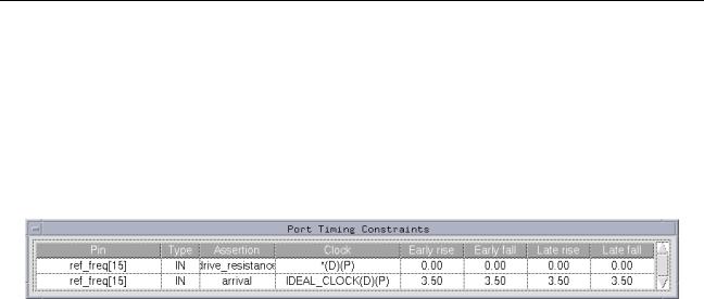
1.Click right mouse button on a port to display the pop-up menu (refer to Table 5-7 on page 117); move cursor to Show Constraints. Release the mouse button.
2.The port timing constraints are displayed (see Figure 5-8).
Figure 5-8 Sample Port Timing Constraints Listing
September 2000 |
133 |
Product Version 4.0 |

Ambit BuildGates Synthesis User Guide
Viewing the Schematic Design
Printing a Schematic
A schematic can be printed to a postscript file or to the default printer (specified in File– Printer Setup). You specify whether to print the full module schematic or just the current displayed view using View–Schematic Preferences–Printing–Scaling). The default scaling value is full page. In addition, page size, orientation, number of pages of a multi-page module, and color parameters can be specified; refer to Table 3-12, “Schematic
Preferences:Printing Options,” on page 55.
Set Print Scaling to Current View:
1.Select View–Schematic Preferences–Printing–Scaling–Current View.
2.Click Apply.S
3.Click Ok.
Print to a File:
1.Display the part of the netlist that you want to save to a file. Zoom in to the scale you prefer.
2.Click left mouse button on Save Schematic icon on the schematic tool bar. The Save a File dialog box is displayed.
3.Enter the path and file name to save the schematic.
4.Click Ok.
Print to the Default Printer:
1.Display the schematic module that you want to save to print.
2.Click left mouse button on Print Schematic icon on the schematic tool bar.
September 2000 |
134 |
Product Version 4.0 |