


Ambit BuildGates Synthesis User Guide
Viewing the Schematic Design
Highlighting Path Between Pins
The pin-to-pin panel, shown in Figure 5-2, is accessed from the several object pop-up menus.
There are three ways to select the From and To pins on the pin-to-pin panel.
■Type in the object name.
■Click left mouse button on the down arrow next to the pin input field and select an object from the history list of previously selected objects.
■Place the cursor in the From or To pin input field; the diamond-shaped check box to the left of the field is highlighted. Click left mouse button on the desired object on the schematic to list the object name in the input field.
Figure 5-2 Sample Pin-To-Pin Panel
|
XDraw |
Path Direction: To - From (default) |
Close Panel |
|
|
|
From - To |
|
|
|
Both Directions |
To Highlight the Path Between Two Pins:
1.Click left mouse button on the Options box to select the path direction.
2.Input the From and To pins as described above.
3.Click left mouse button on the XDraw icon to highlight the selected path on the schematic. The objects and path are highlighted based on either module level or path (default) depending on the setting in View–Schematic Preferences–Highlighting– Coloring Modes.
4.Click left mouse button on the Close icon to close the pin-to-pin panel.
September 2000 |
119 |
Product Version 4.0 |
Ambit BuildGates Synthesis User Guide
Viewing the Schematic Design
Viewing Bus Properties
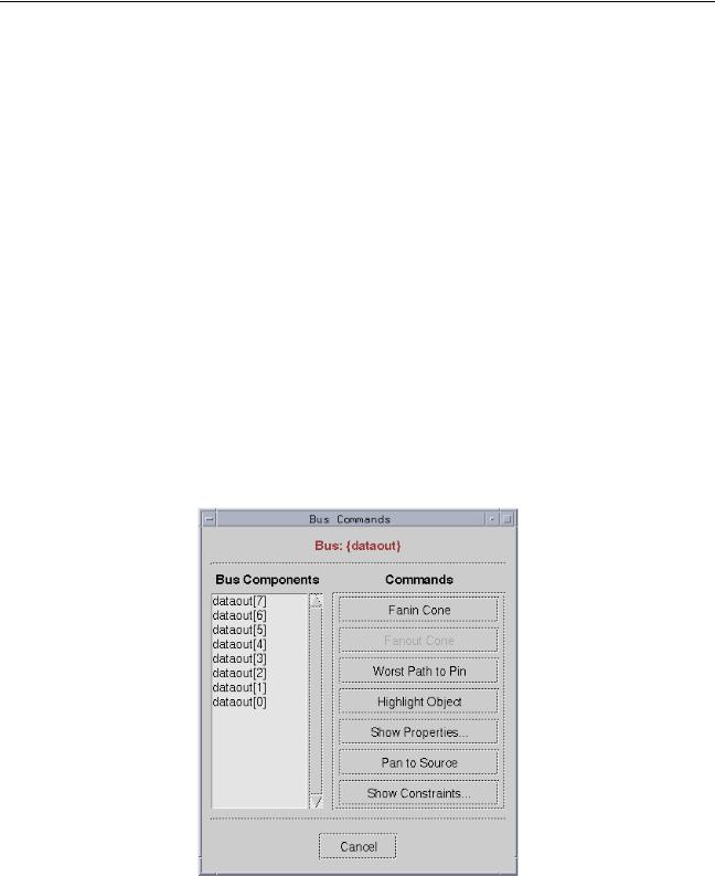
The bus command window, shown in Figure 5-3, is accessed from the bus and bus port popup menus described in Table 5-8. The right column contains commands that can be executed for the bus components listed in the left column.
Commands are grayed-out and not executable if the function is invalid for the selected bus component. For example, an output data bus can have a fanin cone but not a fanout cone; therefore, the fanout cone command will not be listed in the commands.
The Fanin Cone, Fanout Cone, Worst Path to Pin, Highlight Object, and Pan to Source commands simply highlight the specified parameter. Show Constraints displays a dialog box containing port timing constraint information (see Figure 5-8).
Show Properties displays a net properties dialog box containing instance, pin, and direction information; see Figure 5-4 for a sample. Doubling clicking the left mouse button on an instance name in the net properties dialog displays an instance properties dialog box with pin and net information for the selected instance. From there you can double click on a net name in the dialog and get another information box. You may continue double clicking on the objects listed in the displayed dialog boxes to access additional related object information.
Figure 5-3 Sample Bus Commands Dialog
Commands are grayed-out if the design function is invalid for the bus selection
September 2000 |
120 |
Product Version 4.0 |
Ambit BuildGates Synthesis User Guide
Viewing the Schematic Design
Figure 5-4 Sample Net Properties Dialog
Double click an instance to display another information list
The sample task below describes how to display the net and instance properties of the dataout[7] bus port; refer to Figure 5-3 and Figure 5-4 for clarification.
Display Net and Instance Properties of a Bus Port:
1.Click right mouse button on bus port on the schematic to display the pop-up menu (refer to Table 5-8); move cursor to Bus Commands. Release the mouse button.
2.A listing of the bus components and associated bus commands is displayed (see Figure 5-3).
3.Click left mouse button on the desired bus component to highlight it.
4.Click left mouse button on the Show Properties button to display the net properties (see
Figure 5-4).
5.Double click left mouse button on a listed instance to display additional properties.
6.To close all of the displayed dialog boxes, click left mouse button on Cancel.
September 2000 |
121 |
Product Version 4.0 |